
Technical Product Specification
Page 2
... implied, by estoppel or otherwise, to them. Revision History Revision -001 Revision History First release of documents which may make changes to only the standard Intel® Desktop Board D848PMB with BIOS identifier RC86510A.86A. Other names and brands may be published in the United States and other intellectual property rights.
... implied, by estoppel or otherwise, to them. Revision History Revision -001 Revision History First release of documents which may make changes to only the standard Intel® Desktop Board D848PMB with BIOS identifier RC86510A.86A. Other names and brands may be published in the United States and other intellectual property rights.
Technical Product Specification
Page 3
...'s notes are included to system integrators. Intended Audience The TPS is specifically not intended for the Intel® Desktop Board D848PMB. Preface This Technical Product Specification (TPS) specifies the board layout, components, connectors, power and environmental requirements, and the BIOS for general audiences. iii It describes the standard product and available manufacturing options.
...'s notes are included to system integrators. Intended Audience The TPS is specifically not intended for the Intel® Desktop Board D848PMB. Preface This Technical Product Specification (TPS) specifies the board layout, components, connectors, power and environmental requirements, and the BIOS for general audiences. iii It describes the standard product and available manufacturing options.
Technical Product Specification
Page 6
Intel Desktop Board D848PMB Technical Product Specification 2 Technical Reference 2.1 Introduction...43 2.2 Memory Map ...44 2.3 DMA Channels ...44 2.4 Fixed I/O Map...45 2.5 PCI Configuration Space Map 46 2.6 Interrupts ...47 2.7 ... 73 2.15.3 European Union Declaration of Conformity Statement 74 2.15.4 Product Ecology Statements 75 2.15.5 Product Certification Markings (Board Level 75 3 Overview of BIOS Features 3.1 Introduction...77 3.2 BIOS Flash Memory Organization 77 3.3 Resource Configuration 78 3.3.1 PCI Autoconfiguration 78 3.3.2 PCI IDE Support 78 3.4 System Management...
Intel Desktop Board D848PMB Technical Product Specification 2 Technical Reference 2.1 Introduction...43 2.2 Memory Map ...44 2.3 DMA Channels ...44 2.4 Fixed I/O Map...45 2.5 PCI Configuration Space Map 46 2.6 Interrupts ...47 2.7 ... 73 2.15.3 European Union Declaration of Conformity Statement 74 2.15.4 Product Ecology Statements 75 2.15.5 Product Certification Markings (Board Level 75 3 Overview of BIOS Features 3.1 Introduction...77 3.2 BIOS Flash Memory Organization 77 3.3 Resource Configuration 78 3.3.1 PCI Autoconfiguration 78 3.3.2 PCI IDE Support 78 3.4 System Management...

Technical Product Specification
Page 7
...Attached Devices 82 3.8.4 Changing the Default Boot Device During POST 82 3.9 Fast Booting Systems with Intel® Rapid BIOS Boot 83 3.9.1 Peripheral Selection and Configuration 83 3.9.2 Intel Rapid BIOS Boot 83 3.10 BIOS Security Features 84 4 BIOS Setup Program 4.1 Introduction...85 4.2 Maintenance Menu ...86 4.3 Main Menu...87 4.3.1 Additional System ... Devices Submenu 110 4.7.4 ATAPI CD-ROM Drives Submenu 111 4.8 Exit Menu ...111 5 Error Messages and Beep Codes 5.1 BIOS Error Messages 113 5.2 Port 80h POST Codes 115 5.3 Bus Initialization Checkpoints 119 5.4 Speaker ...120...
...Attached Devices 82 3.8.4 Changing the Default Boot Device During POST 82 3.9 Fast Booting Systems with Intel® Rapid BIOS Boot 83 3.9.1 Peripheral Selection and Configuration 83 3.9.2 Intel Rapid BIOS Boot 83 3.10 BIOS Security Features 84 4 BIOS Setup Program 4.1 Introduction...85 4.2 Maintenance Menu ...86 4.3 Main Menu...87 4.3.1 Additional System ... Devices Submenu 110 4.7.4 ATAPI CD-ROM Drives Submenu 111 4.8 Exit Menu ...111 5 Error Messages and Beep Codes 5.1 BIOS Error Messages 113 5.2 Port 80h POST Codes 115 5.3 Bus Initialization Checkpoints 119 5.4 Speaker ...120...
Technical Product Specification
Page 9
... 110 71. SCSI Hard Drive Activity LED Connector (Optional 59 30. Front Panel Connector 61 33. BIOS Setup Program Function Keys 86 48. SATA/PATA Submenus 97 57. BIOS Setup Configuration Jumper Settings 65 37. Safety Regulations ...73 42. Boot Device Menu Options 82 45. ...56 27. Auxiliary Front Panel Power/Sleep/Message-Waiting LED Connector 61 32. Desktop Board D848PMB Environmental Specifications 72 41. EMC Regulations...73 43. Supervisor and User Password Functions 84 46. BIOS Setup Program Menu Bar 85 47. Main Menu...87 50. PCI Configuration Submenu 90 ...
... 110 71. SCSI Hard Drive Activity LED Connector (Optional 59 30. Front Panel Connector 61 33. BIOS Setup Program Function Keys 86 48. SATA/PATA Submenus 97 57. BIOS Setup Configuration Jumper Settings 65 37. Safety Regulations ...73 42. Boot Device Menu Options 82 45. ...56 27. Auxiliary Front Panel Power/Sleep/Message-Waiting LED Connector 61 32. Desktop Board D848PMB Environmental Specifications 72 41. EMC Regulations...73 43. Supervisor and User Password Functions 84 46. BIOS Setup Program Menu Bar 85 47. Main Menu...87 50. PCI Configuration Submenu 90 ...
Technical Product Specification
Page 10
Exit Menu ...111 73. BIOS Error Messages 113 74. Runtime Code Uncompressed in F000 Shadow RAM 116 77. Lower Nibble High Byte Functions 120 80. Boot Block Recovery Code Checkpoints 115 76. Uncompressed INIT Code Checkpoints 115 75. Upper Nibble High Byte Functions 119 79. Bus Initialization Checkpoints 119 78. Intel Desktop Board D848PMB Technical Product Specification 72. Beep Codes...121 x
Exit Menu ...111 73. BIOS Error Messages 113 74. Runtime Code Uncompressed in F000 Shadow RAM 116 77. Lower Nibble High Byte Functions 120 80. Boot Block Recovery Code Checkpoints 115 76. Uncompressed INIT Code Checkpoints 115 75. Upper Nibble High Byte Functions 119 79. Bus Initialization Checkpoints 119 78. Intel Desktop Board D848PMB Technical Product Specification 72. Beep Codes...121 x
Technical Product Specification
Page 12
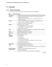
..., RS-232, front panel, PS/2 devices, and USB ports continued 12 Intel Desktop Board D848PMB Technical Product Specification 1.1 Overview 1.1.1 Feature Summary Table 1 summarizes the major features of : • Intel® 82848P Memory Controller Hub (MCH) • Intel® 82801EB I/O Controller Hub (ICH5) • 4 Mbit Firmware Hub ... Support Refer to Manufacturing Options on page 13 BIOS Instantly Available PC Technology • Intel/AMI BIOS (resident in an mPGA478 socket with a 400/533/800 MHz system bus • Support for an Intel® Celeron® processor in the 4 Mbit...
..., RS-232, front panel, PS/2 devices, and USB ports continued 12 Intel Desktop Board D848PMB Technical Product Specification 1.1 Overview 1.1.1 Feature Summary Table 1 summarizes the major features of : • Intel® 82848P Memory Controller Hub (MCH) • Intel® 82801EB I/O Controller Hub (ICH5) • 4 Mbit Firmware Hub ... Support Refer to Manufacturing Options on page 13 BIOS Instantly Available PC Technology • Intel/AMI BIOS (resident in an mPGA478 socket with a 400/533/800 MHz system bus • Support for an Intel® Celeron® processor in the 4 Mbit...
Technical Product Specification
Page 14
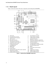
...fan connector R Chassis intrusion connector S 4 Mbit Firmware Hub (FWH) T Serial ATA connectors U BIOS Setup configuration jumper block V Auxiliary front panel power LED connector W Front panel connector X Front panel USB connector Y Intel 82801EB I/O Controller Hub (ICH5) Z Front panel USB connector AA Battery BB PCI bus add-...connectors CC Speaker DD Auxiliary line-in connector EE S/PDIF connector (optional FF ATAPI CD-ROM connector Figure 1. Intel Desktop Board D848PMB Technical Product Specification 1.1.3 Board Layout Figure 1 shows the location of the major components on the Desktop Board...
...fan connector R Chassis intrusion connector S 4 Mbit Firmware Hub (FWH) T Serial ATA connectors U BIOS Setup configuration jumper block V Auxiliary front panel power LED connector W Front panel connector X Front panel USB connector Y Intel 82801EB I/O Controller Hub (ICH5) Z Front panel USB connector AA Battery BB PCI bus add-...connectors CC Speaker DD Auxiliary line-in connector EE S/PDIF connector (optional FF ATAPI CD-ROM connector Figure 1. Intel Desktop Board D848PMB Technical Product Specification 1.1.3 Board Layout Figure 1 shows the location of the major components on the Desktop Board...
Technical Product Specification
Page 18
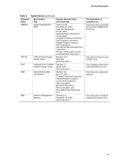
Intel Desktop Board D848PMB Technical Product Specification Table 3. Version 1.7, 1997, Institute of Electrical and Electronic Engineers. Version 1.0, January 25, 1995, Phoenix Technologies Limited and International Business Machines Corporation. Version 2.1, September 20, 1999, Intel Corporation. Version 2.0, May 2001, Intel Corporation. Revision 1.0, September 29, 1997, Intel...Play BIOS Specification Preboot Execution Environment SFX/SFX12V Power Supply Design Guide Version, Revision Date and Ownership Revision 1.0, March 12, 2002, Intel Corporation. Version 1.1, June 2002, Intel ...
Intel Desktop Board D848PMB Technical Product Specification Table 3. Version 1.7, 1997, Institute of Electrical and Electronic Engineers. Version 1.0, January 25, 1995, Phoenix Technologies Limited and International Business Machines Corporation. Version 2.1, September 20, 1999, Intel Corporation. Version 2.0, May 2001, Intel Corporation. Revision 1.0, September 29, 1997, Intel...Play BIOS Specification Preboot Execution Environment SFX/SFX12V Power Supply Design Guide Version, Revision Date and Ownership Revision 1.0, March 12, 2002, Intel Corporation. Version 1.1, June 2002, Intel ...
Technical Product Specification
Page 19
... USB Specification Title System Management BIOS TFX12V Power Supply Design Guide Universal Host Controller Interface Design Guide Universal Serial Bus Specification Version, Revision Date and Ownership Version 2.3.4, December 06, 2002, American Megatrends Incorporated, Award Software International Incorporated, Compaq Computer Corporation, Dell Computer Corporation, Hewlett-Packard Company, Intel Corporation, International Business Machines Corporation...
... USB Specification Title System Management BIOS TFX12V Power Supply Design Guide Universal Host Controller Interface Design Guide Universal Serial Bus Specification Version, Revision Date and Ownership Version 2.3.4, December 06, 2002, American Megatrends Incorporated, Award Software International Incorporated, Compaq Computer Corporation, Dell Computer Corporation, Hewlett-Packard Company, Intel Corporation, International Business Machines Corporation...
Technical Product Specification
Page 21
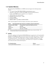
...MHz DDR266 800, 533, or 400 MHz Note: When using an 800 MHz system bus frequency processor, DDR333 memory is installed, the BIOS will attempt to optimize system throughput. ✏ NOTES To be fully compliant with all applicable DDR SDRAM memory specifications, the board should... for optimum performance. The processor's system bus frequency must be impacted or the DIMMs may be ... Product Description 1.6 System Memory The Desktop Board D848PMB has two DIMM sockets and supports the following memory features: • 2.6 V (only) 184-pin DDR SDRAM DIMMs with gold-plated contacts &#...
...MHz DDR266 800, 533, or 400 MHz Note: When using an 800 MHz system bus frequency processor, DDR333 memory is installed, the BIOS will attempt to optimize system throughput. ✏ NOTES To be fully compliant with all applicable DDR SDRAM memory specifications, the board should... for optimum performance. The processor's system bus frequency must be impacted or the DIMMs may be ... Product Description 1.6 System Memory The Desktop Board D848PMB has two DIMM sockets and supports the following memory features: • 2.6 V (only) 184-pin DDR SDRAM DIMMs with gold-plated contacts &#...
Technical Product Specification
Page 23
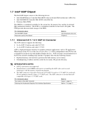
...legacy 3.3 V AGP cards. While based on the bus for graphics-intensive applications, such as 3D applications. The ICH5 is independent of the BIOS. The FWH provides the nonvolatile storage of the PCI bus and is a high-performance interface for nearly 100 percent efficiency # INTEGRATOR'S NOTES ...(FWH) The GMCH is keyed for the system bus, the memory bus, and the Accelerated Hub Architecture interface. For information about The Intel 848P chipset Resources used by the chipset Refer to avoid interference with the memory retention mechanism. • The AGP connector is a centralized...
...legacy 3.3 V AGP cards. While based on the bus for graphics-intensive applications, such as 3D applications. The ICH5 is independent of the BIOS. The FWH provides the nonvolatile storage of the PCI bus and is a high-performance interface for nearly 100 percent efficiency # INTEGRATOR'S NOTES ...(FWH) The GMCH is keyed for the system bus, the memory bus, and the Accelerated Hub Architecture interface. For information about The Intel 848P chipset Resources used by the chipset Refer to avoid interference with the memory retention mechanism. • The AGP connector is a centralized...
Technical Product Specification
Page 25
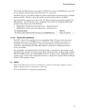
..., unlike Parallel ATA IDE which supports a master/slave configuration and two devices per port. One device can be installed on the D848PMB board Refer to Figure 13, page 58 1.7.3.2 Serial ATA Interfaces The ICH5's Serial ATA controller offers two independent Serial ATA ports ... underlying Serial ATA functionality is used . In legacy mode, standard IDE I/O and IRQ resources are assigned (IRQ 14 and 15). The BIOS supports Logical Block Addressing (LBA) and Extended Cylinder Head Sector (ECHS) translation modes. Product Description The Parallel ATA IDE interfaces also support ATAPI...
..., unlike Parallel ATA IDE which supports a master/slave configuration and two devices per port. One device can be installed on the D848PMB board Refer to Figure 13, page 58 1.7.3.2 Serial ATA Interfaces The ICH5's Serial ATA controller offers two independent Serial ATA ports ... underlying Serial ATA functionality is used . In legacy mode, standard IDE I/O and IRQ resources are assigned (IRQ 14 and 15). The BIOS supports Logical Block Addressing (LBA) and Extended Cylinder Head Sector (ECHS) translation modes. Product Description The Parallel ATA IDE interfaces also support ATAPI...
Technical Product Specification
Page 26
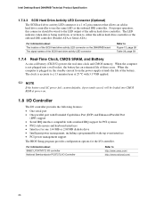
... as the onboard IDE controller. When the computer is a 1 x 2-pin connector that allows an add-in hard drive controller. Intel Desktop Board D848PMB Technical Product Specification 1.7.3.3 SCSI Hard Drive Activity LED Connector (Optional) The SCSI hard drive activity LED connector is not plugged into CMOS... MB diskette drive • Intelligent power management, including a programmable wake-up event interface • PCI power management support The BIOS Setup program provides configuration options for the I /O Controller Refer to http://www.smsc.com/ http://www.national.com/ 26
... as the onboard IDE controller. When the computer is a 1 x 2-pin connector that allows an add-in hard drive controller. Intel Desktop Board D848PMB Technical Product Specification 1.7.3.3 SCSI Hard Drive Activity LED Connector (Optional) The SCSI hard drive activity LED connector is not plugged into CMOS... MB diskette drive • Intelligent power management, including a programmable wake-up event interface • PCI power management support The BIOS Setup program provides configuration options for the I /O Controller Refer to http://www.smsc.com/ http://www.national.com/ 26
Technical Product Specification
Page 27
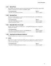
... program to 115.2 kbits/sec with BIOS support. Power to Figure 10, page 51 1.8.2 Parallel Port The 25-pin D-Sub parallel port connector is connected or disconnected. For information about The location ... in the top PS/2 connector. For information about The location of the diskette drive connector on the D848PMB board The supported diskette drive capacities and sizes Refer to set the parallel port mode. Use the BIOS Setup program to Figure 13, page 58 Table 57, page 98 1.8.4 Keyboard and Mouse Interface PS...
... program to 115.2 kbits/sec with BIOS support. Power to Figure 10, page 51 1.8.2 Parallel Port The 25-pin D-Sub parallel port connector is connected or disconnected. For information about The location ... in the top PS/2 connector. For information about The location of the diskette drive connector on the D848PMB board The supported diskette drive capacities and sizes Refer to set the parallel port mode. Use the BIOS Setup program to Figure 13, page 58 Table 57, page 98 1.8.4 Keyboard and Mouse Interface PS...
Technical Product Specification
Page 37
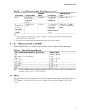
... peripherals powered by battery or external source. Total system power is required. No power to the system. Service can wake up devices used in the BIOS Setup program. Notes: 1. Dependent on the system configuration, including add-in the S5 state. ✏ NOTE The use of wake-up the computer... Table 10...
... peripherals powered by battery or external source. Total system power is required. No power to the system. Service can wake up devices used in the BIOS Setup program. Notes: 1. Dependent on the system configuration, including add-in the S5 state. ✏ NOTE The use of wake-up the computer... Table 10...
Technical Product Specification
Page 38
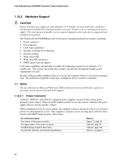
... of standby current required depends on the wake devices supported and manufacturing options. The total amount of the power connector The BIOS Setup program's Boot menu The ATX12V, SFX12V, and TFX12V specifications Refer to access the computer when it was in before ...the power supply removes all non-standby voltages. The sections discussing these features describe the incremental standby power requirements for each. Intel Desktop Board D848PMB Technical Product Specification 1.12.2 Hardware Support CAUTION Ensure that the power supply provides adequate +5 V standby current if LAN wake...
... of standby current required depends on the wake devices supported and manufacturing options. The total amount of the power connector The BIOS Setup program's Boot menu The ATX12V, SFX12V, and TFX12V specifications Refer to access the computer when it was in before ...the power supply removes all non-standby voltages. The sections discussing these features describe the incremental standby power requirements for each. Intel Desktop Board D848PMB Technical Product Specification 1.12.2 Hardware Support CAUTION Ensure that the power supply provides adequate +5 V standby current if LAN wake...
Technical Product Specification
Page 42
Intel Desktop Board D848PMB Technical Product Specification 1.12.2.6 Resume on Ring The operation of Resume on Ring can be summarized as follows: • Resumes operation from ACPI S1 or ...# signal on the PCI bus is asserted, the computer wakes from an ACPI S1, S3, S4, or S5 state (with Wake on PME enabled in BIOS). 42
Intel Desktop Board D848PMB Technical Product Specification 1.12.2.6 Resume on Ring The operation of Resume on Ring can be summarized as follows: • Resumes operation from ACPI S1 or ...# signal on the PCI bus is asserted, the computer wakes from an ACPI S1, S3, S4, or S5 state (with Wake on PME enabled in BIOS). 42
Technical Product Specification
Page 44
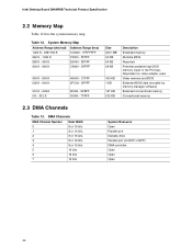
... 1 KB 127 KB 512 KB Description Extended memory Runtime BIOS Reserved Potential available high DOS memory (open to the PCI bus). Video memory and BIOS Extended BIOS data (movable by memory manager software) Extended conventional memory Conventional memory 2.3 DMA Channels Table 13. Intel Desktop Board D848PMB Technical Product Specification 2.2 Memory Map Table 12 lists the...
... 1 KB 127 KB 512 KB Description Extended memory Runtime BIOS Reserved Potential available high DOS memory (open to the PCI bus). Video memory and BIOS Extended BIOS data (movable by memory manager software) Extended conventional memory Conventional memory 2.3 DMA Channels Table 13. Intel Desktop Board D848PMB Technical Product Specification 2.2 Memory Map Table 12 lists the...

Technical Product Specification
Page 64
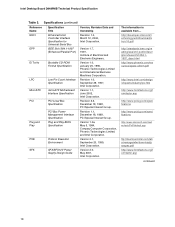
Intel Desktop Board D848PMB Technical Product Specification 2.9 Jumper Blocks CAUTION Do not move any jumpers with the power on. A 12 9 10 J8A1 B 1 3 J8H3 Item A B Description Front panel audio connector/jumper block BIOS Setup configuration jumper block OM16427 Reference Designator J8A1 J8H3 Figure 17. Location of the jumper blocks. Always turn off the power and...
Intel Desktop Board D848PMB Technical Product Specification 2.9 Jumper Blocks CAUTION Do not move any jumpers with the power on. A 12 9 10 J8A1 B 1 3 J8H3 Item A B Description Front panel audio connector/jumper block BIOS Setup configuration jumper block OM16427 Reference Designator J8A1 J8H3 Figure 17. Location of the jumper blocks. Always turn off the power and...


