
Product Specification
Page 6
Intel Desktop Board D845BG/D845PT Technical Product Specification 2 Technical Reference 2.1 Introduction...47 2.2 Memory Map ...47 2.3 I/O Map ...48 2.4 DMA Channels ...50 2.5 PCI Configuration Space Map 50 2.6 Interrupts ...51 2.7 PCI Interrupt Routing Map 52 2.8 Connectors ...54 2.8.1 Back Panel Connectors 55 2.8.2 Internal I/O Connectors 58 2.8.3 External I/O Connectors 71 2.9 Jumper Blocks...75 2.9.1 Front Panel Audio Connector/Jumper Block 75 2.9.2 BIOS Setup Configuration Jumper Block 76...
Intel Desktop Board D845BG/D845PT Technical Product Specification 2 Technical Reference 2.1 Introduction...47 2.2 Memory Map ...47 2.3 I/O Map ...48 2.4 DMA Channels ...50 2.5 PCI Configuration Space Map 50 2.6 Interrupts ...51 2.7 PCI Interrupt Routing Map 52 2.8 Connectors ...54 2.8.1 Back Panel Connectors 55 2.8.2 Internal I/O Connectors 58 2.8.3 External I/O Connectors 71 2.9 Jumper Blocks...75 2.9.1 Front Panel Audio Connector/Jumper Block 75 2.9.2 BIOS Setup Configuration Jumper Block 76...
Product Specification
Page 8
... and Events 41 11. Fan Connector Function/Operation 43 12. Specifications ...19 5. PCI Configuration Space Map 50 16. PS/2 Mouse/Keyboard Connector 56 19. Auxiliary Line In Connector 60 27. D845PT Board Dimensions 78 20. Supported ...D845PT Add-in Board and Peripheral Interface Connectors 64 15. Localized High Temperature Zones 86 Tables 1. PCI Interrupt Routing Map 53 18. D845BG Add-in Board and Peripheral Interface Connectors 65 16. Back Panel Connectors 55 12. Intel Desktop Board D845BG/D845PT Technical Product Specification 10. LAN Connector...
... and Events 41 11. Fan Connector Function/Operation 43 12. Specifications ...19 5. PCI Configuration Space Map 50 16. PS/2 Mouse/Keyboard Connector 56 19. Auxiliary Line In Connector 60 27. D845PT Board Dimensions 78 20. Supported ...D845PT Add-in Board and Peripheral Interface Connectors 64 15. Localized High Temperature Zones 86 Tables 1. PCI Interrupt Routing Map 53 18. D845BG Add-in Board and Peripheral Interface Connectors 65 16. Back Panel Connectors 55 12. Intel Desktop Board D845BG/D845PT Technical Product Specification 10. LAN Connector...
Product Specification
Page 9
.... Video Configuration Submenu 113 71. PCI IDE Connectors 70 39. Serial Port B Connector 72 42. D845BG/D845PT Board Environmental Specifications 87 54. EMC Regulations...88 56. BIOS Setup Program Menu Bar 99 58. Hard Disk Drives Submenu 119 77. Removable Devices Submenu 119 78. Front Panel Audio Connector/Jumper Block 76 48. Boot Configuration Submenu...
.... Video Configuration Submenu 113 71. PCI IDE Connectors 70 39. Serial Port B Connector 72 42. D845BG/D845PT Board Environmental Specifications 87 54. EMC Regulations...88 56. BIOS Setup Program Menu Bar 99 58. Hard Disk Drives Submenu 119 77. Removable Devices Submenu 119 78. Front Panel Audio Connector/Jumper Block 76 48. Boot Configuration Submenu...
Product Specification
Page 14
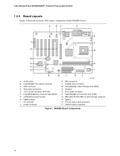
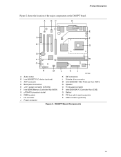
... Board D845BG/D845PT Technical Product Specification 1.2.3 Board Layouts Figure 1 shows the location of the major components on the D845BG board. A BC D E T F S G R Q H P O I N M L K J OM12997 A Audio codec B Intel 82562ET PLC device (optional) C AGP connector D Back panel connectors E +12 V power connector (ATX12V) F Intel 82845 Memory Controller Hub (MCH) G µPGA478 processor socket H DIMM sockets I I/O controller J Power connector K IDE connectors L Diskette drive connector M Intel 82802AB 4 Mbit...
... Board D845BG/D845PT Technical Product Specification 1.2.3 Board Layouts Figure 1 shows the location of the major components on the D845BG board. A BC D E T F S G R Q H P O I N M L K J OM12997 A Audio codec B Intel 82562ET PLC device (optional) C AGP connector D Back panel connectors E +12 V power connector (ATX12V) F Intel 82845 Memory Controller Hub (MCH) G µPGA478 processor socket H DIMM sockets I I/O controller J Power connector K IDE connectors L Diskette drive connector M Intel 82802AB 4 Mbit...
Product Specification
Page 15
... connector (ATX12V) F Intel 82845 Memory Controller Hub (MCH) G µPGA478 processor socket H DIMM sockets I I/O controller J Power connector K IDE connectors L Diskette drive connector M Intel 82802AB 4 Mbit Firmware Hub (FWH) N Speaker O Front panel connector P Intel 82801BA I/O Controller Hub (ICH2) Q Battery R PCI bus add-in card connectors S CNR connector (optional) Figure 2. Product Description Figure 2 shows the location of the major components on the D845PT board. D845PT...
... connector (ATX12V) F Intel 82845 Memory Controller Hub (MCH) G µPGA478 processor socket H DIMM sockets I I/O controller J Power connector K IDE connectors L Diskette drive connector M Intel 82802AB 4 Mbit Firmware Hub (FWH) N Speaker O Front panel connector P Intel 82801BA I/O Controller Hub (ICH2) Q Battery R PCI bus add-in card connectors S CNR connector (optional) Figure 2. Product Description Figure 2 shows the location of the major components on the D845PT board. D845PT...
Product Specification
Page 27
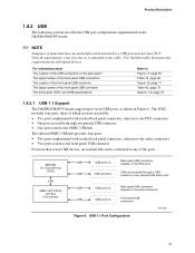
... panel USB connectors adjacent to the PS/2 ports USB port accesible through a USB connector on an optional CNR add-in Figure 6. Product Description 1.8.2 USB The following sections describe the USB port configurations implemented on the D845BG/D845PT boards. ✏ NOTE Computer systems that meets the requirements ...connected to any of the front panel USB connector The front panel, UHCI, and USB specifications Refer to Figure 11, page 55 Table 19, page 56 Figure 16, page 71 Table 42, page 72 Section 1.5, page 19 1.8.2.1 USB 1.1 Support The D845BG/D845PT boards support up to the cable....
... panel USB connectors adjacent to the PS/2 ports USB port accesible through a USB connector on an optional CNR add-in Figure 6. Product Description 1.8.2 USB The following sections describe the USB port configurations implemented on the D845BG/D845PT boards. ✏ NOTE Computer systems that meets the requirements ...connected to any of the front panel USB connector The front panel, UHCI, and USB specifications Refer to Figure 11, page 55 Table 19, page 56 Figure 16, page 71 Table 42, page 72 Section 1.5, page 19 1.8.2.1 USB 1.1 Support The D845BG/D845PT boards support up to the cable....
Product Specification
Page 28
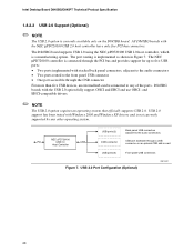
...more than five USB devices, an external hub can be connected to the front panel USB connector • One port accessible through a USB connector on the D845BG board. Intel Desktop Board D845BG/D845PT Technical Product Specification 1.8.2.2 USB 2.0 Support (Optional) ✏ NOTE The USB ... tested with the NEC µPD720100 USB 2.0 host controller have only five PCI bus connectors. USB 2.0 Port Configuration (Optional) OM12337 28 D845BG boards with stacked back panel connectors, adjacent to the audio connectors • Two ports routed to any other operating system.
...more than five USB devices, an external hub can be connected to the front panel USB connector • One port accessible through a USB connector on the D845BG board. Intel Desktop Board D845BG/D845PT Technical Product Specification 1.8.2.2 USB 2.0 Support (Optional) ✏ NOTE The USB ... tested with the NEC µPD720100 USB 2.0 host controller have only five PCI bus connectors. USB 2.0 Port Configuration (Optional) OM12337 28 D845BG boards with stacked back panel connectors, adjacent to the audio connectors • Two ports routed to any other operating system.
Product Specification
Page 55
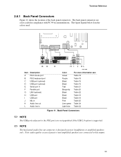
... port I USB port J Mic in K Audio line out L Audio line in compliance with PC 99 recommendations. The figure legend below lists the colors used. Back Panel Connectors ✏ NOTE The USB ports adjacent to this output. 55 Poor audio quality occurs if passive (non-amplified) speakers are connected to the PS/2 ports... Table 19 Table 19 Table 21 Table 20 Table 22 Table 19 Table 19 Table 25 Table 24 Table 23 Figure 11. Technical Reference 2.8.1 Back Panel Connectors Figure 11 shows the location of the back...
... port I USB port J Mic in K Audio line out L Audio line in compliance with PC 99 recommendations. The figure legend below lists the colors used. Back Panel Connectors ✏ NOTE The USB ports adjacent to this output. 55 Poor audio quality occurs if passive (non-amplified) speakers are connected to the PS/2 ports... Table 19 Table 19 Table 21 Table 20 Table 22 Table 19 Table 19 Table 25 Table 24 Table 23 Figure 11. Technical Reference 2.8.1 Back Panel Connectors Figure 11 shows the location of the back...
Product Specification
Page 72
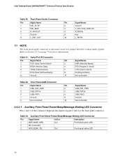
... on page 75 for routing audio signals. Table 41. Front Panel USB Connector Pin Signal Name Pin Signal Name 1 USB_FNT_PWR 2 USB_FNT_PWR 3 USB_FNT1# 4 USB_FNT2# 5 USB_FNT1 6 USB_FNT2 7 Ground 8 Ground 9 Not connected 10 Not connected 2.8.3.1 Auxiliary Front Panel Power/Sleep/Message-Waiting LED Connector Pins 1 and 3 of the front panel connector. Intel Desktop Board D845BG/D845PT Technical Product Specification Table 40.
... on page 75 for routing audio signals. Table 41. Front Panel USB Connector Pin Signal Name Pin Signal Name 1 USB_FNT_PWR 2 USB_FNT_PWR 3 USB_FNT1# 4 USB_FNT2# 5 USB_FNT1 6 USB_FNT2 7 Ground 8 Ground 9 Not connected 10 Not connected 2.8.3.1 Auxiliary Front Panel Power/Sleep/Message-Waiting LED Connector Pins 1 and 3 of the front panel connector. Intel Desktop Board D845BG/D845PT Technical Product Specification Table 40.
Product Specification
Page 73
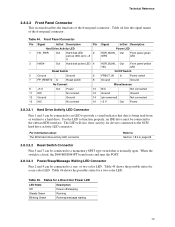
...to an LED to provide a visual indicator that is closed, the D845BG/D845PT board resets and runs the POST. 2.8.3.2.3 Power/Sleep/Message Waiting LED Connector Pins 2 and 4 can be connected to the SCSI hard drive activity LED connector. The LED will also show activity for a two-color LED. When... the switch is normally open. Table 46 shows the possible states for devices connected to the onboard IDE interface. Table 44. Front Panel Connector Pin Signal In/Out Description Pin Hard Drive Activity LED 1 HD_PWR Out Hard disk LED 2 pull-up (330 Ω) to +5 V 3 HAD...
...to an LED to provide a visual indicator that is closed, the D845BG/D845PT board resets and runs the POST. 2.8.3.2.3 Power/Sleep/Message Waiting LED Connector Pins 2 and 4 can be connected to the SCSI hard drive activity LED connector. The LED will also show activity for a two-color LED. When... the switch is normally open. Table 46 shows the possible states for devices connected to the onboard IDE interface. Table 44. Front Panel Connector Pin Signal In/Out Description Pin Hard Drive Activity LED 1 HD_PWR Out Hard disk LED 2 pull-up (330 Ω) to +5 V 3 HAD...

Intel Desktop Board D845PT/D845BG Product Guide
Page 5
... 66 Exit Menu ...66 5 Technical Reference Board Connectors ...67 Back Panel Connectors 68 Midboard Connectors 69 Audio Connectors 69 Power and Hardware Connectors 70 Add-In Card and Peripheral Interface Connectors 71 Front Panel Connectors 73 Desktop Board Resources 74 Memory Map ...74 DMA Channels ...74 I /O Shield 24 5. D845PT Board Components 11 2. D845PT Board Mounting Holes 25 6. D845BG Board Mounting Holes...
... 66 Exit Menu ...66 5 Technical Reference Board Connectors ...67 Back Panel Connectors 68 Midboard Connectors 69 Audio Connectors 69 Power and Hardware Connectors 70 Add-In Card and Peripheral Interface Connectors 71 Front Panel Connectors 73 Desktop Board Resources 74 Memory Map ...74 DMA Channels ...74 I /O Shield 24 5. D845PT Board Components 11 2. D845PT Board Mounting Holes 25 6. D845BG Board Mounting Holes...

Intel Desktop Board D845PT/D845BG Product Guide
Page 6
...23. Back Panel Connectors 68 21. Primary/Secondary IDE Master/Slave Submenus 57 17. Video Configuration Submenu 60 20. Removable Devices Submenu 65 27. Maintenance Menu ...48 9. Hard Disk Drives Submenu 65 26. Front Panel Audio Connector Signal Names 69 vi Intel Desktop Boards D845PT and D845BG... Product Guide 11. AGP Card with Retention Notch 33 14. Connecting the IDE Cable 37 18. Audio Connectors ...69 22. Processors Supported by the Desktop ...
...23. Back Panel Connectors 68 21. Primary/Secondary IDE Master/Slave Submenus 57 17. Video Configuration Submenu 60 20. Removable Devices Submenu 65 27. Maintenance Menu ...48 9. Hard Disk Drives Submenu 65 26. Front Panel Audio Connector Signal Names 69 vi Intel Desktop Boards D845PT and D845BG... Product Guide 11. AGP Card with Retention Notch 33 14. Connecting the IDE Cable 37 18. Audio Connectors ...69 22. Processors Supported by the Desktop ...

Intel Desktop Board D845PT/D845BG Product Guide
Page 11
... on the D845PT board. D845PT Board Components 11 AD1885 audio codec P Diskette drive connector B AGP connector Q Firmware Hub (FWH) C CD-ROM connector (ATAPI) R Intel 82801BA I/O Controller Hub (ICH2) D Auxiliary line-in connector (ATAPI) S BIOS configuration jumper block E Back panel connectors T SCSI hard drive activity LED connector F 12 V processor core voltage connector U Speaker G Rear chassis fan connector (tachometer input) V Chassis intrusion connector H Intel 82845 Memory...
... on the D845PT board. D845PT Board Components 11 AD1885 audio codec P Diskette drive connector B AGP connector Q Firmware Hub (FWH) C CD-ROM connector (ATAPI) R Intel 82801BA I/O Controller Hub (ICH2) D Auxiliary line-in connector (ATAPI) S BIOS configuration jumper block E Back panel connectors T SCSI hard drive activity LED connector F 12 V processor core voltage connector U Speaker G Rear chassis fan connector (tachometer input) V Chassis intrusion connector H Intel 82845 Memory...

Intel Desktop Board D845PT/D845BG Product Guide
Page 12
Intel Desktop Boards D845PT and D845BG Product Guide Figure 2 shows the location of the major components on the D845BG board. A BCD E DD F G CC H BB I Processor socket X Front panel connector J Processor fan connector (tachometer input) Y Alternate power/sleep LED connector K DIMM sockets Z Front panel USB connector L Serial port B connector AA Battery M Power connector BB PCI bus add-in card connectors N Secondary IDE connector CC...
Intel Desktop Boards D845PT and D845BG Product Guide Figure 2 shows the location of the major components on the D845BG board. A BCD E DD F G CC H BB I Processor socket X Front panel connector J Processor fan connector (tachometer input) Y Alternate power/sleep LED connector K DIMM sockets Z Front panel USB connector L Serial port B connector AA Battery M Power connector BB PCI bus add-in card connectors N Secondary IDE connector CC...

Intel Desktop Board D845PT/D845BG Product Guide
Page 16
...connectors (PCI bus connector 6 slot shared with CNR) • One AGP connector • One optional CNR connector (slot shared with PCI bus connector 6) 16 four ports routed to the back panel, two to the front panel connector, and one to seven USB 1.1 ports via the ICH2 and I/O controller; Intel Desktop Boards D845PT...Use a shielded cable that have the following add-in card connectors: The D845PT board has: • Three PCI bus add-in card connectors (PCI bus connector 3 slot shared with CNR) • One AGP connector • One optional CNR connector (slot shared with UHCI.
...connectors (PCI bus connector 6 slot shared with CNR) • One AGP connector • One optional CNR connector (slot shared with PCI bus connector 6) 16 four ports routed to the back panel, two to the front panel connector, and one to seven USB 1.1 ports via the ICH2 and I/O controller; Intel Desktop Boards D845PT...Use a shielded cable that have the following add-in card connectors: The D845PT board has: • Three PCI bus add-in card connectors (PCI bus connector 3 slot shared with CNR) • One AGP connector • One optional CNR connector (slot shared with UHCI.
Intel Desktop Board D845PT/D845BG Product Guide
Page 67
... example) to devices inside the computer chassis, such as fans and internal peripherals. 5 Technical Reference Board Connectors The board connectors can be divided into three groups: • Back panel connectors • Midboard connectors Audio connectors Power and hardware connectors Add-in the load presented by the external devices could cause damage to the computer...
... example) to devices inside the computer chassis, such as fans and internal peripherals. 5 Technical Reference Board Connectors The board connectors can be divided into three groups: • Back panel connectors • Midboard connectors Audio connectors Power and hardware connectors Add-in the load presented by the external devices could cause damage to the computer...

Intel Desktop Board D845PT/D845BG Product Guide
Page 68
Back Panel Connectors ✏ NOTE The line out connector, located on the board. Intel Desktop Boards D845PT and D845BG Product Guide Back Panel Connectors Figure 20 shows the back panel connectors on the back panel, is designed to this output. 68 A E G C BD F H I J KL Item A B C D E F G H I J K L Description PS/2 mouse port PS/2 keyboard port USB port 0 USB port 1 Parallel port Serial port A RJ-...
Back Panel Connectors ✏ NOTE The line out connector, located on the board. Intel Desktop Boards D845PT and D845BG Product Guide Back Panel Connectors Figure 20 shows the back panel connectors on the back panel, is designed to this output. 68 A E G C BD F H I J KL Item A B C D E F G H I J K L Description PS/2 mouse port PS/2 keyboard port USB port 0 USB port 1 Parallel port Serial port A RJ-...
Intel Desktop Board D845PT/D845BG Product Guide
Page 73
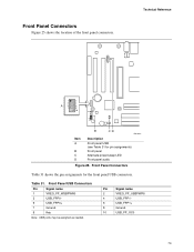
... Note: USB ports may be assigned as needed. Table 31. Front Panel Connectors Figure 25 shows the location of the front panel connectors. 12 9 10 Technical Reference 1 2 3 4 A 5 6 7 8 10 16 15 2 1 Item A B C D B CD OM12641 Description Front panel USB (see Table 31 for the front panel USB connectors. Front Panel Connectors Table 31 shows the pin assignments for pin assignments) Front...
... Note: USB ports may be assigned as needed. Table 31. Front Panel Connectors Figure 25 shows the location of the front panel connectors. 12 9 10 Technical Reference 1 2 3 4 A 5 6 7 8 10 16 15 2 1 Item A B C D B CD OM12641 Description Front panel USB (see Table 31 for the front panel USB connectors. Front Panel Connectors Table 31 shows the pin assignments for pin assignments) Front...
Quick Reference Guide
Page 5
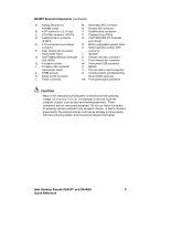
... computer chassis. Intel Desktop Boards D845PT and D845BG 5 Quick Reference Secondary IDE connector AD1885 codec N. BIOS configuration jumper block connector S. Processor socket W. Processor fan connector X. DIMM sockets Z. M. Intel® 82801BA I . A fault in card connectors J. D845PT Board Components (continued) A. Primary IDE connector B. AGP connector (1.5 V only) O. Auxiliary line-in connector P. SCSI hard drive activity LED F. Speaker G. Front chassis fan connector H. Front panel USB connector I /O Controller (ATAPI...
... computer chassis. Intel Desktop Boards D845PT and D845BG 5 Quick Reference Secondary IDE connector AD1885 codec N. BIOS configuration jumper block connector S. Processor socket W. Processor fan connector X. DIMM sockets Z. M. Intel® 82801BA I . A fault in card connectors J. D845PT Board Components (continued) A. Primary IDE connector B. AGP connector (1.5 V only) O. Auxiliary line-in connector P. SCSI hard drive activity LED F. Speaker G. Front chassis fan connector H. Front panel USB connector I /O Controller (ATAPI...
Quick Reference Guide
Page 7
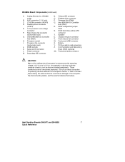
...) Q. Speaker U. Intel Desktop Boards D845PT and D845BG 7 Quick Reference Rear chassis fan connector (tachometer input) G. BIOS configuration jumper block S. Battery Y. Communication and Networking Riser (CNR) (optional) AA. CD-ROM connector (ATAPI) D. Serial port B connector L. Intel 82845 Memory Controller Hub (MCH) H. SCSI hard drive activity LED connector T. Power connector M. Diskette drive connector P. Chassis intrusion connector V. Front panel USB connector X. Front panel audio connector CAUTION Many...
...) Q. Speaker U. Intel Desktop Boards D845PT and D845BG 7 Quick Reference Rear chassis fan connector (tachometer input) G. BIOS configuration jumper block S. Battery Y. Communication and Networking Riser (CNR) (optional) AA. CD-ROM connector (ATAPI) D. Serial port B connector L. Intel 82845 Memory Controller Hub (MCH) H. SCSI hard drive activity LED connector T. Power connector M. Diskette drive connector P. Chassis intrusion connector V. Front panel USB connector X. Front panel audio connector CAUTION Many...


