
Product Specification
Page 6
Intel Desktop Board D845BG/D845PT Technical Product Specification 2 Technical Reference 2.1 Introduction...47 2.2 Memory Map ...47 2.3 I/O Map ...48 2.4 DMA Channels ...50 2.5 PCI Configuration Space Map 50 2.6 Interrupts ...51 2.7 PCI Interrupt Routing Map 52 2.8 Connectors ...54 2.8.1 Back Panel Connectors 55 2.8.2 Internal I/O Connectors 58 2.8.3 External I/O Connectors 71 2.9 Jumper Blocks...75 2.9.1 Front Panel Audio Connector/Jumper Block 75 2.9.2 BIOS...
Intel Desktop Board D845BG/D845PT Technical Product Specification 2 Technical Reference 2.1 Introduction...47 2.2 Memory Map ...47 2.3 I/O Map ...48 2.4 DMA Channels ...50 2.5 PCI Configuration Space Map 50 2.6 Interrupts ...51 2.7 PCI Interrupt Routing Map 52 2.8 Connectors ...54 2.8.1 Back Panel Connectors 55 2.8.2 Internal I/O Connectors 58 2.8.3 External I/O Connectors 71 2.9 Jumper Blocks...75 2.9.1 Front Panel Audio Connector/Jumper Block 75 2.9.2 BIOS...
Product Specification
Page 8
.../O Connectors 71 17. PCI Interrupt Routing Map 53 18. Serial Port A Connector 57 22. Audio Line Out Connector 57 25. D845PT Board Dimensions 78 20. Supported Memory Configurations 24 7. System Memory Map 47 13. LAN Connector (Optional 57 23. Mic In Connector ...57 26.... Intel Desktop Board D845BG/D845PT Technical Product Specification 10. ATAPI CD-ROM Connector 60 28. Back Panel Connectors 55 12. Wake-up Devices and Events 41 11. Interrupts ...51 17. Location of Pressing...
.../O Connectors 71 17. PCI Interrupt Routing Map 53 18. Serial Port A Connector 57 22. Audio Line Out Connector 57 25. D845PT Board Dimensions 78 20. Supported Memory Configurations 24 7. System Memory Map 47 13. LAN Connector (Optional 57 23. Mic In Connector ...57 26.... Intel Desktop Board D845BG/D845PT Technical Product Specification 10. ATAPI CD-ROM Connector 60 28. Back Panel Connectors 55 12. Wake-up Devices and Events 41 11. Interrupts ...51 17. Location of Pressing...
Product Specification
Page 9
... Menu 100 60. PCI Configuration Submenu 104 64. Diskette Drive Connector 69 38. Serial Port B Connector 72 42. Front Panel Audio Connector/Jumper Block 76 48. Fan Connector Current Capability 84 52. Power Menu ...115 73. Event Log Configuration Submenu 112... 70. Exit Menu ...120 ix AGP Connector ...68 37. BIOS Setup Configuration Jumper Settings 76 49. D845BG/D845PT Board Environmental Specifications 87 54. Boot Device Priority Submenu 118 76. Chassis Intrusion Connector 63 34. Safety Regulations ...88 55. ...
... Menu 100 60. PCI Configuration Submenu 104 64. Diskette Drive Connector 69 38. Serial Port B Connector 72 42. Front Panel Audio Connector/Jumper Block 76 48. Fan Connector Current Capability 84 52. Power Menu ...115 73. Event Log Configuration Submenu 112... 70. Exit Menu ...120 ix AGP Connector ...68 37. BIOS Setup Configuration Jumper Settings 76 49. D845BG/D845PT Board Environmental Specifications 87 54. Boot Device Priority Submenu 118 76. Chassis Intrusion Connector 63 34. Safety Regulations ...88 55. ...
Product Specification
Page 13
... ACPI, Plug and Play, and SMBIOS. Table 3. For information about Available configurations for the D845BG and D845PT boards Refer to RAM support • Wake on PCI, CNR, RS-232, front panel, PS/2 devices, and USB ports For information about The board's compliance level with PCI bus connector 3... on the D845PT board) Intel® 82562ET 10/100 Mbit/sec Platform LAN Connect (PLC) device Support for PCI Local Bus...
... ACPI, Plug and Play, and SMBIOS. Table 3. For information about Available configurations for the D845BG and D845PT boards Refer to RAM support • Wake on PCI, CNR, RS-232, front panel, PS/2 devices, and USB ports For information about The board's compliance level with PCI bus connector 3... on the D845PT board) Intel® 82562ET 10/100 Mbit/sec Platform LAN Connect (PLC) device Support for PCI Local Bus...
Product Specification
Page 14
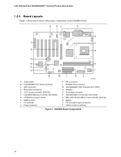
D845BG Board Components 14 Intel Desktop Board D845BG/D845PT Technical Product Specification 1.2.3 Board Layouts Figure 1 shows the location of the major components on the D845BG board. A BC D E T F S G R Q H P O I N M L K J OM12997 A Audio codec B Intel 82562ET PLC device (optional) C AGP connector D Back panel connectors E +12 V power connector (ATX12V) F Intel 82845 Memory Controller Hub (MCH) G µPGA478 processor socket H DIMM sockets...
D845BG Board Components 14 Intel Desktop Board D845BG/D845PT Technical Product Specification 1.2.3 Board Layouts Figure 1 shows the location of the major components on the D845BG board. A BC D E T F S G R Q H P O I N M L K J OM12997 A Audio codec B Intel 82562ET PLC device (optional) C AGP connector D Back panel connectors E +12 V power connector (ATX12V) F Intel 82845 Memory Controller Hub (MCH) G µPGA478 processor socket H DIMM sockets...
Product Specification
Page 15
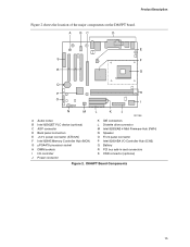
... components on the D845PT board. A BC D E S F R G Q P H O I N M L K J OM12986 A Audio codec B Intel 82562ET PLC device (optional) C AGP connector D Back panel connectors E +12 V power connector (ATX12V) F Intel 82845 Memory Controller Hub (MCH) G µPGA478 processor socket H DIMM sockets I I/O controller J Power connector K IDE connectors L Diskette drive connector M Intel 82802AB 4 Mbit Firmware Hub (FWH) N Speaker O Front panel connector P Intel 82801BA I/O Controller Hub...
... components on the D845PT board. A BC D E S F R G Q P H O I N M L K J OM12986 A Audio codec B Intel 82562ET PLC device (optional) C AGP connector D Back panel connectors E +12 V power connector (ATX12V) F Intel 82845 Memory Controller Hub (MCH) G µPGA478 processor socket H DIMM sockets I I/O controller J Power connector K IDE connectors L Diskette drive connector M Intel 82802AB 4 Mbit Firmware Hub (FWH) N Speaker O Front panel connector P Intel 82801BA I/O Controller Hub...
Product Specification
Page 16
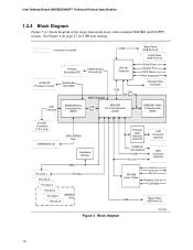
Block Diagram OM13008 16 Intel Desktop Board D845BG/D845PT Technical Product Specification 1.2.4 Block Diagram Figure 3 is a block diagram of the major functional areas of the standard D845BG and D845PT boards. See Figure 6 on page 27 for USB port routing. = connector or socket USB Primary/ ...MHz) AGP Interface 82845 Memory Controller Hub (MCH) 845 Chipset USB LPC Bus AHA Bus 82801BA I/O Controller Hub (ICH2) Back Panel USB Ports (2) Front Panel USB Ports (2) Serial Ports Parallel Port PS/2 Mouse PS/2 Keyboard Diskette Drive Connector 82802AB 4 Mbit Firmware Hub (FWH) 4X AGP...
Block Diagram OM13008 16 Intel Desktop Board D845BG/D845PT Technical Product Specification 1.2.4 Block Diagram Figure 3 is a block diagram of the major functional areas of the standard D845BG and D845PT boards. See Figure 6 on page 27 for USB port routing. = connector or socket USB Primary/ ...MHz) AGP Interface 82845 Memory Controller Hub (MCH) 845 Chipset USB LPC Bus AHA Bus 82801BA I/O Controller Hub (ICH2) Back Panel USB Ports (2) Front Panel USB Ports (2) Serial Ports Parallel Port PS/2 Mouse PS/2 Keyboard Diskette Drive Connector 82802AB 4 Mbit Firmware Hub (FWH) 4X AGP...

Product Specification
Page 17
... Connector AD1885 Audio Codec Line In Line Out Mic In Auxiliary Line In CD-ROM NEC µPD720100 USB 2.0 Host Controller USB USB Back Panel USB Ports (2) Front Panel USB Ports (2) Figure 4. Product Description Figure 4 is a block diagram of the major functional areas of the D845BG board with Optional USB 2.0 Support OM13009...
... Connector AD1885 Audio Codec Line In Line Out Mic In Auxiliary Line In CD-ROM NEC µPD720100 USB 2.0 Host Controller USB USB Back Panel USB Ports (2) Front Panel USB Ports (2) Figure 4. Product Description Figure 4 is a block diagram of the major functional areas of the D845BG board with Optional USB 2.0 Support OM13009...
Product Specification
Page 20
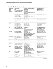
...Format Specification Front Panel I/O Connectivity Design Guide Low Pin Count Interface Specification microATX Motherboard Interface Specification OpenHCI - Revision 0.96, June 20, 2001, Intel Corporation. Version 1.0, December 1997, Intel Corporation. Version 1.0, October 2000, Intel Corporation. Revision ..., Institute of Electrical and Electronic Engineers. Revision 1.1, December 18, 1998, PCI Special Interest Group. Intel Desktop Board D845BG/D845PT Technical Product Specification Table 4. Revision 1.0, June 2000, JEDEC Solid State Technology Association. The information is...
...Format Specification Front Panel I/O Connectivity Design Guide Low Pin Count Interface Specification microATX Motherboard Interface Specification OpenHCI - Revision 0.96, June 20, 2001, Intel Corporation. Version 1.0, December 1997, Intel Corporation. Version 1.0, October 2000, Intel Corporation. Revision ..., Institute of Electrical and Electronic Engineers. Revision 1.1, December 18, 1998, PCI Special Interest Group. Intel Desktop Board D845BG/D845PT Technical Product Specification Table 4. Revision 1.0, June 2000, JEDEC Solid State Technology Association. The information is...
Product Specification
Page 27
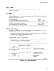
... 19, page 56 Figure 16, page 71 Table 42, page 72 Section 1.5, page 19 1.8.2.1 USB 1.1 Support The D845BG/D845PT boards support up to the audio connectors USB USB ports (2) Front panel USB connectors Figure 6. For information about The location of the USB connectors on the back...optional CNR add-in card USB USB ports (2) Back panel USB connectors adjacent to seven USB ports, as shown in Figure 6. Product Description 1.8.2 USB The following sections describe the USB port configurations implemented on the D845BG/D845PT boards. ✏ NOTE Computer systems that meets the ...
... 19, page 56 Figure 16, page 71 Table 42, page 72 Section 1.5, page 19 1.8.2.1 USB 1.1 Support The D845BG/D845PT boards support up to the audio connectors USB USB ports (2) Front panel USB connectors Figure 6. For information about The location of the USB connectors on the back...optional CNR add-in card USB USB ports (2) Back panel USB connectors adjacent to seven USB ports, as shown in Figure 6. Product Description 1.8.2 USB The following sections describe the USB port configurations implemented on the D845BG/D845PT boards. ✏ NOTE Computer systems that meets the ...
Product Specification
Page 28
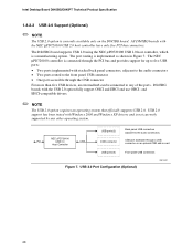
... controller is currently available only on an optional CNR add-in Figure 7. The port routing is implemented as shown in card Front panel USB connectors Figure 7. Intel Desktop Board D845BG/D845PT Technical Product Specification 1.8.2.2 USB 2.0 Support (Optional) ✏ NOTE The USB 2.0 option is connected through the PCI bus and provides support for up...
... controller is currently available only on an optional CNR add-in Figure 7. The port routing is implemented as shown in card Front panel USB connectors Figure 7. Intel Desktop Board D845BG/D845PT Technical Product Specification 1.8.2.2 USB 2.0 Support (Optional) ✏ NOTE The USB 2.0 option is connected through the PCI bus and provides support for up...

Product Specification
Page 31
... 57 Figure 16, page 71 Table 41, page 72 1.9.2 Parallel Port The 25-pin D-Sub parallel port connector is located on the back panel. The serial ports' NS16C550-compatible UART supports data transfers at speeds up to Figure 11, page 55 Table 20, page 56 Table 65, ...port connector Setting the parallel port's mode Refer to 115.2 kbits/sec with BIOS support. Product Description 1.9.1 Serial Ports The D845BG and D845PT boards have two serial port connectors. Serial port A is located on the back panel. Serial port B is accessible using a connector located near the main power connector.
... 57 Figure 16, page 71 Table 41, page 72 1.9.2 Parallel Port The 25-pin D-Sub parallel port connector is located on the back panel. The serial ports' NS16C550-compatible UART supports data transfers at speeds up to Figure 11, page 55 Table 20, page 56 Table 65, ...port connector Setting the parallel port's mode Refer to 115.2 kbits/sec with BIOS support. Product Description 1.9.1 Serial Ports The D845BG and D845PT boards have two serial port connectors. Serial port A is located on the back panel. Serial port B is accessible using a connector located near the main power connector.
Product Specification
Page 32
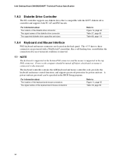
Power to these connectors are located on /reset. Intel Desktop Board D845BG/D845PT Technical Product Specification 1.9.3 Diskette Drive Controller The I/O controller supports one diskette drive that , like a self-healing fuse, reestablishes the connection after an ... the AMI keyboard and mouse controller code, provides the keyboard and mouse control functions, and supports password protection for power-on the back panel. For information about The location of the keyboard and mouse connectors The signal names of the diskette drive connector The supported diskette drive capacities...
Power to these connectors are located on /reset. Intel Desktop Board D845BG/D845PT Technical Product Specification 1.9.3 Diskette Drive Controller The I/O controller supports one diskette drive that , like a self-healing fuse, reestablishes the connection after an ... the AMI keyboard and mouse controller code, provides the keyboard and mouse control functions, and supports password protection for power-on the back panel. For information about The location of the keyboard and mouse connectors The signal names of the diskette drive connector The supported diskette drive capacities...
Product Specification
Page 33
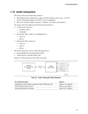
Audio Subsystem Block Diagram OM13010 For information about Upgrading the onboard audio subsystem using a CNR audio card The front panel audio connector The back panel audio connectors Refer to -noise) ratio: ≥ 85 dB • Power management support for ACPI 2.0 (driver ... the following audio interfaces: • ATAPI-style connectors: Auxiliary line in The audio subsystem consists of the following devices: • Intel 82801BA I/O Controller Hub (ICH2) • Analog Devices AD1885 audio codec Figure 8 is a block diagram of the audio subsystem. 82801BA I/O Controller...
Audio Subsystem Block Diagram OM13010 For information about Upgrading the onboard audio subsystem using a CNR audio card The front panel audio connector The back panel audio connectors Refer to -noise) ratio: ≥ 85 dB • Power management support for ACPI 2.0 (driver ... the following audio interfaces: • ATAPI-style connectors: Auxiliary line in The audio subsystem consists of the following devices: • Intel 82801BA I/O Controller Hub (ICH2) • Analog Devices AD1885 audio codec Figure 8 is a block diagram of the audio subsystem. 82801BA I/O Controller...
Product Specification
Page 34
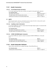
... connector Table 40, page 72 Obtaining the Front Panel I/O Connectivity Design Guide Section 1.5, page 19 ✏ NOTE The front panel audio connector is alternately used as a jumper block for front panel audio connectors. Intel Desktop Board D845BG/D845PT Technical Product Specification 1.10.1 Audio Connectors 1.10.1.1 Front Panel Audio Connector A 2 x 5-pin connector provides mic in connector Refer...
... connector Table 40, page 72 Obtaining the Front Panel I/O Connectivity Design Guide Section 1.5, page 19 ✏ NOTE The front panel audio connector is alternately used as a jumper block for front panel audio connectors. Intel Desktop Board D845BG/D845PT Technical Product Specification 1.10.1 Audio Connectors 1.10.1.1 Front Panel Audio Connector A 2 x 5-pin connector provides mic in connector Refer...

Product Specification
Page 35
...LAN Connector LED States LED Color LED State Condition Green Off 10 Mbit/sec data rate is communicating with another computer on the back panel • Full device driver compatibility • ACPI support • Programmable transit threshold • Configuration EEPROM that supports the 82562ET (10...) on the CNR bus • PCI Power Management Supports ACPI technology Supports LAN wake capabilities 1.11.1 Intel® 82562ET Platform LAN Connect Device The Intel 82562ET component provides an interface to the back panel RJ-45 connector with integrated LEDs.
...LAN Connector LED States LED Color LED State Condition Green Off 10 Mbit/sec data rate is communicating with another computer on the back panel • Full device driver compatibility • ACPI support • Programmable transit threshold • Configuration EEPROM that supports the 82562ET (10...) on the CNR bus • PCI Power Management Supports ACPI technology Supports LAN wake capabilities 1.11.1 Intel® 82562ET Platform LAN Connect Device The Intel 82562ET component provides an interface to the back panel RJ-45 connector with integrated LEDs.

Product Specification
Page 38
... bus and device enumeration) • Power management control of ACPI with the D845BG and D845PT boards requires an operating system that detects if the chassis cover is closed for a front panel power and sleep mode switch 38 The security feature uses a mechanical switch on page 41... Management Event (PME#) wake-up events (see Table 10 on the chassis that enables the operating system to AC power. Intel Desktop Board D845BG/D845PT Technical Product Specification 1.13.3 Chassis Intrusion and Detection The boards support a chassis security feature that provides full ACPI support. The...
... bus and device enumeration) • Power management control of ACPI with the D845BG and D845PT boards requires an operating system that detects if the chassis cover is closed for a front panel power and sleep mode switch 38 The security feature uses a mechanical switch on page 41... Management Event (PME#) wake-up events (see Table 10 on the chassis that enables the operating system to AC power. Intel Desktop Board D845BG/D845PT Technical Product Specification 1.13.3 Chassis Intrusion and Detection The boards support a chassis security feature that provides full ACPI support. The...

Product Specification
Page 41
... ACPI state requires an operating system that do not use of these wake-up the computer... Power switch RTC alarm LAN CNR PME# Modem (back panel Serial Port A) USB PS/2 devices ...from this option to configure devices that provides full ACPI support. Table 10. For LAN and PME#, S5 is used...
... ACPI state requires an operating system that do not use of these wake-up the computer... Power switch RTC alarm LAN CNR PME# Modem (back panel Serial Port A) USB PS/2 devices ...from this option to configure devices that provides full ACPI support. Table 10. For LAN and PME#, S5 is used...
Product Specification
Page 44
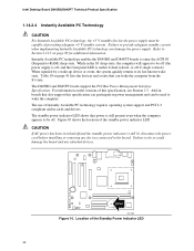
...or off if single colored.) When signaled by a wake-up device or event, the system quickly returns to its last known wake state. Intel Desktop Board D845BG/D845PT Technical Product Specification 1.14.2.4 Instantly Available PC Technology CAUTION For Instantly Available PC technology, the +5 V standby line for additional information. For ... board. While in the S3 sleep-state, the computer will appear to be off (the power supply is off, and the front panel LED is still present even when the computer appears to be off and the standby power indicator is still lit, disconnect the power cord...
...or off if single colored.) When signaled by a wake-up device or event, the system quickly returns to its last known wake state. Intel Desktop Board D845BG/D845PT Technical Product Specification 1.14.2.4 Instantly Available PC Technology CAUTION For Instantly Available PC technology, the +5 V standby line for additional information. For ... board. While in the S3 sleep-state, the computer will appear to be off (the power supply is off, and the front panel LED is still present even when the computer appears to be off and the standby power indicator is still lit, disconnect the power cord...
Product Specification
Page 54
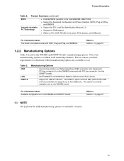
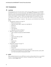
...Intel Desktop Board D845BG/D845PT Technical Product Specification 2.8 Connectors CAUTION Only the back panel, the front panel audio, and the front panel USB connectors of the D845BG and D845PT boards have overcurrent protection. Do not use these connectors to power devices external to the computer, the interconnecting cable, and the external devices themselves. The D845BG and D845PT... such as fans and internal peripherals. The connectors can be divided into the following groups: • Back panel I/O connectors (see page 55) PS/2 keyboard and mouse USB (four with the ...
...Intel Desktop Board D845BG/D845PT Technical Product Specification 2.8 Connectors CAUTION Only the back panel, the front panel audio, and the front panel USB connectors of the D845BG and D845PT boards have overcurrent protection. Do not use these connectors to power devices external to the computer, the interconnecting cable, and the external devices themselves. The D845BG and D845PT... such as fans and internal peripherals. The connectors can be divided into the following groups: • Back panel I/O connectors (see page 55) PS/2 keyboard and mouse USB (four with the ...


