
Product Specification
Page 5
...14 1.1.4 Block Diagram 15 1.2 Online Support ...16 1.3 Operating System Support 16 1.4 Design Specifications 17 1.5 Processor ...20 1.6 System Memory ...21 1.7 Intel® 845PE Chipset 23 1.7.1 AGP ...24 1.7.2 USB...24 1.7.3 IDE Support 25 1.7.4 Real-Time Clock, CMOS SRAM, and Battery 26 1.7.5 Intel® 82802AB ...2-Channel Audio Subsystem (Optional 31 1.12.3 Audio Connectors 32 1.12.4 Audio Subsystem Software 32 1.13 LAN Subsystem...33 1.13.1 Intel® 82562ET Physical Layer Interface Device 33 1.13.2 RJ-45 LAN Connector with Integrated LEDs 33 1.13.3 LAN Subsystem Software 34 ...
...14 1.1.4 Block Diagram 15 1.2 Online Support ...16 1.3 Operating System Support 16 1.4 Design Specifications 17 1.5 Processor ...20 1.6 System Memory ...21 1.7 Intel® 845PE Chipset 23 1.7.1 AGP ...24 1.7.2 USB...24 1.7.3 IDE Support 25 1.7.4 Real-Time Clock, CMOS SRAM, and Battery 26 1.7.5 Intel® 82802AB ...2-Channel Audio Subsystem (Optional 31 1.12.3 Audio Connectors 32 1.12.4 Audio Subsystem Software 32 1.13 LAN Subsystem...33 1.13.1 Intel® 82562ET Physical Layer Interface Device 33 1.13.2 RJ-45 LAN Connector with Integrated LEDs 33 1.13.3 LAN Subsystem Software 34 ...
Product Specification
Page 8
... 40 9. Localized High Temperature Zones 84 Tables 1. IEEE 1394a-2000 Connector (Optional 53 18. Location of Pressing the Power Switch 38 7. Supported Memory Configurations 22 5. Intel 845PE Chipset Block Diagram 23 4. Desktop Board D845PEBT2 Components 14 2. Interrupts ...48 15. PCI Interrupt Routing Map 50 16. External I/O Connectors 68 16...
... 40 9. Localized High Temperature Zones 84 Tables 1. IEEE 1394a-2000 Connector (Optional 53 18. Location of Pressing the Power Switch 38 7. Supported Memory Configurations 22 5. Intel 845PE Chipset Block Diagram 23 4. Desktop Board D845PEBT2 Components 14 2. Interrupts ...48 15. PCI Interrupt Routing Map 50 16. External I/O Connectors 68 16...
Product Specification
Page 15
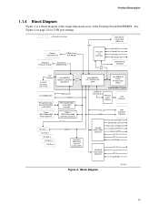
... the major functional areas of the Desktop Board D845PEBT2. Block Diagram OM15028 15 See Figure 4 on page 24 for USB port routing. = connector or socket Primary/ Secondary IDE UDMA 33 and ATA-66/100 mPGA478 Processor ... LPC Bus Back Panel/ Front Panel USB Ports Serial Port Parallel Port PS/2 Mouse PS/2 Keyboard Diskette Drive Connector AGP Interface 4X AGP Connector (1.5 V only) Intel 82845PE Memory Controller Hub (MCH) AHA Bus Two DIMM Banks Primary/Secondary SATA/SATA RAID or IDE RAID Three IEEE 1394a-2000 Ports (Optional) Memory...
... the major functional areas of the Desktop Board D845PEBT2. Block Diagram OM15028 15 See Figure 4 on page 24 for USB port routing. = connector or socket Primary/ Secondary IDE UDMA 33 and ATA-66/100 mPGA478 Processor ... LPC Bus Back Panel/ Front Panel USB Ports Serial Port Parallel Port PS/2 Mouse PS/2 Keyboard Diskette Drive Connector AGP Interface 4X AGP Connector (1.5 V only) Intel 82845PE Memory Controller Hub (MCH) AHA Bus Two DIMM Banks Primary/Secondary SATA/SATA RAID or IDE RAID Three IEEE 1394a-2000 Ports (Optional) Memory...
Product Specification
Page 23
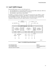
...82845PE Memory Controller Hub (MCH) AHA Bus 82801DB I /O paths. Intel 845PE Chipset Block Diagram OM15029 For information about The Intel 845PE chipset Resources used by the chipset Refer to http://developer.intel.com Chapter 2 23 The component combination provides the chipset interfaces as ... with AHA bus • Intel 82802AB (4 Mbit) Firmware Hub (FWH) The MCH is a centralized controller for the system bus, the memory bus, the AGP bus, and the Accelerated Hub Architecture interface. The ICH4 is a centralized controller for the Desktop Board D845PEBT2's I /O Controller Hub (ICH4...
...82845PE Memory Controller Hub (MCH) AHA Bus 82801DB I /O paths. Intel 845PE Chipset Block Diagram OM15029 For information about The Intel 845PE chipset Resources used by the chipset Refer to http://developer.intel.com Chapter 2 23 The component combination provides the chipset interfaces as ... with AHA bus • Intel 82802AB (4 Mbit) Firmware Hub (FWH) The MCH is a centralized controller for the system bus, the memory bus, the AGP bus, and the Accelerated Hub Architecture interface. The ICH4 is a centralized controller for the Desktop Board D845PEBT2's I /O Controller Hub (ICH4...
Product Specification
Page 31
...Out Rear Left and Right Out Digital S/PDIF Optical S/PDIF Line In Mic In CD-ROM Figure 5. 6-Channel Audio Subsystem Block Diagram OM15030 For information about The front panel audio connector The back panel audio connectors Refer to Section 2.8.3, page 68 Section 2.8.1, page 52... 1.12.2 2-Channel Audio Subsystem (Optional) The audio subsystem includes the following: • Intel 82801DB I/O Controller Hub (ICH4) • Analog Devices AD1981B audio codec • Microphone input that supports a single dynamic, condenser, or electret ...
...Out Rear Left and Right Out Digital S/PDIF Optical S/PDIF Line In Mic In CD-ROM Figure 5. 6-Channel Audio Subsystem Block Diagram OM15030 For information about The front panel audio connector The back panel audio connectors Refer to Section 2.8.3, page 68 Section 2.8.1, page 52... 1.12.2 2-Channel Audio Subsystem (Optional) The audio subsystem includes the following: • Intel 82801DB I/O Controller Hub (ICH4) • Analog Devices AD1981B audio codec • Microphone input that supports a single dynamic, condenser, or electret ...
Product Specification
Page 32
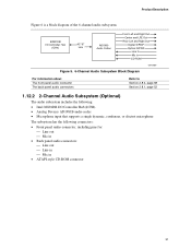
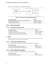
Intel Desktop Board D845PEBT2 Technical Product Specification Figure 6 is a block diagram of the front panel audio connector Table 45, page 69 Obtaining the Front Panel I /O Controller Hub (ICH4) AC '97 Link AD1981B Audio Codec Line In Line Out Mic In CD-ROM OM15031 Figure 6. 2-Channel Audio Subsystem Block Diagram For information about Upgrading the onboard...
Intel Desktop Board D845PEBT2 Technical Product Specification Figure 6 is a block diagram of the front panel audio connector Table 45, page 69 Obtaining the Front Panel I /O Controller Hub (ICH4) AC '97 Link AD1981B Audio Codec Line In Line Out Mic In CD-ROM OM15031 Figure 6. 2-Channel Audio Subsystem Block Diagram For information about Upgrading the onboard...


