Product Guide
Page 3
Contents 1 Desktop Board Features Desktop Board Components 9 Processor ...10 Main Memory ...11 Intel® 845GV Chipset ...11 Intel® 82845GV Graphics and Memory Controller Hub (GMCH 12 Intel® 82801DB I/O Controller Hub (ICH4 12 Firmware Hub (FWH 12 Input/Output (I/O) Controller 12 ...Integrated Graphics...13 LAN Subsystem (Optional 13 LAN Subsystem Software 13 RJ-45 LAN Connector LEDs 14 Hi-Speed USB 2.0 Support 14 Enhanced IDE Interface ...14 Expansion Slots...15 BIOS...
Contents 1 Desktop Board Features Desktop Board Components 9 Processor ...10 Main Memory ...11 Intel® 845GV Chipset ...11 Intel® 82845GV Graphics and Memory Controller Hub (GMCH 12 Intel® 82801DB I/O Controller Hub (ICH4 12 Firmware Hub (FWH 12 Input/Output (I/O) Controller 12 ...Integrated Graphics...13 LAN Subsystem (Optional 13 LAN Subsystem Software 13 RJ-45 LAN Connector LEDs 14 Hi-Speed USB 2.0 Support 14 Enhanced IDE Interface ...14 Expansion Slots...15 BIOS...
Product Guide
Page 4
Intel Desktop Board D845GVAD2 Product Guide Installing and Removing Memory 24 Installing DIMMs ...24 Removing DIMMs ...25 Connecting the IDE Cable 25 Connecting the Front Panel Header 27 Installing a Front Panel Audio Solution (Optional 27 Installing a Front Panel USB Solution 27 Setting the BIOS Configuration Jumper Block 28 Clearing Passwords ...29 Replacing the Battery...
Intel Desktop Board D845GVAD2 Product Guide Installing and Removing Memory 24 Installing DIMMs ...24 Removing DIMMs ...25 Connecting the IDE Cable 25 Connecting the Front Panel Header 27 Installing a Front Panel Audio Solution (Optional 27 Installing a Front Panel USB Solution 27 Setting the BIOS Configuration Jumper Block 28 Clearing Passwords ...29 Replacing the Battery...
Product Guide
Page 5
Desktop Board Components 9 2. Location of the BIOS Configuration Jumper Block 28 10. Connecting the IDE Cable 26 9. Add-in Card and Peripheral Interface Connectors 63 15. Installing a Processor...22 6.... Connectors 63 Front Panel Headers 64 Desktop Board Resources 66 Memory Map ...66 DMA Channels ...66 Interrupts ...67 A Error Messages and Indicators BIOS Beep Codes ...69 BIOS Error Messages ...70 B Regulatory Compliance Safety Regulations ...73 EMC Regulations ...73 Product Certification Markings 74 Installation Instructions...75 Ensure Electromagnetic Compatibility (EMC...
Desktop Board Components 9 2. Location of the BIOS Configuration Jumper Block 28 10. Connecting the IDE Cable 26 9. Add-in Card and Peripheral Interface Connectors 63 15. Installing a Processor...22 6.... Connectors 63 Front Panel Headers 64 Desktop Board Resources 66 Memory Map ...66 DMA Channels ...66 Interrupts ...67 A Error Messages and Indicators BIOS Beep Codes ...69 BIOS Error Messages ...70 B Regulatory Compliance Safety Regulations ...73 EMC Regulations ...73 Product Certification Markings 74 Installation Instructions...75 Ensure Electromagnetic Compatibility (EMC...
Product Guide
Page 6
...67 35. Diskette Configuration Submenu 48 16. Power Menu...54 22. ACPI Submenu ...54 23. Boot Device Priority Submenu 56 25. BIOS Error Messages 70 37. RJ-45 LAN Connector LEDs 14 4. Main Menu...39 9. Hard Disk Drives Submenu 56 26. Beep Codes ...69 36...53 21. Front Panel Header (J9G1 65 32. PCI Configuration Submenu 41 11. BIOS Setup Program Menu Bar 37 6. Feature Summary ...7 2. Boot Menu ...55 24. Removable Devices Submenu 57 27. EMC Regulations ...73 vi Intel Desktop Board D845GVAD2 Product Guide Tables 1. ATAPI CD-ROM Drives Submenu 57 28.
...67 35. Diskette Configuration Submenu 48 16. Power Menu...54 22. ACPI Submenu ...54 23. Boot Device Priority Submenu 56 25. BIOS Error Messages 70 37. RJ-45 LAN Connector LEDs 14 4. Main Menu...39 9. Hard Disk Drives Submenu 56 26. Beep Codes ...69 36...53 21. Front Panel Header (J9G1 65 32. PCI Configuration Submenu 41 11. BIOS Setup Program Menu Bar 37 6. Feature Summary ...7 2. Boot Menu ...55 24. Removable Devices Submenu 57 27. EMC Regulations ...73 vi Intel Desktop Board D845GVAD2 Product Guide Tables 1. ATAPI CD-ROM Drives Submenu 57 28.
Product Guide
Page 8
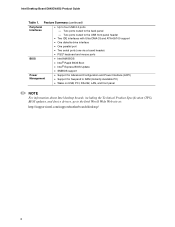
... via a board header) • PS/2† keyboard and mouse ports BIOS • Intel/AMI BIOS • Intel® Rapid BIOS Boot • Intel® Express BIOS Update • SMBIOS support Power Management • Support for Advanced Configuration and...Intel desktop boards, including the Technical Product Specification (TPS), BIOS updates, and device drivers, go to four USB 2.0 ports - Intel Desktop Board D845GVAD2 Product Guide Table 1. Feature Summary (continued) Peripheral Interfaces • Up to the Intel World Wide Web site at: http://support.intel.com/support/motherboards...
... via a board header) • PS/2† keyboard and mouse ports BIOS • Intel/AMI BIOS • Intel® Rapid BIOS Boot • Intel® Express BIOS Update • SMBIOS support Power Management • Support for Advanced Configuration and...Intel desktop boards, including the Technical Product Specification (TPS), BIOS updates, and device drivers, go to four USB 2.0 ports - Intel Desktop Board D845GVAD2 Product Guide Table 1. Feature Summary (continued) Peripheral Interfaces • Up to the Intel World Wide Web site at: http://support.intel.com/support/motherboards...
Product Guide
Page 9
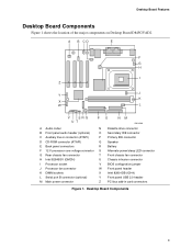
... major components on Desktop Board D845GVAD2. A B CD E F G H I Z J Y K X W L V SRQ UT PO NM OM14568 A Audio codec N B Front panel audio header (optional) O C Auxiliary line-in connector (ATAPI) P D CD-ROM connector (ATAPI) Q E Back panel connectors R F 12 V processor core voltage connector S G Rear chassis fan connector T H Intel 82845GV (GMCH) U I Processor socket V J Processor fan connector W K DIMM sockets X L Serial port B connector (optional...
... major components on Desktop Board D845GVAD2. A B CD E F G H I Z J Y K X W L V SRQ UT PO NM OM14568 A Audio codec N B Front panel audio header (optional) O C Auxiliary line-in connector (ATAPI) P D CD-ROM connector (ATAPI) Q E Back panel connectors R F 12 V processor core voltage connector S G Rear chassis fan connector T H Intel 82845GV (GMCH) U I Processor socket V J Processor fan connector W K DIMM sockets X L Serial port B connector (optional...
Product Guide
Page 11
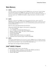
...NOTE Desktop Board D845GVAD2 has been designed to support DIMMs based on 512 Mbit technology up to 2 GB, but this technology has not been validated on this effect on the screen at : http://support.intel.com/support/motherboards/desktop/ Intel® 845GV Chipset The Intel 845GV chipset consists ... information about the latest list of the following: • Intel 82845GV Graphics and Memory Controller Hub (GMCH) with AHA bus • Intel 82801DB I/O Controller Hub (ICH4) with AHA bus • Firmware Hub (FWH) 11 The BIOS will see a notification to configure the memory controller for normal...
...NOTE Desktop Board D845GVAD2 has been designed to support DIMMs based on 512 Mbit technology up to 2 GB, but this technology has not been validated on this effect on the screen at : http://support.intel.com/support/motherboards/desktop/ Intel® 845GV Chipset The Intel 845GV chipset consists ... information about the latest list of the following: • Intel 82845GV Graphics and Memory Controller Hub (GMCH) with AHA bus • Intel 82801DB I/O Controller Hub (ICH4) with AHA bus • Firmware Hub (FWH) 11 The BIOS will see a notification to configure the memory controller for normal...
Product Guide
Page 12
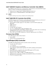
...management support 12 Features on this desktop board. Intel Desktop Board D845GVAD2 Product Guide Intel® 82845GV Graphics and Memory Controller Hub (GMCH) The GMCH provides the processor, system memory, and hub interfaces in the Intel 845GV chipset platform. Intel® 82801DB I/O Controller Hub (ICH4) ... host controllers supporting up to four USB ports Firmware Hub (FWH) The 4 Mbit Firmware Hub has these features: • System BIOS • System security and management logic Input/Output (I/O) Controller The SMSC LPC47M102S-MC ultra I/O controller features the following: • ...
...management support 12 Features on this desktop board. Intel Desktop Board D845GVAD2 Product Guide Intel® 82845GV Graphics and Memory Controller Hub (GMCH) The GMCH provides the processor, system memory, and hub interfaces in the Intel 845GV chipset platform. Intel® 82801DB I/O Controller Hub (ICH4) ... host controllers supporting up to four USB ports Firmware Hub (FWH) The 4 Mbit Firmware Hub has these features: • System BIOS • System security and management logic Input/Output (I/O) Controller The SMSC LPC47M102S-MC ultra I/O controller features the following: • ...
Product Guide
Page 14
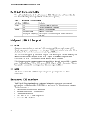
...) On (brighter and pulsing) Indicates 10 Mbit/sec data rate is selected. 100 Mbit/sec data rate is established. Disabling Hi-Speed USB in BIOS reverts all USB 2.0 ports to four IDE devices (such as hard drives) • ATAPI devices (such as CD-ROM drives) • Older...LAN link is selected. The interface supports: • Up to USB 1.1 operation. This may be required to four USB 2.0 ports via ICH4; Intel Desktop Board D845GVAD2 Product Guide RJ-45 LAN Connector LEDs Two LEDs are backward compatible with another computer on the LAN. Table 3 describes the LED states when...
...) On (brighter and pulsing) Indicates 10 Mbit/sec data rate is selected. 100 Mbit/sec data rate is established. Disabling Hi-Speed USB in BIOS reverts all USB 2.0 ports to four IDE devices (such as hard drives) • ATAPI devices (such as CD-ROM drives) • Older...LAN link is selected. The interface supports: • Up to USB 1.1 operation. This may be required to four USB 2.0 ports via ICH4; Intel Desktop Board D845GVAD2 Product Guide RJ-45 LAN Connector LEDs Two LEDs are backward compatible with another computer on the LAN. Table 3 describes the LED states when...
Product Guide
Page 15
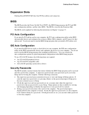
...supervisor or user password was entered. • Setting a user password restricts who can be updated by specifying manual configuration in the BIOS automatically detects and configures the device for booting the computer, with the following restrictions: • The supervisor password gives unrestricted access... Board Features Expansion Slots Desktop Board D845GVAD2 has four PCI bus add-in the Firmware Hub. BIOS The BIOS provides the Power-On Self-Test (POST), the BIOS Setup program, the PCI and IDE auto-configuration utilities, and the video BIOS. If only the supervisor password is...
...supervisor or user password was entered. • Setting a user password restricts who can be updated by specifying manual configuration in the BIOS automatically detects and configures the device for booting the computer, with the following restrictions: • The supervisor password gives unrestricted access... Board Features Expansion Slots Desktop Board D845GVAD2 has four PCI bus add-in the Firmware Hub. BIOS The BIOS provides the Power-On Self-Test (POST), the BIOS Setup program, the PCI and IDE auto-configuration utilities, and the video BIOS. If only the supervisor password is...
Product Guide
Page 19
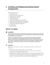
... panel header (not included) • Install the front panel audio solution (not included) • Install the front panel USB solution (not included) • Set the BIOS configuration jumper block • Clear passwords • Replace the battery Before You Begin WARNINGS The procedures in this chapter. Perform the procedures described in personal...
... panel header (not included) • Install the front panel audio solution (not included) • Install the front panel USB solution (not included) • Set the BIOS configuration jumper block • Clear passwords • Replace the battery Before You Begin WARNINGS The procedures in this chapter. Perform the procedures described in personal...
Product Guide
Page 28
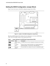
... the jumper settings for booting. Recovery (None) Recovers BIOS from a diskette in the event of the BIOS Configuration Jumper Block The three-pin BIOS jumper block enables all board configurations to clear passwords. Location of a failed BIOS update. 28 Intel Desktop Board D845GVAD2 Product Guide Setting the BIOS Configuration Jumper Block Figure 9 shows the location of the...
... the jumper settings for booting. Recovery (None) Recovers BIOS from a diskette in the event of the BIOS Configuration Jumper Block The three-pin BIOS jumper block enables all board configurations to clear passwords. Location of a failed BIOS update. 28 Intel Desktop Board D845GVAD2 Product Guide Setting the BIOS Configuration Jumper Block Figure 9 shows the location of the...
Product Guide
Page 29
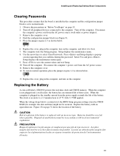
... computer. To restore normal operation, place the jumper on pins 2-3 as shown below a certain level, the BIOS Setup program settings stored in accordance with an incorrect type. When the computer is not plugged into a wall socket, the battery has an estimated life of used batteries must be in CMOS RAM (for example...
... computer. To restore normal operation, place the jumper on pins 2-3 as shown below a certain level, the BIOS Setup program settings stored in accordance with an incorrect type. When the computer is not plugged into a wall socket, the battery has an estimated life of used batteries must be in CMOS RAM (for example...
Product Guide
Page 33
...: http://support.intel.com/support/motherboards/desktop 33 Obtaining the BIOS Update File You can also save this file to update the BIOS. The BIOS update file is useful if you need to a diskette. Navigate to your hard drive where it was saved. This runs the update program. 6. Download the file to the D845GVAD2 page and...
...: http://support.intel.com/support/motherboards/desktop 33 Obtaining the BIOS Update File You can also save this file to update the BIOS. The BIOS update file is useful if you need to a diskette. Navigate to your hard drive where it was saved. This runs the update program. 6. Download the file to the D845GVAD2 page and...
Product Guide
Page 34
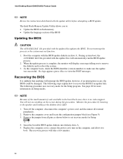
... system. 3. As the computer boots, check the BIOS identifier (version number) to : • Update the BIOS in flash memory • Update the language section of code available in drive A. Intel Desktop Board D845GVAD2 Product Guide ✏ NOTE Review the instructions distributed with... the update files updates the BIOS. The Intel Flash Memory Update Utility allows you to remove the diskette and to...
... system. 3. As the computer boots, check the BIOS identifier (version number) to : • Update the BIOS in flash memory • Update the language section of code available in drive A. Intel Desktop Board D845GVAD2 Product Guide ✏ NOTE Review the instructions distributed with... the update files updates the BIOS. The Intel Flash Memory Update Utility allows you to remove the diskette and to...
Product Guide
Page 35
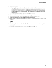
...begin to step 1 and repeat the recovery process. 8. If recovery fails, return to show activity. Remove the computer cover and continue with the BIOS update (see page 34). 35 Turn on pins 1-2 as shown below to set normal mode for Setup. 31 11. Drive A activity will begin..., reinstall the jumper back on the computer and continue with the following steps. 10. This sequence of events indicates a successful BIOS recovery. • A series of the BIOS core. Leave the update diskette in drive A, replace the computer cover, and connect the computer's power cord. 12. In about...
...begin to step 1 and repeat the recovery process. 8. If recovery fails, return to show activity. Remove the computer cover and continue with the BIOS update (see page 34). 35 Turn on pins 1-2 as shown below to set normal mode for Setup. 31 11. Drive A activity will begin..., reinstall the jumper back on the computer and continue with the following steps. 10. This sequence of events indicates a successful BIOS recovery. • A series of the BIOS core. Leave the update diskette in drive A, replace the computer cover, and connect the computer's power cord. 12. In about...
Product Guide
Page 37
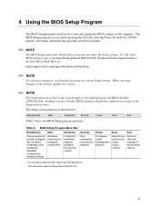
...) memory test begins and before the operating system boot begins. ✏ NOTE The BIOS Setup menus described in this section apply to the Intel Desktop Board D845GVAD2 Technical Product Specification or the Intel World Wide Web site: http://support.intel.com/support/motherboards/desktop ✏ NOTE For reference purposes, you make changes to the settings, update...
...) memory test begins and before the operating system boot begins. ✏ NOTE The BIOS Setup menus described in this section apply to the Intel Desktop Board D845GVAD2 Technical Product Specification or the Intel World Wide Web site: http://support.intel.com/support/motherboards/desktop ✏ NOTE For reference purposes, you make changes to the settings, update...
Product Guide
Page 38
... information about setting configure mode. Clears the Wired for menu screens. BIOS Setup Program Function Keys BIOS Setup Program Function Key or or Description Selects a different menu screen Moves cursor up or down Moves cursor to clear the Setup passwords. Intel Desktop Board D845GVAD2 Product Guide Table 6 shows the function keys available for Management...
... information about setting configure mode. Clears the Wired for menu screens. BIOS Setup Program Function Keys BIOS Setup Program Function Key or or Description Selects a different menu screen Moves cursor up or down Moves cursor to clear the Setup passwords. Intel Desktop Board D845GVAD2 Product Guide Table 6 shows the function keys available for Management...

Product Guide
Page 39
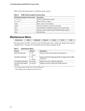
..., and second Day of week Month/day/year Description Displays the version of second-level cache and whether it is used by the BIOS. Displays the amount and type of RAM. Selects the current default language used to configure the system date and system time. Table ...8. Displays the system bus speed. Specifies the current date. 39 Displays processor speed. Specifies the current time. Using the BIOS Setup Program Main Menu Maintenance Main Advanced Security Power Boot Exit Table 8 describes the Main Menu. Displays processor type. Displays the total amount...
..., and second Day of week Month/day/year Description Displays the version of second-level cache and whether it is used by the BIOS. Displays the amount and type of RAM. Selects the current default language used to configure the system date and system time. Table ...8. Displays the system bus speed. Specifies the current date. 39 Displays processor speed. Specifies the current time. Using the BIOS Setup Program Main Menu Maintenance Main Advanced Security Power Boot Exit Table 8 describes the Main Menu. Displays processor type. Displays the total amount...
Product Guide
Page 41
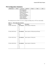
... IRQ priority. 41 Allows selection of IRQ priority. Table 10. Allows selection of IRQ priority and S5 wake. Allows selection of IRQ priority. Using the BIOS Setup Program PCI Configuration Submenu Maintenance Main Advanced Security Power Boot Exit PCI Configuration Boot Configuration Peripheral Configuration IDE Configuration Diskette Configuration Event Log Configuration...
... IRQ priority. 41 Allows selection of IRQ priority. Table 10. Allows selection of IRQ priority and S5 wake. Allows selection of IRQ priority. Using the BIOS Setup Program PCI Configuration Submenu Maintenance Main Advanced Security Power Boot Exit PCI Configuration Boot Configuration Peripheral Configuration IDE Configuration Diskette Configuration Event Log Configuration...


