Product Guide
Page 3
...Support 15 Enhanced IDE Interface ...16 Expansion Slots...16 Accelerated Graphics Port (AGP 16 Communication and Networking Riser (CNR) (Optional 16 BIOS ...17 PCI Auto Configuration 17 IDE Auto Configuration 17 Security Passwords ...17 Power Management Features 17 ACPI ...18 Suspend to RAM (Instantly... ...19 Fan Speed Control (Intel® Precision Cooling Technology 19 Resume on Ring...20 Wake from USB...20 Wake from PS/2 Keyboard/Mouse 20 PME# Wakeup Support 20 Speaker...20 Battery...20 Real-Time Clock...20 2 Installing and Replacing Desktop Board Components Before You Begin ...21...
...Support 15 Enhanced IDE Interface ...16 Expansion Slots...16 Accelerated Graphics Port (AGP 16 Communication and Networking Riser (CNR) (Optional 16 BIOS ...17 PCI Auto Configuration 17 IDE Auto Configuration 17 Security Passwords ...17 Power Management Features 17 ACPI ...18 Suspend to RAM (Instantly... ...19 Fan Speed Control (Intel® Precision Cooling Technology 19 Resume on Ring...20 Wake from USB...20 Wake from PS/2 Keyboard/Mouse 20 PME# Wakeup Support 20 Speaker...20 Battery...20 Real-Time Clock...20 2 Installing and Replacing Desktop Board Components Before You Begin ...21...
Product Guide
Page 4
Intel Desktop Boards D845GERG2 and D845GEBV2 Product Guide Installing a Processor 24 Installing the Processor Fan Heat Sink 24 Connecting the Processor Fan Heat Sink Cable 25 Removing the Processor ... Clearing Passwords ...35 Replacing the Battery ...36 3 Updating the BIOS Updating the BIOS with the Intel® Express BIOS Update Utility 39 Updating the BIOS with the Intel® Flash Memory Update Utility 40 Obtaining the BIOS Update File 40 Updating the BIOS...40 Recovering the BIOS 41 4 Using the BIOS Setup Program Maintenance Menu...44 Main Menu ...45 Advanced...
Intel Desktop Boards D845GERG2 and D845GEBV2 Product Guide Installing a Processor 24 Installing the Processor Fan Heat Sink 24 Connecting the Processor Fan Heat Sink Cable 25 Removing the Processor ... Clearing Passwords ...35 Replacing the Battery ...36 3 Updating the BIOS Updating the BIOS with the Intel® Express BIOS Update Utility 39 Updating the BIOS with the Intel® Flash Memory Update Utility 40 Obtaining the BIOS Update File 40 Updating the BIOS...40 Recovering the BIOS 41 4 Using the BIOS Setup Program Maintenance Menu...44 Main Menu ...45 Advanced...
Product Guide
Page 5
...76 Place Battery Marking 76 Use Only for Intended Applications 76 Figures 1. Location of Desktop Board Mounting Holes 23 6. Location of the BIOS Configuration Jumper Block 34 14. Installing a Memory Module 26 9. Connecting the Processor Fan... Heat Sink Cable to the Processor Fan Connector ........25 8. Connecting the IDE Cable 29 11. Location of Standby Power Indicator 18 4. Desktop Board D845GEBV2 Components 10 3. Removing the AGP or ADD Card 28 10. Desktop Board D845GERG2...
...76 Place Battery Marking 76 Use Only for Intended Applications 76 Figures 1. Location of Desktop Board Mounting Holes 23 6. Location of the BIOS Configuration Jumper Block 34 14. Installing a Memory Module 26 9. Connecting the Processor Fan... Heat Sink Cable to the Processor Fan Connector ........25 8. Connecting the IDE Cable 29 11. Location of Standby Power Indicator 18 4. Desktop Board D845GEBV2 Components 10 3. Removing the AGP or ADD Card 28 10. Desktop Board D845GERG2...
Product Guide
Page 6
Intel Desktop Boards D845GERG2 and D845GEBV2 Product Guide 15. RJ-45 10/100 Ethernet LAN Connector...Main Menu...45 13. Removable Devices Submenu 60 32. Back Panel Connectors 64 16. Supported Processors 11 3. BIOS Setup Program Menu Bar 43 10. Peripheral Configuration Submenu 49 17. ATAPI CD-ROM Drives Submenu 60 33. ... ...69 38. Primary/Secondary IDE Master/Slave Submenus 52 19. Hardware Management 56 25. Feature Summary ...7 2. BIOS Setup Program Function Keys 44 11. Event Log Configuration Submenu 53 21. ACPI Submenu ...57 28. DMA Channels......
Intel Desktop Boards D845GERG2 and D845GEBV2 Product Guide 15. RJ-45 10/100 Ethernet LAN Connector...Main Menu...45 13. Removable Devices Submenu 60 32. Back Panel Connectors 64 16. Supported Processors 11 3. BIOS Setup Program Menu Bar 43 10. Peripheral Configuration Submenu 49 17. ATAPI CD-ROM Drives Submenu 60 33. ... ...69 38. Primary/Secondary IDE Master/Slave Submenus 52 19. Hardware Management 56 25. Feature Summary ...7 2. BIOS Setup Program Function Keys 44 11. Event Log Configuration Submenu 53 21. ACPI Submenu ...57 28. DMA Channels......
Product Guide
Page 8
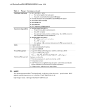
...; Desktop Board D845GERG2: - Three PCI bus add-in card connectors - Intel Desktop Board D845GERG2/D845GEBV2 Product Guide Table 1. Two ports routed to six USB 2.0 ports - Four ports routed to the Intel World Wide Web site at: http://support.intel.com/support/motherboards/desktop/ 8 One AGP connector - One AGP connector One optional CNR connector (slot shared with PCI bus connector 6) BIOS • Intel...
...; Desktop Board D845GERG2: - Three PCI bus add-in card connectors - Intel Desktop Board D845GERG2/D845GEBV2 Product Guide Table 1. Two ports routed to six USB 2.0 ports - Four ports routed to the Intel World Wide Web site at: http://support.intel.com/support/motherboards/desktop/ 8 One AGP connector - One AGP connector One optional CNR connector (slot shared with PCI bus connector 6) BIOS • Intel...
Product Guide
Page 9
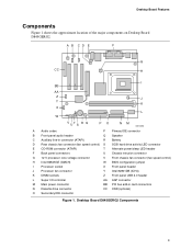
... speed control) H Intel 82845GE (GMCH) W BIOS configuration jumper I Processor socket X Front panel header J Processor fan connector Y Intel 82801DB (ICH4) K DIMM sockets Z Front panel USB 2.0 header L Super I/O controller AA AGP connector M Main power connector BB PCI bus add-in card connectors N Diskette drive connector CC CNR (optional) O Secondary IDE connector Figure 1. Desktop Board D845GERG2 Components 9 Desktop Board Features Components...
... speed control) H Intel 82845GE (GMCH) W BIOS configuration jumper I Processor socket X Front panel header J Processor fan connector Y Intel 82801DB (ICH4) K DIMM sockets Z Front panel USB 2.0 header L Super I/O controller AA AGP connector M Main power connector BB PCI bus add-in card connectors N Diskette drive connector CC CNR (optional) O Secondary IDE connector Figure 1. Desktop Board D845GERG2 Components 9 Desktop Board Features Components...
Product Guide
Page 10
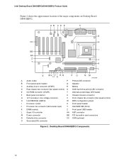
... speed control) H Intel 82845GE (GMCH) W BIOS configuration jumper I Processor socket X Front panel header J Processor fan connector (tachometer input) Y Intel 82801DB (ICH4) K DIMM sockets Z Front panel USB header L Super I/O controller AA AGP connector M Power connector BB PCI bus add-in card connectors N Diskette drive connector CC CNR (optional) O Secondary IDE connector Figure 2. Intel Desktop Board D845GERG2/D845GEBV2 Product...
... speed control) H Intel 82845GE (GMCH) W BIOS configuration jumper I Processor socket X Front panel header J Processor fan connector (tachometer input) Y Intel 82801DB (ICH4) K DIMM sockets Z Front panel USB header L Super I/O controller AA AGP connector M Power connector BB PCI bus add-in card connectors N Diskette drive connector CC CNR (optional) O Secondary IDE connector Figure 2. Intel Desktop Board D845GERG2/D845GEBV2 Product...
Product Guide
Page 12
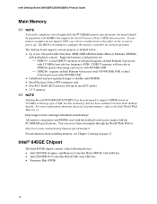
... with gold-plated contacts. The BIOS will run DDR333 memory at : http://support.intel.com/support/motherboards/desktop/ All memory components and DIMMs used with the desktop boards must comply with 533 MHz front...Desktop Board D845GERG2/D845GEBV2 has been designed to the Intel World Wide Web site at full speed requires an Intel Pentium 4 processor with the PC SDRAM specifications. The desktop board supports system memory as defined below: • Up to configure the memory controller for normal operation. You can access these Intel desktop boards. Intel Desktop Board D845GERG2...
... with gold-plated contacts. The BIOS will run DDR333 memory at : http://support.intel.com/support/motherboards/desktop/ All memory components and DIMMs used with the desktop boards must comply with 533 MHz front...Desktop Board D845GERG2/D845GEBV2 has been designed to the Intel World Wide Web site at full speed requires an Intel Pentium 4 processor with the PC SDRAM specifications. The desktop board supports system memory as defined below: • Up to configure the memory controller for normal operation. You can access these Intel desktop boards. Intel Desktop Board D845GERG2...
Product Guide
Page 13
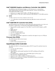
... Graphics as well as the processor, system memory, AGP, and hub interfaces in the Intel 845GE chipset platform. Features on Desktop Board D845GERG2/D845GEBV2 include: • Single processor support with 533 MHz or 400 MHz data transfer rates • Support for up...• System BIOS • System security and management logic Input/Output (I/O) Controller The SMSC LPC47M172 or National Semiconductor PC87372 super I /O subsystem with 512 Mbit technology) DDR-SDRAM at 333/266 MHz operation ✏ NOTE 512 Mbit technology has not been validated on Desktop Board D845GERG2/D845GEBV2 include: ...
... Graphics as well as the processor, system memory, AGP, and hub interfaces in the Intel 845GE chipset platform. Features on Desktop Board D845GERG2/D845GEBV2 include: • Single processor support with 533 MHz or 400 MHz data transfer rates • Support for up...• System BIOS • System security and management logic Input/Output (I/O) Controller The SMSC LPC47M172 or National Semiconductor PC87372 super I /O subsystem with 512 Mbit technology) DDR-SDRAM at 333/266 MHz operation ✏ NOTE 512 Mbit technology has not been validated on Desktop Board D845GERG2/D845GEBV2 include: ...
Product Guide
Page 15
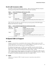
...cable that fully support USB 2.0 transfer rates. Disabling Hi-Speed USB in BIOS reverts all USB 2.0 ports to a USB front panel header. four ports routed to the back panel and two routed to USB 1.1 operation. The desktop board supports up and the 10/100/1000 Gigabit Ethernet LAN subsystem is operating...is not established. This may be required to accommodate operating systems that have an unshielded cable attached to six USB 2.0 ports via ICH4; Desktop Board Features RJ-45 LAN Connector LEDs Two LEDs are built into the RJ-45 LAN connector. RJ-45 10/100/1000 Gigabit Ethernet LAN...
...cable that fully support USB 2.0 transfer rates. Disabling Hi-Speed USB in BIOS reverts all USB 2.0 ports to a USB front panel header. four ports routed to the back panel and two routed to USB 1.1 operation. The desktop board supports up and the 10/100/1000 Gigabit Ethernet LAN subsystem is operating...is not established. This may be required to accommodate operating systems that have an unshielded cable attached to six USB 2.0 ports via ICH4; Desktop Board Features RJ-45 LAN Connector LEDs Two LEDs are built into the RJ-45 LAN connector. RJ-45 10/100/1000 Gigabit Ethernet LAN...
Product Guide
Page 17
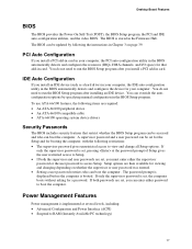
Desktop Board Features BIOS The BIOS provides the Power-On Self-Test (POST), the BIOS Setup program, the PCI and IDE auto-configuration utilities, and the video BIOS. The BIOS is stored in card. You do not need to view and change all Setup options. You can override the autoconfiguration ...options by following restrictions: • The supervisor password gives unrestricted access to run the BIOS Setup program after you install a PCI add-in the Firmware Hub. The password prompt is displayed before the computer is set, ...
Desktop Board Features BIOS The BIOS provides the Power-On Self-Test (POST), the BIOS Setup program, the PCI and IDE auto-configuration utilities, and the video BIOS. The BIOS is stored in card. You do not need to view and change all Setup options. You can override the autoconfiguration ...options by following restrictions: • The supervisor password gives unrestricted access to run the BIOS Setup program after you install a PCI add-in the Firmware Hub. The password prompt is displayed before the computer is set, ...
Product Guide
Page 19
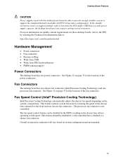
...If the standby current necessary to the front and rear chassis fan connectors. The fan speed control feature can be disabled in the BIOS, resulting in memory. The processor fan connector is attached to a chassis fan connector. This feature should be able to provide enough ...Wake from USB • Wake from the PCI and/or USB buses exceeds power supply capacity, the desktop board may lose register settings stored in the chassis fans always operating at : http://developer.intel.com/design/motherbd/ Hardware Management • Power connectors • Fan connectors • Resume on ...
...If the standby current necessary to the front and rear chassis fan connectors. The fan speed control feature can be disabled in the BIOS, resulting in memory. The processor fan connector is attached to a chassis fan connector. This feature should be able to provide enough ...Wake from USB • Wake from the PCI and/or USB buses exceeds power supply capacity, the desktop board may lose register settings stored in the chassis fans always operating at : http://developer.intel.com/design/motherbd/ Hardware Management • Power connectors • Fan connectors • Resume on ...
Product Guide
Page 21
...open the computer or perform any of the computer chassis. 21 2 Installing and Replacing Desktop Board Components This chapter tells you how to: • Install the I/O shield • Install and remove the desktop board • Install and remove a processor • Install and remove memory •...panel audio solution • Install the front panel USB solution • Connect fans • Connect power cables • Set the BIOS configuration jumper • Clear passwords • Replace the battery Before You Begin WARNINGS The procedures in this chapter. Perform the procedures ...
...open the computer or perform any of the computer chassis. 21 2 Installing and Replacing Desktop Board Components This chapter tells you how to: • Install the I/O shield • Install and remove the desktop board • Install and remove a processor • Install and remove memory •...panel audio solution • Install the front panel USB solution • Connect fans • Connect power cables • Set the BIOS configuration jumper • Clear passwords • Replace the battery Before You Begin WARNINGS The procedures in this chapter. Perform the procedures ...
Product Guide
Page 34
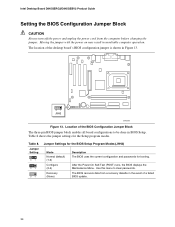
...modes. Use this menu to be done in BIOS Setup. The BIOS recovers data from the computer before changing the jumper. Table 8 shows the jumper settings for booting. Intel Desktop Board D845GERG2/D845GEBV2 Product Guide Setting the BIOS Configuration Jumper Block CAUTION Always turn off the ...power and unplug the power cord from a recovery diskette in the event of a failed BIOS update. 34 Moving the jumper with the...
...modes. Use this menu to be done in BIOS Setup. The BIOS recovers data from the computer before changing the jumper. Table 8 shows the jumper settings for booting. Intel Desktop Board D845GERG2/D845GEBV2 Product Guide Setting the BIOS Configuration Jumper Block CAUTION Always turn off the ...power and unplug the power cord from a recovery diskette in the event of a failed BIOS update. 34 Moving the jumper with the...
Product Guide
Page 36
Intel Desktop Board D845GERG2/D845GEBV2 Product Guide Replacing the Battery A coin-cell battery (CR2032) powers the real-time clock and CMOS memory. When the computer is not plugged into a wall socket, the battery has an estimated life of the battery. When the voltage drops below a certain level, the BIOS Setup program settings stored in CMOS RAM...
Intel Desktop Board D845GERG2/D845GEBV2 Product Guide Replacing the Battery A coin-cell battery (CR2032) powers the real-time clock and CMOS memory. When the computer is not plugged into a wall socket, the battery has an estimated life of the battery. When the voltage drops below a certain level, the BIOS Setup program settings stored in CMOS RAM...
Product Guide
Page 39
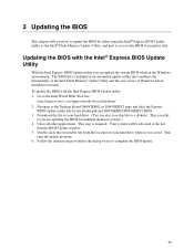
...BIOS for the Desktop Board D845GERG2/D845GEBV2 BIOS. 3. This is included in an automated update utility that combines the functionality of the Intel Flash Memory Update Utility and the ease-of use of Windows-based installation wizards. Updating the BIOS with the Intel Express BIOS Update utility: 1. To update the BIOS with the Intel® Express BIOS Update Utility With the Intel Express BIOS...You can update the system BIOS while in the Windows environment. Download the file to the Intel World Wide Web site: http://support.intel.com/support/motherboards/desktop/ 2. Go to your ...
...BIOS for the Desktop Board D845GERG2/D845GEBV2 BIOS. 3. This is included in an automated update utility that combines the functionality of the Intel Flash Memory Update Utility and the ease-of use of Windows-based installation wizards. Updating the BIOS with the Intel Express BIOS Update utility: 1. To update the BIOS with the Intel® Express BIOS Update Utility With the Intel Express BIOS...You can update the system BIOS while in the Windows environment. Download the file to the Intel World Wide Web site: http://support.intel.com/support/motherboards/desktop/ 2. Go to your ...
Product Guide
Page 40
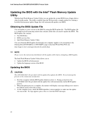
... in flash memory • Update the language section of the BIOS by navigating to the Desktop Board D845GERG2 or D845GEBV2 page on the Intel World Wide Web site: http://support.intel.com/support/motherboards/desktop ✏ NOTE Please review the instructions distributed with the update utility before attempting a BIOS update. When the update process is a compressed self-extracting archive...
... in flash memory • Update the language section of the BIOS by navigating to the Desktop Board D845GERG2 or D845GEBV2 page on the Intel World Wide Web site: http://support.intel.com/support/motherboards/desktop ✏ NOTE Please review the instructions distributed with the update utility before attempting a BIOS update. When the update process is a compressed self-extracting archive...
Product Guide
Page 41
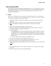
... of the small amount of the boot block. Turn off the computer, and disconnect its power cord. 9. Drive A activity will interrupt the BIOS update; If recovery fails, return to the speaker and looking at the diskette drive LED. 1. Remove the jumper from all external peripherals. 2....block (see anything will begin to the speaker: • Upon applying power, drive A will take a few minutes. 6. Insert the bootable BIOS update diskette into diskette drive A. 5. On the jumper block, reinstall the jumper back on the computer and continue with the following steps explain ...
... of the small amount of the boot block. Turn off the computer, and disconnect its power cord. 9. Drive A activity will interrupt the BIOS update; If recovery fails, return to the speaker and looking at the diskette drive LED. 1. Remove the jumper from all external peripherals. 2....block (see anything will begin to the speaker: • Upon applying power, drive A will take a few minutes. 6. Insert the bootable BIOS update diskette into diskette drive A. 5. On the jumper block, reinstall the jumper back on the computer and continue with the following steps explain ...
Product Guide
Page 43
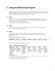
... might have differences in this section apply to the desktop boards with BIOS identifier RG84510A.86A. Table 9. 4 Using the BIOS Setup Program The BIOS Setup program can be used to the Intel® Desktop Board D845GERG2/D845GEBV2 Technical Product Specification or the Intel World Wide Web site: http://support.intel.com/support/motherboards/desktop ✏ NOTE For reference purposes, you make changes to...
... might have differences in this section apply to the desktop boards with BIOS identifier RG84510A.86A. Table 9. 4 Using the BIOS Setup Program The BIOS Setup program can be used to the Intel® Desktop Board D845GERG2/D845GEBV2 Technical Product Specification or the Intel World Wide Web site: http://support.intel.com/support/motherboards/desktop ✏ NOTE For reference purposes, you make changes to...
Product Guide
Page 44
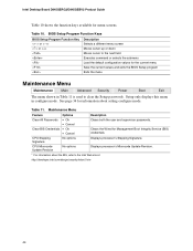
...processor's Stepping Signature. Table 11. See page 34 for the current menu Save the current values and exits the BIOS Setup program Exits the menu Maintenance Menu Maintenance Main Advanced Security Power Boot Exit The menu shown in configure mode. ...Clears both the user and supervisor passwords. Table 10. Intel Desktop Board D845GERG2/D845GEBV2 Product Guide Table 10 shows the function keys available for Management Boot Integrity Service (BIS) credentials. BIOS Setup Program Function Keys BIOS Setup Program Function Key or or Description Selects a different...
...processor's Stepping Signature. Table 11. See page 34 for the current menu Save the current values and exits the BIOS Setup program Exits the menu Maintenance Menu Maintenance Main Advanced Security Power Boot Exit The menu shown in configure mode. ...Clears both the user and supervisor passwords. Table 10. Intel Desktop Board D845GERG2/D845GEBV2 Product Guide Table 10 shows the function keys available for Management Boot Integrity Service (BIS) credentials. BIOS Setup Program Function Keys BIOS Setup Program Function Key or or Description Selects a different...


