

Product Guide
Page 4
Intel Desktop Boards D845EPT2 and D845EBG2 Product Guide Installing and Removing a Processor 24 Installing a Processor 24 Installing the Processor Fan Heat Sink 24 Connecting the Processor Fan Heat Sink ... 28 Setting the BIOS Configuration Jumper Block 30 Installing the Front Panel Audio Solution 31 Clearing Passwords...32 Replacing the Battery ...33 3 Updating the BIOS Updating the BIOS with the Intel® Express BIOS Update Utility 37 Updating the BIOS with the Intel® Flash Memory Update Utility 38 Obtaining the BIOS Update...
Intel Desktop Boards D845EPT2 and D845EBG2 Product Guide Installing and Removing a Processor 24 Installing a Processor 24 Installing the Processor Fan Heat Sink 24 Connecting the Processor Fan Heat Sink ... 28 Setting the BIOS Configuration Jumper Block 30 Installing the Front Panel Audio Solution 31 Clearing Passwords...32 Replacing the Battery ...33 3 Updating the BIOS Updating the BIOS with the Intel® Express BIOS Update Utility 37 Updating the BIOS with the Intel® Flash Memory Update Utility 38 Obtaining the BIOS Update...

Product Guide
Page 5
... and Peripheral Interface Connectors 65 17. Connecting the IDE Cable 29 11. Back Panel Connectors 62 14. Installing the I/O Shield 22 5. Desktop Board D845EPT2 Add-in Card and Peripheral Interface Connectors .......... 66 18. Contents 5 Technical Reference Connectors...61 Back Panel Connectors 62 Midboard Connectors 63 Audio Connectors 63 Power and Hardware Connectors 64...
... and Peripheral Interface Connectors 65 17. Connecting the IDE Cable 29 11. Back Panel Connectors 62 14. Installing the I/O Shield 22 5. Desktop Board D845EPT2 Add-in Card and Peripheral Interface Connectors .......... 66 18. Contents 5 Technical Reference Connectors...61 Back Panel Connectors 62 Midboard Connectors 63 Audio Connectors 63 Power and Hardware Connectors 64...
Product Guide
Page 6
... Submenu ...56 23. Safety Regulations...75 37. Intel Desktop Boards D845EPT2 and D845EBG2 Product Guide Tables 1. Jumper Settings for the BIOS Setup Program Modes (J8H2 30 5. PCI Configuration Submenu 46 12. Boot Configuration Submenu 47 13. Front Panel USB 2.0 Header (J9F1 67 31. System Memory...Peripheral Configuration Submenu 48 14. Beep Codes...71 35. Front Panel Audio Header Signal Names (J8B1 63 30. DMA Channels...68 33. Hard Disk Drives Submenu 59 26. Processors Supported by the Desktop Boards D845EPT2 and D845EBG2 11 3. BIOS Setup Program Menu Bar 41 ...
... Submenu ...56 23. Safety Regulations...75 37. Intel Desktop Boards D845EPT2 and D845EBG2 Product Guide Tables 1. Jumper Settings for the BIOS Setup Program Modes (J8H2 30 5. PCI Configuration Submenu 46 12. Boot Configuration Submenu 47 13. Front Panel USB 2.0 Header (J9F1 67 31. System Memory...Peripheral Configuration Submenu 48 14. Beep Codes...71 35. Front Panel Audio Header Signal Names (J8B1 63 30. DMA Channels...68 33. Hard Disk Drives Submenu 59 26. Processors Supported by the Desktop Boards D845EPT2 and D845EBG2 11 3. BIOS Setup Program Menu Bar 41 ...
Product Guide
Page 7
...2 GB, but this technology has not been validated on 512 Mbit technology up to the back panel - 1 Desktop Board Features ✏ NOTE The Intel® Desktop Board D845EPT2 layout was used for a single Intel® Pentium® 4 processor with 533/400 MHz front side bus (FSB) frequency in an... GB of system memory Chipset I/O Control Graphics Audio LAN (optional) Peripheral Interfaces NOTE: The Desktop Boards D845EPT2 and D845EBG2 have been designed to support DIMMs based on these Intel® desktop boards. For more information about the latest list of tested memory, refer to six Hi-...
...2 GB, but this technology has not been validated on 512 Mbit technology up to the back panel - 1 Desktop Board Features ✏ NOTE The Intel® Desktop Board D845EPT2 layout was used for a single Intel® Pentium® 4 processor with 533/400 MHz front side bus (FSB) frequency in an... GB of system memory Chipset I/O Control Graphics Audio LAN (optional) Peripheral Interfaces NOTE: The Desktop Boards D845EPT2 and D845EBG2 have been designed to support DIMMs based on these Intel® desktop boards. For more information about the latest list of tested memory, refer to six Hi-...

Product Guide
Page 9
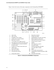
... connector Q Firmware Hub (FWH) C CD-ROM connector (ATAPI) R Intel 82801DB I/O Controller Hub (ICH4) D Auxiliary line-in connector (ATAPI) S BIOS configuration jumper block E Back panel connectors T SCSI hard drive activity LED connector F 12 V processor core...Intel 82845E Memory Controller Hub (MCH) W Front chassis fan connector I Processor socket X Front panel header J Processor fan connector (tachometer input) Y Alternate power/sleep LED header K DIMM sockets Z Front panel... Primary IDE connector DD Front panel audio header Figure 1. Desktop Board Features Desktop Board Components ...
... connector Q Firmware Hub (FWH) C CD-ROM connector (ATAPI) R Intel 82801DB I/O Controller Hub (ICH4) D Auxiliary line-in connector (ATAPI) S BIOS configuration jumper block E Back panel connectors T SCSI hard drive activity LED connector F 12 V processor core...Intel 82845E Memory Controller Hub (MCH) W Front chassis fan connector I Processor socket X Front panel header J Processor fan connector (tachometer input) Y Alternate power/sleep LED header K DIMM sockets Z Front panel... Primary IDE connector DD Front panel audio header Figure 1. Desktop Board Features Desktop Board Components ...
Product Guide
Page 10
... A Audio codec P Floppy drive connector B AGP connector Q Firmware Hub (FWH) C CD-ROM connector (ATAPI) R Intel 82801DB I/O Controller Hub (ICH4) D Auxiliary line-in connector (ATAPI) S BIOS configuration jumper block E Back panel connectors T SCSI hard drive activity LED connector F 12 V processor core voltage connector U Chassis intrusion connector G Rear chassis...Networking Riser (CNR) (optional) O Primary IDE connector DD Front panel audio header Figure 2. Intel Desktop Boards D845EPT2 and D845EBG2 Product Guide Figure 2 shows the location of the major components on the ...
... A Audio codec P Floppy drive connector B AGP connector Q Firmware Hub (FWH) C CD-ROM connector (ATAPI) R Intel 82801DB I/O Controller Hub (ICH4) D Auxiliary line-in connector (ATAPI) S BIOS configuration jumper block E Back panel connectors T SCSI hard drive activity LED connector F 12 V processor core voltage connector U Chassis intrusion connector G Rear chassis...Networking Riser (CNR) (optional) O Primary IDE connector DD Front panel audio header Figure 2. Intel Desktop Boards D845EPT2 and D845EBG2 Product Guide Figure 2 shows the location of the major components on the ...

Product Guide
Page 14
... audio quality may occur if passive (non-amplified) speakers are connected to power either headphones or amplified speakers only. Intel Desktop Boards D845EPT2 and D845EBG2 Product Guide Audio Subsystem The audio subsystem features the following functions: • Basic 10/100 Ethernet LAN ...LEDs Two LEDs are available from Intel's customer support World Wide Web site: http://support.intel.com/support/motherboards/desktop/ LAN Subsystem (Optional) The optional Intel 82562ET (with another computer on the back panel, is communicating with the Intel 82801DB ICH4) provides a Fast PCI...
... audio quality may occur if passive (non-amplified) speakers are connected to power either headphones or amplified speakers only. Intel Desktop Boards D845EPT2 and D845EBG2 Product Guide Audio Subsystem The audio subsystem features the following functions: • Basic 10/100 Ethernet LAN ...LEDs Two LEDs are available from Intel's customer support World Wide Web site: http://support.intel.com/support/motherboards/desktop/ LAN Subsystem (Optional) The optional Intel 82562ET (with another computer on the back panel, is communicating with the Intel 82801DB ICH4) provides a Fast PCI...

Product Guide
Page 15
... do not support USB 2.0. ✏ NOTE USB devices are backward compatible with USB 1.1 devices. four ports routed to the back panel and two routed to operating system and driver initialization. These Intel desktop boards support up to USB 1.1 operation. USB 2.0 support requires both an operating system and drivers that meets the requirements...-33 and ATA-66/100 protocols • Laser servo (LS-120) drives 15 USB 2.0 ports are limited to USB 1.1 transfer rates prior to a USB front panel header.
... do not support USB 2.0. ✏ NOTE USB devices are backward compatible with USB 1.1 devices. four ports routed to the back panel and two routed to operating system and driver initialization. These Intel desktop boards support up to USB 1.1 operation. USB 2.0 support requires both an operating system and drivers that meets the requirements...-33 and ATA-66/100 protocols • Laser servo (LS-120) drives 15 USB 2.0 ports are limited to USB 1.1 transfer rates prior to a USB front panel header.

Product Guide
Page 18
Intel Desktop Boards D845EPT2 and D845EBG2 Product Guide Instantly Available PC technology enables the board to enter the ... state) configuration. If the standby current necessary to its last known awake state. For more information on the front panel, the sleep state is standby power to the TPS by the LED turning amber. If the system has a dual...returns to support multiple wake events from the PCI and/or USB buses exceeds power supply capacity, the Intel desktop board may lose register settings stored in Figure 3, is lit when there is indicated by selecting the Technical Documentation...
Intel Desktop Boards D845EPT2 and D845EBG2 Product Guide Instantly Available PC technology enables the board to enter the ... state) configuration. If the standby current necessary to its last known awake state. For more information on the front panel, the sleep state is standby power to the TPS by the LED turning amber. If the system has a dual...returns to support multiple wake events from the PCI and/or USB buses exceeds power supply capacity, the Intel desktop board may lose register settings stored in Figure 3, is lit when there is indicated by selecting the Technical Documentation...

Product Guide
Page 21
...memory • Install and remove an AGP card • Connect the IDE cable • Set the BIOS jumper • Install the front panel audio solution • Clear passwords • Replace the battery Before You Begin CAUTION Before you install this chapter only at an ESD workstation using... electronic equipment. Perform the procedures described in this board in personal injury or equipment damage. Failure to operate even though the front panel power button is not available, you can provide some ESD protection by wearing an antistatic wrist strap and attaching it to record information...
...memory • Install and remove an AGP card • Connect the IDE cable • Set the BIOS jumper • Install the front panel audio solution • Clear passwords • Replace the battery Before You Begin CAUTION Before you install this chapter only at an ESD workstation using... electronic equipment. Perform the procedures described in this board in personal injury or equipment damage. Failure to operate even though the front panel power button is not available, you can provide some ESD protection by wearing an antistatic wrist strap and attaching it to record information...

Product Guide
Page 27
... card's metal bracket to the computer. Installing and Replacing Desktop Board Components 5. Remove the AC power cord from its anti-static package. 7. The Desktop Boards D845EPT2 and D845EBG2 have an integrated AGP retention mechanism (RM). Make sure the clips are pushed outward to reach the DIMM sockets. 10. Reinstall the AGP... clips at each end of the DIMM socket(s) are firmly in an anti-static package. 8. Turn off all peripheral devices connected to the chassis back panel with a screw. 27 Turn off the computer. 3.
... card's metal bracket to the computer. Installing and Replacing Desktop Board Components 5. Remove the AC power cord from its anti-static package. 7. The Desktop Boards D845EPT2 and D845EBG2 have an integrated AGP retention mechanism (RM). Make sure the clips are pushed outward to reach the DIMM sockets. 10. Reinstall the AGP... clips at each end of the DIMM socket(s) are firmly in an anti-static package. 8. Turn off all peripheral devices connected to the chassis back panel with a screw. 27 Turn off the computer. 3.

Product Guide
Page 28
... B E A C D Figure 9. Removing the AGP Card OM10595 Connecting the IDE Cable The Intel® boxed desktop board package includes an IDE cable. The cable connects two drives to the chassis back panel. 2. Figure 10 shows the correct installation of the slowest drive. 28 The cable supports the Ultra...the same cable, the maximum transfer rate between the drives may be reduced to remove the AGP card from the RM: 1. Intel Desktop Boards D845EPT2 and D845EBG2 Product Guide Removing the AGP Card Follow these instructions to that secures the card's metal bracket (A) to the desktop ...
... B E A C D Figure 9. Removing the AGP Card OM10595 Connecting the IDE Cable The Intel® boxed desktop board package includes an IDE cable. The cable connects two drives to the chassis back panel. 2. Figure 10 shows the correct installation of the slowest drive. 28 The cable supports the Ultra...the same cable, the maximum transfer rate between the drives may be reduced to remove the AGP card from the RM: 1. Intel Desktop Boards D845EPT2 and D845EBG2 Product Guide Removing the AGP Card Follow these instructions to that secures the card's metal bracket (A) to the desktop ...

Product Guide
Page 31
...disconnect the AC power cord. 3. Installing and Replacing Desktop Board Components Installing the Front Panel Audio Solution To install the cable that connects the front panel audio solution to the front panel audio header, follow these steps: 1. Observe the precautions in "Before You Begin"... steps: 1. Remove the cover. 4. Install a jumper on page 63. 5. Connect the audio cable to disable the back panel audio connectors. 6. Replace the cover. 31 Locate the front panel audio header (J8B1), see Figure 14 on pins 5-6 (rear R channel). 6. Remove the cover. 4. Install a jumper...
...disconnect the AC power cord. 3. Installing and Replacing Desktop Board Components Installing the Front Panel Audio Solution To install the cable that connects the front panel audio solution to the front panel audio header, follow these steps: 1. Observe the precautions in "Before You Begin"... steps: 1. Remove the cover. 4. Install a jumper on page 63. 5. Connect the audio cable to disable the back panel audio connectors. 6. Replace the cover. 31 Locate the front panel audio header (J8B1), see Figure 14 on pins 5-6 (rear R channel). 6. Remove the cover. 4. Install a jumper...

Product Guide
Page 61
...) to the computer chassis. Audio connectors - A fault in board and peripheral interface connectors • Front panel headers CAUTION Many of the midboard and front panel connectors provide operating voltage (+5 V dc and +12 V dc, for powering devices external to devices inside the... computer chassis, such as fans and internal peripherals. Power and hardware connectors - 5 Technical Reference Connectors The Intel desktop board connectors can ...
...) to the computer chassis. Audio connectors - A fault in board and peripheral interface connectors • Front panel headers CAUTION Many of the midboard and front panel connectors provide operating voltage (+5 V dc and +12 V dc, for powering devices external to devices inside the... computer chassis, such as fans and internal peripherals. Power and hardware connectors - 5 Technical Reference Connectors The Intel desktop board connectors can ...

Product Guide
Page 62
... ✏ NOTE The line out connector, located on the back panel, is designed to this output. 62 Poor audio quality may occur if passive (non-amplified) speakers are connected to power either headphones or amplified speakers ... in Audio line out Audio line in Color Green Purple Black Black Burgundy Teal Black Black Black Pink Lime green Light blue OM13662 Figure 13. Intel Desktop Boards D845EPT2 and D845EBG2 Product Guide Back Panel Connectors Figure 13 shows the back...
... ✏ NOTE The line out connector, located on the back panel, is designed to this output. 62 Poor audio quality may occur if passive (non-amplified) speakers are connected to power either headphones or amplified speakers ... in Audio line out Audio line in Color Green Purple Black Black Burgundy Teal Black Black Black Pink Lime green Light blue OM13662 Figure 13. Intel Desktop Boards D845EPT2 and D845EBG2 Product Guide Back Panel Connectors Figure 13 shows the back...

Product Guide
Page 63
Front Panel Audio Header Signal Names (J8B1) Pin Signal Name 1 AUD-MIC 3 AUD-MIC-BIAS 5 AUD-FPOUT-R 7 HP-ON 9 AUD-FPOUT-L Pin Signal Name 2 AUD-GND 4 AUD-... connectors. Audio Connectors Table 29 shows the pin assignments for pin assignments) Auxiliary line in CD-ROM Figure 14. B C 1 2 3 4 A 5 6 7 9 10 1 4 4 1 Technical Reference Item A B C Description Front panel audio (see Table 29 for the front...
Front Panel Audio Header Signal Names (J8B1) Pin Signal Name 1 AUD-MIC 3 AUD-MIC-BIAS 5 AUD-FPOUT-R 7 HP-ON 9 AUD-FPOUT-L Pin Signal Name 2 AUD-GND 4 AUD-... connectors. Audio Connectors Table 29 shows the pin assignments for pin assignments) Auxiliary line in CD-ROM Figure 14. B C 1 2 3 4 A 5 6 7 9 10 1 4 4 1 Technical Reference Item A B C Description Front panel audio (see Table 29 for the front...

Product Guide
Page 67
... Figure 18 shows the location of the front panel headers. 1 2 3 4 A 5 6 7 10 Technical Reference 8 C 6 4 2 1 2 3 4 B5 6 7 8 10 9 7 5 3 1 Item A B C D D OM13658 Description Front panel audio (see Table 29 on page 63 for pin assignments) Front panel USB 2.0 (see Table 30 for the front panel USB 2.0 header. Front Panel USB 2.0 Header (J9F1) Pin Signal name Pin 1 VREG_FP_WSBPWR0 2 3 USB_FPP0- 4 5 USB_FPP0+ 6 7 Ground...
... Figure 18 shows the location of the front panel headers. 1 2 3 4 A 5 6 7 10 Technical Reference 8 C 6 4 2 1 2 3 4 B5 6 7 8 10 9 7 5 3 1 Item A B C D D OM13658 Description Front panel audio (see Table 29 on page 63 for pin assignments) Front panel USB 2.0 (see Table 30 for the front panel USB 2.0 header. Front Panel USB 2.0 Header (J9F1) Pin Signal name Pin 1 VREG_FP_WSBPWR0 2 3 USB_FPP0- 4 5 USB_FPP0+ 6 7 Ground...

D845EPT2_D845EBG2_TechProdSpec.
Page 6
Intel Desktop Board D845EBG2/D845EPT2 Technical Product Specification 2 Technical Reference 2.1 Introduction...47 2.2 Memory Map ...47 2.3 Fixed I/O Map...48 2.4 DMA Channels ...49 2.5 PCI Configuration Space Map 49 2.6 Interrupts ...50 2.7 PCI Interrupt Routing Map 51 2.8 Connectors ...53 2.8.1 Back Panel Connectors 54 2.8.2 Internal I/O Connectors 57 2.8.3 External I/O Connectors 70 2.9 Jumper Blocks...74 2.9.1 Front Panel Audio Connector/Jumper Block 74...
Intel Desktop Board D845EBG2/D845EPT2 Technical Product Specification 2 Technical Reference 2.1 Introduction...47 2.2 Memory Map ...47 2.3 Fixed I/O Map...48 2.4 DMA Channels ...49 2.5 PCI Configuration Space Map 49 2.6 Interrupts ...50 2.7 PCI Interrupt Routing Map 51 2.8 Connectors ...53 2.8.1 Back Panel Connectors 54 2.8.2 Internal I/O Connectors 57 2.8.3 External I/O Connectors 70 2.9 Jumper Blocks...74 2.9.1 Front Panel Audio Connector/Jumper Block 74...
D845EPT2_D845EBG2_TechProdSpec.
Page 8
...Mouse/Keyboard Connector 55 19. Auxiliary Line In Connector 59 27. Processor Fan Connector 61 31. Back Panel Connectors 54 11. External I /O Map ...48 14. Desktop Board D845EPT2 Dimensions 77 19. Summary of the Jumper Blocks 74 17. Audio Line In Connector (Optional 56 ...of the Standby Power Indicator LED 44 10. Desktop Board D845EBG2 Dimensions 76 18. Power States and Targeted System Power 39 9. Intel Desktop Board D845EBG2/D845EPT2 Technical Product Specification 9. I /O Shield Dimensions (for Desktop Boards with no LAN Subsystem 79 21. Audio Line Out Connector ...
...Mouse/Keyboard Connector 55 19. Auxiliary Line In Connector 59 27. Processor Fan Connector 61 31. Back Panel Connectors 54 11. External I /O Map ...48 14. Desktop Board D845EPT2 Dimensions 77 19. Summary of the Jumper Blocks 74 17. Audio Line In Connector (Optional 56 ...of the Standby Power Indicator LED 44 10. Desktop Board D845EBG2 Dimensions 76 18. Power States and Targeted System Power 39 9. Intel Desktop Board D845EBG2/D845EPT2 Technical Product Specification 9. I /O Shield Dimensions (for Desktop Boards with no LAN Subsystem 79 21. Audio Line Out Connector ...

D845EPT2_D845EBG2_TechProdSpec.
Page 9
... 111 71. Power Menu ...114 74. ACPI Submenu...114 75. ATAPI CD-ROM Drives Submenu 118 ix Front Panel USB Connector 71 43. Front Panel Audio Connector/Jumper Block 75 48. Supervisor and User Password Functions 96 57. Main Menu...99 61. IDE Configuration... 112 72. Boot Menu ...115 76. Diskette Configuration Submenu 108 68. Front Chassis Fan Connector 62 33. Front Panel Connector 72 45. Desktop Board D845EBG2/D845EPT2 Environmental Specifications 85 54. Chassis Intrusion Connector 62 34. SCSI LED Connector 69 40. Serial Port B Connector 71 ...
... 111 71. Power Menu ...114 74. ACPI Submenu...114 75. ATAPI CD-ROM Drives Submenu 118 ix Front Panel USB Connector 71 43. Front Panel Audio Connector/Jumper Block 75 48. Supervisor and User Password Functions 96 57. Main Menu...99 61. IDE Configuration... 112 72. Boot Menu ...115 76. Diskette Configuration Submenu 108 68. Front Chassis Fan Connector 62 33. Front Panel Connector 72 45. Desktop Board D845EBG2/D845EPT2 Environmental Specifications 85 54. Chassis Intrusion Connector 62 34. SCSI LED Connector 69 40. Serial Port B Connector 71 ...


