Product Guide
Page 3
Contents 1 Desktop Board Features Desktop Board Components 9 Processor ...11 Main Memory ...12 Intel® 845E Chipset ...12 Intel® 82845E Memory Controller Hub (MCH 13 Intel® 82801DB I/O Controller Hub (ICH4 13 Firmware Hub (FWH 13 Input/Output (I/O) Controller 13 Audio Subsystem ...14...Support 15 Enhanced IDE Interface ...15 Expansion Slots...16 Accelerated Graphics Port (AGP 16 Communication and Networking Riser (CNR) (Optional 16 BIOS ...16 PCI Auto Configuration 16 IDE Auto Configuration 17 Security Passwords 17 Power Management Features 17 ACPI ...17 Suspend to RAM (...
Contents 1 Desktop Board Features Desktop Board Components 9 Processor ...11 Main Memory ...12 Intel® 845E Chipset ...12 Intel® 82845E Memory Controller Hub (MCH 13 Intel® 82801DB I/O Controller Hub (ICH4 13 Firmware Hub (FWH 13 Input/Output (I/O) Controller 13 Audio Subsystem ...14...Support 15 Enhanced IDE Interface ...15 Expansion Slots...16 Accelerated Graphics Port (AGP 16 Communication and Networking Riser (CNR) (Optional 16 BIOS ...16 PCI Auto Configuration 16 IDE Auto Configuration 17 Security Passwords 17 Power Management Features 17 ACPI ...17 Suspend to RAM (...

Product Guide
Page 4
Intel Desktop Boards D845EPT2 and D845EBG2 Product Guide Installing and Removing a Processor 24 Installing a Processor 24 Installing the Processor Fan Heat Sink 24 Connecting the Processor Fan Heat Sink Cable 25 ... Clearing Passwords...32 Replacing the Battery ...33 3 Updating the BIOS Updating the BIOS with the Intel® Express BIOS Update Utility 37 Updating the BIOS with the Intel® Flash Memory Update Utility 38 Obtaining the BIOS Update File 38 Updating the BIOS...38 Recovering the BIOS 39 4 Using the BIOS Setup Program Maintenance Menu...42 Extended Configuration Submenu 43...
Intel Desktop Boards D845EPT2 and D845EBG2 Product Guide Installing and Removing a Processor 24 Installing a Processor 24 Installing the Processor Fan Heat Sink 24 Connecting the Processor Fan Heat Sink Cable 25 ... Clearing Passwords...32 Replacing the Battery ...33 3 Updating the BIOS Updating the BIOS with the Intel® Express BIOS Update Utility 37 Updating the BIOS with the Intel® Flash Memory Update Utility 38 Obtaining the BIOS Update File 38 Updating the BIOS...38 Recovering the BIOS 39 4 Using the BIOS Setup Program Maintenance Menu...42 Extended Configuration Submenu 43...

Product Guide
Page 5
... Processor Fan Heat Sink Cable to the Processor Fan Connector..... 25 8. Installing the I/O Shield 22 5. Desktop Board D845EBG2 Mounting Holes 23 6. Desktop Board D845EBG2 Components 10 3. Desktop Board D845EPT2 Add-in Card and Peripheral Interface Connectors .......... 66 18. Desktop Board D845EPT2 Components 9 2. Location of the BIOS Configuration Jumper Block 30 12. Installing a Processor 24 7. Removing the AGP Card 28 10. Audio...
... Processor Fan Heat Sink Cable to the Processor Fan Connector..... 25 8. Installing the I/O Shield 22 5. Desktop Board D845EBG2 Mounting Holes 23 6. Desktop Board D845EBG2 Components 10 3. Desktop Board D845EPT2 Add-in Card and Peripheral Interface Connectors .......... 66 18. Desktop Board D845EPT2 Components 9 2. Location of the BIOS Configuration Jumper Block 30 12. Installing a Processor 24 7. Removing the AGP Card 28 10. Audio...
Product Guide
Page 6
... Regulations...75 37. Extended Configuration Submenu 43 9. IDE Configuration Submenu 50 15. Processors Supported by the Desktop Boards D845EPT2 and D845EBG2 11 3. BIOS Setup Program Function Keys 42 7. Main Menu...44 10. USB Configuration Submenu 55 20. Removable Devices Submenu... EMC Regulations...75 vi Feature Summary ...7 2. BIOS Setup Program Menu Bar 41 6. Jumper Settings for the BIOS Setup Program Modes (J8H2 30 5. Power Menu ...56 22. Hard Disk Drives Submenu 59 26. Intel Desktop Boards D845EPT2 and D845EBG2 Product Guide Tables 1. Maintenance Menu ...42 ...
... Regulations...75 37. Extended Configuration Submenu 43 9. IDE Configuration Submenu 50 15. Processors Supported by the Desktop Boards D845EPT2 and D845EBG2 11 3. BIOS Setup Program Function Keys 42 7. Main Menu...44 10. USB Configuration Submenu 55 20. Removable Devices Submenu... EMC Regulations...75 vi Feature Summary ...7 2. BIOS Setup Program Menu Bar 41 6. Jumper Settings for the BIOS Setup Program Modes (J8H2 30 5. Power Menu ...56 22. Hard Disk Drives Submenu 59 26. Intel Desktop Boards D845EPT2 and D845EBG2 Product Guide Tables 1. Maintenance Menu ...42 ...

Product Guide
Page 8
... For information about Intel Desktop Boards D845EPT2 and D845EBG2, including the Technical Product Specification (TPS), BIOS updates, and device drivers, go to the Intel customer support World Wide Web site: http://support.intel.com/support/motherboards/desktop/ 8 One optional CNR connector (slot shared with PCI bus connector 6) BIOS • Intel/AMI BIOS • Intel® Rapid BIOS Boot • Intel® Express BIOS Update • SMBIOS...
... For information about Intel Desktop Boards D845EPT2 and D845EBG2, including the Technical Product Specification (TPS), BIOS updates, and device drivers, go to the Intel customer support World Wide Web site: http://support.intel.com/support/motherboards/desktop/ 8 One optional CNR connector (slot shared with PCI bus connector 6) BIOS • Intel/AMI BIOS • Intel® Rapid BIOS Boot • Intel® Express BIOS Update • SMBIOS...

Product Guide
Page 9
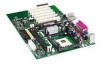
... P ON M OM13673 A Audio codec P Floppy drive connector B AGP connector Q Firmware Hub (FWH) C CD-ROM connector (ATAPI) R Intel 82801DB I/O Controller Hub (ICH4) D Auxiliary line-in connector (ATAPI) S BIOS configuration jumper block E Back panel connectors T SCSI hard drive activity LED connector F 12 V processor core voltage connector U Chassis intrusion connector G Rear... O Primary IDE connector DD Front panel audio header Figure 1. Desktop Board D845EPT2 Components 9 Desktop Board Features Desktop Board Components Figure 1 shows the location of the major components on the...
... P ON M OM13673 A Audio codec P Floppy drive connector B AGP connector Q Firmware Hub (FWH) C CD-ROM connector (ATAPI) R Intel 82801DB I/O Controller Hub (ICH4) D Auxiliary line-in connector (ATAPI) S BIOS configuration jumper block E Back panel connectors T SCSI hard drive activity LED connector F 12 V processor core voltage connector U Chassis intrusion connector G Rear... O Primary IDE connector DD Front panel audio header Figure 1. Desktop Board D845EPT2 Components 9 Desktop Board Features Desktop Board Components Figure 1 shows the location of the major components on the...
Product Guide
Page 10
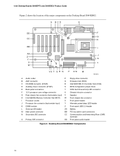
Desktop Board D845EBG2 Components 10 Intel Desktop Boards D845EPT2 and D845EBG2 Product Guide Figure 2 shows the location of the major components on the Desktop Board D845EBG2. A BCD E DD F G CC H BB I AA J Z Y K X L W VU T S R Q P O N M OM13672 A Audio codec P Floppy drive connector B AGP connector Q Firmware Hub (FWH) C CD-ROM connector (ATAPI) R Intel 82801DB I/O Controller Hub (ICH4) D Auxiliary line-in connector (ATAPI) S BIOS configuration jumper block E Back panel...
Desktop Board D845EBG2 Components 10 Intel Desktop Boards D845EPT2 and D845EBG2 Product Guide Figure 2 shows the location of the major components on the Desktop Board D845EBG2. A BCD E DD F G CC H BB I AA J Z Y K X L W VU T S R Q P O N M OM13672 A Audio codec P Floppy drive connector B AGP connector Q Firmware Hub (FWH) C CD-ROM connector (ATAPI) R Intel 82801DB I/O Controller Hub (ICH4) D Auxiliary line-in connector (ATAPI) S BIOS configuration jumper block E Back panel...

Product Guide
Page 12
...BIOS will see Chapter 2 starting on the screen at power up to this technology has not been validated on these documents through the Internet at : http://support.intel.com/support/motherboards/desktop/ All memory components and DIMMs used with the Intel desktop boards must comply with AHA bus • Firmware Hub (FWH) 12 You can access these Intel desktop boards... Mbit technology) ✏ NOTE The Desktop Boards D845EPT2 and D845EBG2 have been designed to support DIMMs based on 512 Mbit technology up . Intel Desktop Boards D845EPT2 and D845EBG2 Product Guide Main Memory ✏ NOTE...
...BIOS will see Chapter 2 starting on the screen at power up to this technology has not been validated on these documents through the Internet at : http://support.intel.com/support/motherboards/desktop/ All memory components and DIMMs used with the Intel desktop boards must comply with AHA bus • Firmware Hub (FWH) 12 You can access these Intel desktop boards... Mbit technology) ✏ NOTE The Desktop Boards D845EPT2 and D845EBG2 have been designed to support DIMMs based on 512 Mbit technology up . Intel Desktop Boards D845EPT2 and D845EBG2 Product Guide Main Memory ✏ NOTE...

Product Guide
Page 13
...• System BIOS • System security and management logic Input/Output (I/O) Controller The SMSC LPC47M102S ultra I/O controller features the following: • Low pin count (LPC) interface • Two serial ports (one via an Intel desktop board header) •...; One parallel port with Extended Capabilities Port (ECP) and Enhanced Parallel Port (EPP) support • Serial IRQ interface compatible with 512 Mbit technology) DDR SDRAM at 266/200 MHz operation ✏ NOTE 512 Mbit technology has not been validated on Desktop Boards D845EPT2 and D845EBG2...
...• System BIOS • System security and management logic Input/Output (I/O) Controller The SMSC LPC47M102S ultra I/O controller features the following: • Low pin count (LPC) interface • Two serial ports (one via an Intel desktop board header) •...; One parallel port with Extended Capabilities Port (ECP) and Enhanced Parallel Port (EPP) support • Serial IRQ interface compatible with 512 Mbit technology) DDR SDRAM at 266/200 MHz operation ✏ NOTE 512 Mbit technology has not been validated on Desktop Boards D845EPT2 and D845EBG2...

Product Guide
Page 15
... Zip† drives inside the computer. four ports routed to the back panel and two routed to the cable. Disabling Hi-Speed USB in BIOS reverts all USB 2.0 ports to operating system and driver initialization. USB 2.0 ports are limited to USB 1.1 transfer rates prior to USB 1.1 operation... and drivers that meets the requirements for a full-speed USB device. The interface supports: • Up to six USB 2.0 ports via ICH4; These Intel desktop boards support up to four IDE devices (such as hard drives) • ATAPI devices (such as CD-ROM drives) • Older PIO Mode devices &#...
... Zip† drives inside the computer. four ports routed to the back panel and two routed to the cable. Disabling Hi-Speed USB in BIOS reverts all USB 2.0 ports to operating system and driver initialization. USB 2.0 ports are limited to USB 1.1 transfer rates prior to USB 1.1 operation... and drivers that meets the requirements for a full-speed USB device. The interface supports: • Up to six USB 2.0 ports via ICH4; These Intel desktop boards support up to four IDE devices (such as hard drives) • ATAPI devices (such as CD-ROM drives) • Older PIO Mode devices &#...

Product Guide
Page 16
...; One optional CNR connector (slot shared with PCI bus connector 3) The Desktop Board D845EBG2 has: • Six PCI bus add-in card connectors • SMBus routed to run the BIOS Setup program after you install a PCI add-in card in your computer,...AGP) ✏ NOTE The Desktop Boards D845EPT2 and D845EBG2 are only compatible with 1.5 V AGP cards. The BIOS is intended for graphics-intensive applications, such as audio, modem, and LAN. Intel Desktop Boards D845EPT2 and D845EBG2 Product Guide Expansion Slots The Desktop Boards D845EPT2 and D845EBG2 have the following the instructions...
...; One optional CNR connector (slot shared with PCI bus connector 3) The Desktop Board D845EBG2 has: • Six PCI bus add-in card connectors • SMBus routed to run the BIOS Setup program after you install a PCI add-in card in your computer,...AGP) ✏ NOTE The Desktop Boards D845EPT2 and D845EBG2 are only compatible with 1.5 V AGP cards. The BIOS is intended for graphics-intensive applications, such as audio, modem, and LAN. Intel Desktop Boards D845EPT2 and D845EBG2 Product Guide Expansion Slots The Desktop Boards D845EPT2 and D845EBG2 have the following the instructions...
Product Guide
Page 17
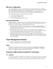
...password and a user password can be set for the Setup and for booting the computer, with the Desktop Board D845EPT2 or D845EBG2 requires an operating system that restrict whether the BIOS Setup program can be capable of ACPI with the following items are then available for the power supply must... program. Power Management Features • Advanced Configuration and Power Interface (ACPI) • Suspend to run the BIOS Setup program after installing an IDE device. Desktop Board Features IDE Auto Configuration If you install an IDE device (such as a hard drive) in your computer. ...
...password and a user password can be set for the Setup and for booting the computer, with the Desktop Board D845EPT2 or D845EBG2 requires an operating system that restrict whether the BIOS Setup program can be capable of ACPI with the following items are then available for the power supply must... program. Power Management Features • Advanced Configuration and Power Interface (ACPI) • Suspend to run the BIOS Setup program after installing an IDE device. Desktop Board Features IDE Auto Configuration If you install an IDE device (such as a hard drive) in your computer. ...

Product Guide
Page 21
..., or modems before performing any procedures can damage components. 2 Installing and Replacing Desktop Board Components This chapter tells you how to: • Install the I/O shield • Install and remove the desktop board • Install and remove a processor • Install and remove memory •...; Install and remove an AGP card • Connect the IDE cable • Set the BIOS jumper • Install the front panel audio solution &#...
..., or modems before performing any procedures can damage components. 2 Installing and Replacing Desktop Board Components This chapter tells you how to: • Install the I/O shield • Install and remove the desktop board • Install and remove a processor • Install and remove memory •...; Install and remove an AGP card • Connect the IDE cable • Set the BIOS jumper • Install the front panel audio solution &#...

Product Guide
Page 30
The location of the board's BIOS configuration jumper is shown in BIOS Setup. Table 4. Location of a failed BIOS update. 30 Intel Desktop Boards D845EPT2 and D845EBG2 Product Guide Setting the BIOS Configuration Jumper Block CAUTION Always turn off the power and unplug the power cord from a recovery diskette in unreliable computer operation. Table 4 shows the jumper ...
The location of the board's BIOS configuration jumper is shown in BIOS Setup. Table 4. Location of a failed BIOS update. 30 Intel Desktop Boards D845EPT2 and D845EBG2 Product Guide Setting the BIOS Configuration Jumper Block CAUTION Always turn off the power and unplug the power cord from a recovery diskette in unreliable computer operation. Table 4 shows the jumper ...

Product Guide
Page 33
... remplacée par une pile de type incorrect. Det kan oppstå eksplosjonsfare hvis batteriet skiftes ut med feil type. Installing and Replacing Desktop Board Components Replacing the Battery A coin-cell battery (CR2032) powers the real-time clock and CMOS memory. Batterier bør om muligt genbruges. Risk...RAM (for example, the date and time) might not be recycled where possible. When the voltage drops below a certain level, the BIOS Setup program settings stored in , the standby current from the power supply extends the life of explosion if the battery is accurate to ...
... remplacée par une pile de type incorrect. Det kan oppstå eksplosjonsfare hvis batteriet skiftes ut med feil type. Installing and Replacing Desktop Board Components Replacing the Battery A coin-cell battery (CR2032) powers the real-time clock and CMOS memory. Batterier bør om muligt genbruges. Risk...RAM (for example, the date and time) might not be recycled where possible. When the voltage drops below a certain level, the BIOS Setup program settings stored in , the standby current from the power supply extends the life of explosion if the battery is accurate to ...

Product Guide
Page 37
... can update the system BIOS while in an automated update utility that combines the functionality of the Intel Flash Memory Update Utility and the ease-of use of Windows-based installation wizards. Close all other applications. This is required. 3 Updating the BIOS This chapter tells you are updating the BIOS for the Desktop Board D845EPT2 or D845EBG2 BIOS. 3.
... can update the system BIOS while in an automated update utility that combines the functionality of the Intel Flash Memory Update Utility and the ease-of use of Windows-based installation wizards. Close all other applications. This is required. 3 Updating the BIOS This chapter tells you are updating the BIOS for the Desktop Board D845EPT2 or D845EBG2 BIOS. 3.

Product Guide
Page 38
... section of the BIOS by navigating to the D845EPT2 or D845EBG2 page on the Intel customer support World Wide Web site: http://support.intel.com/support/motherboards/desktop ✏ NOTE Please review the instructions distributed with the update utility before attempting a BIOS update. If a...available from a diskette or other bootable media. Intel Desktop Boards D845EPT2 and D845EBG2 Product Guide Updating the BIOS with the Intel® Flash Memory Update Utility With the Intel Flash Memory Update utility you can update the system BIOS from the Web provides a simple method for creating...
... section of the BIOS by navigating to the D845EPT2 or D845EBG2 page on the Intel customer support World Wide Web site: http://support.intel.com/support/motherboards/desktop ✏ NOTE Please review the instructions distributed with the update utility before attempting a BIOS update. If a...available from a diskette or other bootable media. Intel Desktop Boards D845EPT2 and D845EBG2 Product Guide Updating the BIOS with the Intel® Flash Memory Update Utility With the Intel Flash Memory Update utility you can update the system BIOS from the Web provides a simple method for creating...

Product Guide
Page 39
... the computer, and disconnect its power cord. 9. Insert the bootable BIOS update diskette into floppy drive A. 5. Remove the computer cover and continue with the BIOS update (see page 38). 39 Updating the BIOS Recovering the BIOS It is successful, turn on the computer, and allow it to step... and locate the configuration jumper block (J8H2) (see anything will be damaged. In about a minute, two beeps will interrupt the BIOS update; Monitor the procedure by two more information on the computer and continue with the following steps explain how to the speaker and looking...
... the computer, and disconnect its power cord. 9. Insert the bootable BIOS update diskette into floppy drive A. 5. Remove the computer cover and continue with the BIOS update (see page 38). 39 Updating the BIOS Recovering the BIOS It is successful, turn on the computer, and allow it to step... and locate the configuration jumper block (J8H2) (see anything will be damaged. In about a minute, two beeps will interrupt the BIOS update; Monitor the procedure by two more information on the computer and continue with the following steps explain how to the speaker and looking...

Product Guide
Page 41
.../design/security/index1.htm 41 For the latest BIOS settings, refer to the Intel Desktop Board D845EPT2/D845EBG2 Technical Product Specification or the Intel customer support World Wide Web site: http://support.intel.com/support/motherboards/desktop ✏ NOTE For reference purposes, you make changes to the Desktop Boards D845EPT2 and D845EBG2 with other BIOS identifiers might have differences in this section may...
.../design/security/index1.htm 41 For the latest BIOS settings, refer to the Intel Desktop Board D845EPT2/D845EBG2 Technical Product Specification or the Intel customer support World Wide Web site: http://support.intel.com/support/motherboards/desktop ✏ NOTE For reference purposes, you make changes to the Desktop Boards D845EPT2 and D845EBG2 with other BIOS identifiers might have differences in this section may...
Product Guide
Page 42
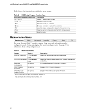
...7 is used to clear the Setup passwords and enable extended configuration mode. Table 7. Displays CPU's Stepping Signature. BIOS Setup Program Function Keys BIOS Setup Program Function Key or or Description Selects a different menu screen Moves cursor up or down Moves cursor to ... the current menu Save the current values and exits the BIOS Setup program Exits the menu Maintenance Menu Maintenance Main Advanced Security Power Boot Exit The menu shown in configure mode. Intel Desktop Boards D845EPT2 and D845EBG2 Product Guide Table 6 shows the function keys available for...
...7 is used to clear the Setup passwords and enable extended configuration mode. Table 7. Displays CPU's Stepping Signature. BIOS Setup Program Function Keys BIOS Setup Program Function Key or or Description Selects a different menu screen Moves cursor up or down Moves cursor to ... the current menu Save the current values and exits the BIOS Setup program Exits the menu Maintenance Menu Maintenance Main Advanced Security Power Boot Exit The menu shown in configure mode. Intel Desktop Boards D845EPT2 and D845EBG2 Product Guide Table 6 shows the function keys available for...


