Product Guide
Page 3
Contents 1 Desktop Board Features Desktop Board Components 9 Processor ...11 Main Memory ...12 Intel® 845E Chipset ...12 Intel® 82845E Memory Controller Hub (MCH 13 Intel® 82801DB I/O Controller Hub (ICH4 13 Firmware Hub (FWH 13 Input/Output (I/O) Controller 13 Audio Subsystem ...14 LAN Subsystem (Optional 14 LAN Subsystem Software 14 RJ-45 ...from PS/2 Keyboard/Mouse 19 PME# Wakeup Support 19 Speaker...20 Battery...20 Real-Time Clock...20 2 Installing and Replacing Desktop Board Components Before You Begin ...21 Installing the I/O Shield...22 Installing and Removing the...
Contents 1 Desktop Board Features Desktop Board Components 9 Processor ...11 Main Memory ...12 Intel® 845E Chipset ...12 Intel® 82845E Memory Controller Hub (MCH 13 Intel® 82801DB I/O Controller Hub (ICH4 13 Firmware Hub (FWH 13 Input/Output (I/O) Controller 13 Audio Subsystem ...14 LAN Subsystem (Optional 14 LAN Subsystem Software 14 RJ-45 ...from PS/2 Keyboard/Mouse 19 PME# Wakeup Support 19 Speaker...20 Battery...20 Real-Time Clock...20 2 Installing and Replacing Desktop Board Components Before You Begin ...21 Installing the I/O Shield...22 Installing and Removing the...

Product Guide
Page 4
Intel Desktop Boards D845EPT2 and D845EBG2 Product Guide Installing and Removing a Processor 24 Installing a Processor 24 Installing the Processor Fan Heat Sink 24 Connecting the Processor Fan Heat Sink Cable 25 ... Setting the BIOS Configuration Jumper Block 30 Installing the Front Panel Audio Solution 31 Clearing Passwords...32 Replacing the Battery ...33 3 Updating the BIOS Updating the BIOS with the Intel® Express BIOS Update Utility 37 Updating the BIOS with the Intel® Flash Memory Update Utility 38 Obtaining the BIOS Update File...
Intel Desktop Boards D845EPT2 and D845EBG2 Product Guide Installing and Removing a Processor 24 Installing a Processor 24 Installing the Processor Fan Heat Sink 24 Connecting the Processor Fan Heat Sink Cable 25 ... Setting the BIOS Configuration Jumper Block 30 Installing the Front Panel Audio Solution 31 Clearing Passwords...32 Replacing the Battery ...33 3 Updating the BIOS Updating the BIOS with the Intel® Express BIOS Update Utility 37 Updating the BIOS with the Intel® Flash Memory Update Utility 38 Obtaining the BIOS Update File...

Product Guide
Page 5
... Reference Connectors...61 Back Panel Connectors 62 Midboard Connectors 63 Audio Connectors 63 Power and Hardware Connectors 64 Add-In Card and Peripheral Interface Connectors 65 Front Panel Headers 67 Desktop Board Resources 68 Memory Map ...68 DMA Channels ...68 Interrupts ... Hardware Control Connectors 64 16. Removing the Battery 35 13. Connecting the IDE Cable 29 11. Desktop Board D845EBG2 Add-in Card and Peripheral Interface Connectors 65 17. Desktop Board D845EBG2 Components 10 3. Removing the AGP Card 28 10. Location of Standby Power Indicator 18 4. Front ...
... Reference Connectors...61 Back Panel Connectors 62 Midboard Connectors 63 Audio Connectors 63 Power and Hardware Connectors 64 Add-In Card and Peripheral Interface Connectors 65 Front Panel Headers 67 Desktop Board Resources 68 Memory Map ...68 DMA Channels ...68 Interrupts ... Hardware Control Connectors 64 16. Removing the Battery 35 13. Connecting the IDE Cable 29 11. Desktop Board D845EBG2 Add-in Card and Peripheral Interface Connectors 65 17. Desktop Board D845EBG2 Components 10 3. Removing the AGP Card 28 10. Location of Standby Power Indicator 18 4. Front ...
Product Guide
Page 6
...BIOS Setup Program Modes (J8H2 30 5. Main Menu...44 10. Floppy Configuration Submenu 52 17. Event Log Configuration Submenu 53 18. Intel Desktop Boards D845EPT2 and D845EBG2 Product Guide Tables 1. BIOS Setup Program Function Keys 42 7. Maintenance Menu ...42 8. Extended Configuration Submenu 43 9. PCI Configuration Submenu... 58 25. Hard Disk Drives Submenu 59 26. Removable Devices Submenu 59 27. Exit Menu...60 29. Front Panel Audio Header Signal Names (J8B1 63 30. System Memory Map 68 32. Interrupts ...69 34. BIOS Error Messages 72 36. EMC Regulations...
...BIOS Setup Program Modes (J8H2 30 5. Main Menu...44 10. Floppy Configuration Submenu 52 17. Event Log Configuration Submenu 53 18. Intel Desktop Boards D845EPT2 and D845EBG2 Product Guide Tables 1. BIOS Setup Program Function Keys 42 7. Maintenance Menu ...42 8. Extended Configuration Submenu 43 9. PCI Configuration Submenu... 58 25. Hard Disk Drives Submenu 59 26. Removable Devices Submenu 59 27. Exit Menu...60 29. Front Panel Audio Header Signal Names (J8B1 63 30. System Memory Map 68 32. Interrupts ...69 34. BIOS Error Messages 72 36. EMC Regulations...
Product Guide
Page 7
...pin count (LPC) interface I /O Control Graphics Audio LAN (optional) Peripheral Interfaces NOTE: The Desktop Boards D845EPT2 and D845EBG2 have been designed to support DIMMs based on 512 Mbit technology up to 2 GB of : • Intel® 82845E Memory Controller Hub (MCH) with... noted. Feature Summary Form Factors Processor Memory • microATX at 8.2 inches by 9.6 inches (Desktop Board D845EPT2) • ATX at : http://support.intel.com/support/motherboards/desktop/ • Intel® 845E chipset consisting of system memory Chipset I /O controller AGP connector supporting 1.5 V 4X...
...pin count (LPC) interface I /O Control Graphics Audio LAN (optional) Peripheral Interfaces NOTE: The Desktop Boards D845EPT2 and D845EBG2 have been designed to support DIMMs based on 512 Mbit technology up to 2 GB of : • Intel® 82845E Memory Controller Hub (MCH) with... noted. Feature Summary Form Factors Processor Memory • microATX at 8.2 inches by 9.6 inches (Desktop Board D845EPT2) • ATX at : http://support.intel.com/support/motherboards/desktop/ • Intel® 845E chipset consisting of system memory Chipset I /O controller AGP connector supporting 1.5 V 4X...

Product Guide
Page 9
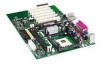
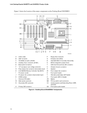
...hard drive activity LED connector F 12 V processor core voltage connector U Chassis intrusion connector G Rear chassis fan connector (tachometer input) V Speaker H Intel 82845E Memory Controller Hub (MCH) W Front chassis fan connector I Processor socket X Front panel header J Processor fan connector (tachometer input) Y ...CC Communication and Networking Riser (CNR) (optional) O Primary IDE connector DD Front panel audio header Figure 1. Desktop Board D845EPT2 Components 9 Desktop Board Features Desktop Board Components Figure 1 shows the location of the major components on the...
...hard drive activity LED connector F 12 V processor core voltage connector U Chassis intrusion connector G Rear chassis fan connector (tachometer input) V Speaker H Intel 82845E Memory Controller Hub (MCH) W Front chassis fan connector I Processor socket X Front panel header J Processor fan connector (tachometer input) Y ...CC Communication and Networking Riser (CNR) (optional) O Primary IDE connector DD Front panel audio header Figure 1. Desktop Board D845EPT2 Components 9 Desktop Board Features Desktop Board Components Figure 1 shows the location of the major components on the...
Product Guide
Page 10
... G CC H BB I AA J Z Y K X L W VU T S R Q P O N M OM13672 A Audio codec P Floppy drive connector B AGP connector Q Firmware Hub (FWH) C CD-ROM connector (ATAPI) R Intel 82801DB I/O Controller Hub (ICH4) D Auxiliary line-in connector (ATAPI) S BIOS configuration jumper block E Back panel connectors T SCSI ... and Networking Riser (CNR) (optional) O Primary IDE connector DD Front panel audio header Figure 2. Desktop Board D845EBG2 Components 10 Intel Desktop Boards D845EPT2 and D845EBG2 Product Guide Figure 2 shows the location of the major components on the...
... G CC H BB I AA J Z Y K X L W VU T S R Q P O N M OM13672 A Audio codec P Floppy drive connector B AGP connector Q Firmware Hub (FWH) C CD-ROM connector (ATAPI) R Intel 82801DB I/O Controller Hub (ICH4) D Auxiliary line-in connector (ATAPI) S BIOS configuration jumper block E Back panel connectors T SCSI ... and Networking Riser (CNR) (optional) O Primary IDE connector DD Front panel audio header Figure 2. Desktop Board D845EBG2 Components 10 Intel Desktop Boards D845EPT2 and D845EBG2 Product Guide Figure 2 shows the location of the major components on the...

Product Guide
Page 13
...Controller Hub (MCH) The MCH provides the processor, system memory, AGP, and hub interfaces in the Intel 845E chipset platform. Features on Desktop Boards D845EPT2 and D845EBG2 include: • Single processor support with 533/400 MHz data transfer rate • Designed to support ...Desktop Boards D845EPT2 and D845EBG2 include: • Integrated IDE controller supports two Ultra DMA-33 and ATA-66/100 channels, and PIO modes • SMBus interface • FWH interface • Low Pin Count (LPC) interface • AC'97 2.1 compliant link for audio and telephony codecs • Integrated Intel...
...Controller Hub (MCH) The MCH provides the processor, system memory, AGP, and hub interfaces in the Intel 845E chipset platform. Features on Desktop Boards D845EPT2 and D845EBG2 include: • Single processor support with 533/400 MHz data transfer rate • Designed to support ...Desktop Boards D845EPT2 and D845EBG2 include: • Integrated IDE controller supports two Ultra DMA-33 and ATA-66/100 channels, and PIO modes • SMBus interface • FWH interface • Low Pin Count (LPC) interface • AC'97 2.1 compliant link for audio and telephony codecs • Integrated Intel...

Product Guide
Page 14
... utilities are connected to this output. Intel Desktop Boards D845EPT2 and D845EBG2 Product Guide Audio Subsystem The audio subsystem features the following functions: • Basic 10/100 Ethernet LAN connectivity • Supports RJ-45 connector with the Intel 82801DB ICH4) provides a Fast PCI LAN ...Analog Devices AD1981A audio codec ✏ NOTE The line out connector, located on the LAN. 14 Yellow Off LAN link is designed to the Desktop Board D845EPT2 or D845EBG2 link on Intel's World Wide Web site at: http://support.intel.com/support/motherboards/desktop RJ-45 LAN...
... utilities are connected to this output. Intel Desktop Boards D845EPT2 and D845EBG2 Product Guide Audio Subsystem The audio subsystem features the following functions: • Basic 10/100 Ethernet LAN connectivity • Supports RJ-45 connector with the Intel 82801DB ICH4) provides a Fast PCI LAN ...Analog Devices AD1981A audio codec ✏ NOTE The line out connector, located on the LAN. 14 Yellow Off LAN link is designed to the Desktop Board D845EPT2 or D845EBG2 link on Intel's World Wide Web site at: http://support.intel.com/support/motherboards/desktop RJ-45 LAN...

Product Guide
Page 16
...The optional CNR provides an interface that add-in card. The BIOS is intended for exclusive use with PCI bus connector 3) The Desktop Board D845EBG2 has: • Six PCI bus add-in card. 16 BIOS The BIOS provides the Power-On Self-Test (POST), the ... the resources (IRQs, DMA channels, and I/O space) for graphics-intensive applications, such as audio, modem, and LAN. Intel Desktop Boards D845EPT2 and D845EBG2 Product Guide Expansion Slots The Desktop Boards D845EPT2 and D845EBG2 have the following the instructions in Chapter 3 on page 21. PCI Auto Configuration If you ...
...The optional CNR provides an interface that add-in card. The BIOS is intended for exclusive use with PCI bus connector 3) The Desktop Board D845EBG2 has: • Six PCI bus add-in card. 16 BIOS The BIOS provides the Power-On Self-Test (POST), the ... the resources (IRQs, DMA channels, and I/O space) for graphics-intensive applications, such as audio, modem, and LAN. Intel Desktop Boards D845EPT2 and D845EBG2 Product Guide Expansion Slots The Desktop Boards D845EPT2 and D845EBG2 have the following the instructions in Chapter 3 on page 21. PCI Auto Configuration If you ...

Product Guide
Page 21
...any procedures can result in personal injury or equipment damage. 2 Installing and Replacing Desktop Board Components This chapter tells you how to: • Install the I/O shield • Install and remove the desktop board • Install and remove a processor • Install and remove memory &#...8226; Install and remove an AGP card • Connect the IDE cable • Set the BIOS jumper • Install the front panel audio solution • Clear passwords •...
...any procedures can result in personal injury or equipment damage. 2 Installing and Replacing Desktop Board Components This chapter tells you how to: • Install the I/O shield • Install and remove the desktop board • Install and remove a processor • Install and remove memory &#...8226; Install and remove an AGP card • Connect the IDE cable • Set the BIOS jumper • Install the front panel audio solution • Clear passwords •...

Product Guide
Page 31
... page 21. 2. Turn off all peripheral devices connected to disable the back panel audio connectors. 6. Installing and Replacing Desktop Board Components Installing the Front Panel Audio Solution To install the cable that connects the front panel audio solution to the front panel audio header, follow these steps: 1. Observe the precautions in "Before You Begin" on pins...
... page 21. 2. Turn off all peripheral devices connected to disable the back panel audio connectors. 6. Installing and Replacing Desktop Board Components Installing the Front Panel Audio Solution To install the cable that connects the front panel audio solution to the front panel audio header, follow these steps: 1. Observe the precautions in "Before You Begin" on pins...
Product Guide
Page 49
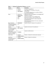
... Submenu (continued) Feature Parallel Port Mode Base I /O address for the parallel port. Specifies the interrupt for the parallel port. An * (asterisk) displayed next to ECP) Audio Device LAN Device (This feature is present only when there is Enhanced Capabilities Port mode, a high-speed bi-directional mode. Not available if the parallel... Selects the mode for the parallel port. EPP is disabled. Auto assigns LPT1 the address 378h and the interrupt IRQ7. Enables or disables the onboard audio subsystem. Output Only operates in PS/2-compatible mode.
... Submenu (continued) Feature Parallel Port Mode Base I /O address for the parallel port. Specifies the interrupt for the parallel port. An * (asterisk) displayed next to ECP) Audio Device LAN Device (This feature is present only when there is Enhanced Capabilities Port mode, a high-speed bi-directional mode. Not available if the parallel... Selects the mode for the parallel port. EPP is disabled. Auto assigns LPT1 the address 378h and the interrupt IRQ7. Enables or disables the onboard audio subsystem. Output Only operates in PS/2-compatible mode.

Product Guide
Page 61
... could cause damage to the computer, the interconnecting cable, and the external devices themselves. 61 5 Technical Reference Connectors The Intel desktop board connectors can be divided into three groups: • Back panel connectors • Midboard connectors - Do not use these ...connectors for example) to the computer chassis. A fault in board and peripheral interface connectors • Front panel headers CAUTION Many of the midboard and front panel connectors provide operating voltage (+5 V dc...
... could cause damage to the computer, the interconnecting cable, and the external devices themselves. 61 5 Technical Reference Connectors The Intel desktop board connectors can be divided into three groups: • Back panel connectors • Midboard connectors - Do not use these ...connectors for example) to the computer chassis. A fault in board and peripheral interface connectors • Front panel headers CAUTION Many of the midboard and front panel connectors provide operating voltage (+5 V dc...

Product Guide
Page 62
Back Panel Connectors ✏ NOTE The line out connector, located on the back panel, is designed to this output. 62 Intel Desktop Boards D845EPT2 and D845EBG2 Product Guide Back Panel Connectors Figure 13 shows the back panel connectors. A E G C BD F H I J KL Item A B C D E F G H I J K L Description PS/2 mouse ...-45 (optional) USB 2.0 port USB 2.0 port Mic in Audio line out Audio line in Color Green Purple Black Black Burgundy Teal Black Black Black Pink Lime green Light blue OM13662 Figure 13. Poor audio quality may occur if passive (non-amplified) speakers are connected ...
Back Panel Connectors ✏ NOTE The line out connector, located on the back panel, is designed to this output. 62 Intel Desktop Boards D845EPT2 and D845EBG2 Product Guide Back Panel Connectors Figure 13 shows the back panel connectors. A E G C BD F H I J KL Item A B C D E F G H I J K L Description PS/2 mouse ...-45 (optional) USB 2.0 port USB 2.0 port Mic in Audio line out Audio line in Color Green Purple Black Black Burgundy Teal Black Black Black Pink Lime green Light blue OM13662 Figure 13. Poor audio quality may occur if passive (non-amplified) speakers are connected ...

Product Guide
Page 63
... Figure 14 shows the location of the audio connectors. Front Panel Audio Header Signal Names (J8B1) Pin Signal Name 1 AUD-MIC 3 AUD-MIC-BIAS 5 AUD-FPOUT-R 7 HP-ON 9 AUD-FPOUT-L Pin Signal Name 2 AUD-GND 4... AUD-VCC 6 AUD-RET-R 8 KEY 10 AUD-RET-L OM13661 Color Black White Black 63 B C 1 2 3 4 A 5 6 7 9 10 1 4 4 1 Technical Reference Item A B C Description Front panel audio (see Table 29 for the front panel audio header. Audio Connectors Table 29 shows the pin assignments for pin assignments) Auxiliary line in CD-ROM Figure 14. Table 29.
... Figure 14 shows the location of the audio connectors. Front Panel Audio Header Signal Names (J8B1) Pin Signal Name 1 AUD-MIC 3 AUD-MIC-BIAS 5 AUD-FPOUT-R 7 HP-ON 9 AUD-FPOUT-L Pin Signal Name 2 AUD-GND 4... AUD-VCC 6 AUD-RET-R 8 KEY 10 AUD-RET-L OM13661 Color Black White Black 63 B C 1 2 3 4 A 5 6 7 9 10 1 4 4 1 Technical Reference Item A B C Description Front panel audio (see Table 29 for the front panel audio header. Audio Connectors Table 29 shows the pin assignments for pin assignments) Auxiliary line in CD-ROM Figure 14. Table 29.

Product Guide
Page 67
... USB_FP_OC0 67 Front Panel Headers Figure 18 shows the location of the front panel headers. 1 2 3 4 A 5 6 7 10 Technical Reference 8 C 6 4 2 1 2 3 4 B5 6 7 8 10 9 7 5 3 1 Item A B C D D OM13658 Description Front panel audio (see Table 29 on page 63 for pin assignments) Front panel USB 2.0 (see Table 30 for the front panel USB 2.0 header. Table 30. Front Panel...
... USB_FP_OC0 67 Front Panel Headers Figure 18 shows the location of the front panel headers. 1 2 3 4 A 5 6 7 10 Technical Reference 8 C 6 4 2 1 2 3 4 B5 6 7 8 10 9 7 5 3 1 Item A B C D D OM13658 Description Front panel audio (see Table 29 on page 63 for pin assignments) Front panel USB 2.0 (see Table 30 for the front panel USB 2.0 header. Table 30. Front Panel...


