
Product Guide
Page 2
... intended for a particular purpose, merchantability, or infringement of any time, without notice. Revision History Revision -001 Revision History First release of the Desktop Boards D815EEA2, D815EPEA2, D815EFV, and D815EPFV Product Guide Intel® Date March 2001 If an FCC declaration of conformity marking is present on , the user is encouraged to try to correct the...
... intended for a particular purpose, merchantability, or infringement of any time, without notice. Revision History Revision -001 Revision History First release of the Desktop Boards D815EEA2, D815EPEA2, D815EFV, and D815EPFV Product Guide Intel® Date March 2001 If an FCC declaration of conformity marking is present on , the user is encouraged to try to correct the...

Product Guide
Page 4
Intel Desktop Boards D815EEA2, D815EPEA2, D815EFV, and D815EPFV Product Guide Installing and Removing AGP and GPA Cards ...31 Installing an AGP Card ...31 Removing the AGP Card from the Retention Mechanism ...31 Installing and Removing a GPA Card (D815EEA2 and D815EFV only) ...32 Installing the I/O Shield ...33 Installing the Desktop Board...34 Installing a Processor ...36 Removing the Processor ...38 Installing...
Intel Desktop Boards D815EEA2, D815EPEA2, D815EFV, and D815EPFV Product Guide Installing and Removing AGP and GPA Cards ...31 Installing an AGP Card ...31 Removing the AGP Card from the Retention Mechanism ...31 Installing and Removing a GPA Card (D815EEA2 and D815EFV only) ...32 Installing the I/O Shield ...33 Installing the Desktop Board...34 Installing a Processor ...36 Removing the Processor ...38 Installing...
Product Guide
Page 5
... to the Processor ...37 Attaching the Fan Heatsink Clips to the Processor Socket ...37 v D815EEA2 and D815EPEA2 Desktop Board Components...12 D815EFV and D815EPFV Desktop Board Components ...13 Location of Standby Power Indicator (the D815EEA2 Board Is Shown)...24 DIMM Socket Locations (the D815EEA2 Board Is Shown) ...27 Retention Notch Shown on an AGP Card ...28 AGP Connector Location and...
... to the Processor ...37 Attaching the Fan Heatsink Clips to the Processor Socket ...37 v D815EEA2 and D815EPEA2 Desktop Board Components...12 D815EFV and D815EPFV Desktop Board Components ...13 Location of Standby Power Indicator (the D815EEA2 Board Is Shown)...24 DIMM Socket Locations (the D815EEA2 Board Is Shown) ...27 Retention Notch Shown on an AGP Card ...28 AGP Connector Location and...
Product Guide
Page 6
...Options...11 Supported Processors ...14 Processor and Memory Module Combinations...16 RJ-45 LAN Connector LEDs ...22 Jumper Settings for the D815EEA2 and D815EPEA2 Boards ...83 32. Intel Desktop Boards D815EEA2, D815EPEA2, D815EFV, and D815EPFV Product Guide 16. 17. 18. 19. 20. 21. 22. 23. 24. 25. ...26. 27. 28. 29. 30. 31. Front Panel Connectors (the D815EEA2 Board Is Shown) ...85 Tables 1. 2. 3. 4. 5. 6. 7. 8. 9. 10. 11. 12. 13. 14. 15. 16. 17...
...Options...11 Supported Processors ...14 Processor and Memory Module Combinations...16 RJ-45 LAN Connector LEDs ...22 Jumper Settings for the D815EEA2 and D815EPEA2 Boards ...83 32. Intel Desktop Boards D815EEA2, D815EPEA2, D815EFV, and D815EPFV Product Guide 16. 17. 18. 19. 20. 21. 22. 23. 24. 25. ...26. 27. 28. 29. 30. 31. Front Panel Connectors (the D815EEA2 Board Is Shown) ...85 Tables 1. 2. 3. 4. 5. 6. 7. 8. 9. 10. 11. 12. 13. 14. 15. 16. 17...

Product Guide
Page 9
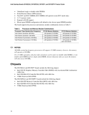
Table 2. AD1885 audio codec continued 9 1 Desktop Board Features Table 1 describes the major differences between the boards. Table 1. Feature Summary Specification • ATX at 11.55 inches by 8.20 inches (D815EEA2 and D815EPEA2) • microATX at 9.6 inches by 8.2 inches (D815EFV and D815EPFV) Processors • Intel® Pentium® III processor family with FC-PGA (Flip Chip Pin Grid...
Table 2. AD1885 audio codec continued 9 1 Desktop Board Features Table 1 describes the major differences between the boards. Table 1. Feature Summary Specification • ATX at 11.55 inches by 8.20 inches (D815EEA2 and D815EPEA2) • microATX at 9.6 inches by 8.2 inches (D815EFV and D815EPFV) Processors • Intel® Pentium® III processor family with FC-PGA (Flip Chip Pin Grid...

Product Guide
Page 10
Intel Desktop Boards D815EEA2, D815EPEA2, D815EFV, and D815EPFV Product Guide Table 2. Video Feature Summary (continued) Specification • The D815EEA2 and D815EFV boards include: Intel 82815E integrated graphics support AGP universal connector supporting 1x, 2x, or 4x AGP cards or a Graphics Performance Accelerator (GPA) Characteristic Rear panel VGA connector • The D815EPEA2 and D815EPFV boards include an AGP universal...
Intel Desktop Boards D815EEA2, D815EPEA2, D815EFV, and D815EPFV Product Guide Table 2. Video Feature Summary (continued) Specification • The D815EEA2 and D815EFV boards include: Intel 82815E integrated graphics support AGP universal connector supporting 1x, 2x, or 4x AGP cards or a Graphics Performance Accelerator (GPA) Characteristic Rear panel VGA connector • The D815EPEA2 and D815EPFV boards include an AGP universal...

Product Guide
Page 11
... or TV out (D815EEA2 and D815EFV boards only). Intel® 82562ET that provides a basic interface to the RJ-45 connector with PCI bus connector 3 on D815EFV and D815EPFV boards. Characteristic Communication and ...Manufacturing Options Specification One CNR connector: • Slot shared with PCI bus connector 5 on D815EEA2 and D815EPEA2 boards. • Slot shared with integrated LED's located on (WOL) Technology Connector LAN Routes ...LPC47M142 LPC bus I /O controller. Table 3. Desktop Board Features Manufacturing Options Table 3 describes the manufacturing options of the...
... or TV out (D815EEA2 and D815EFV boards only). Intel® 82562ET that provides a basic interface to the RJ-45 connector with PCI bus connector 3 on D815EFV and D815EPFV boards. Characteristic Communication and ...Manufacturing Options Specification One CNR connector: • Slot shared with PCI bus connector 5 on D815EEA2 and D815EPEA2 boards. • Slot shared with integrated LED's located on (WOL) Technology Connector LAN Routes ...LPC47M142 LPC bus I /O controller. Table 3. Desktop Board Features Manufacturing Options Table 3 describes the manufacturing options of the...

Product Guide
Page 12
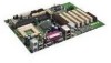
...Components labeled optional do not come on the D815EEA2 and D815EPEA2 boards. AD1885 audio codec AGP universal connector ATAPI-style auxiliary line in card connectors Figure 1. Intel Desktop Boards D815EEA2, D815EPEA2, D815EFV, and D815EPFV Product Guide Components Figure 1 shows the major components on all the boards. 12 A B C DE F G ... Processor fan connector (fan 1, tach) Digital Video Output (DVO) connector (D815EEA2 only) • Intel 82815E GMCH (D815EEA2 only) • Intel 82815EP MCH (D815EPEA2 only) 370-pin processor socket DIMM sockets Chassis fan connector (fan 3) Speaker...
...Components labeled optional do not come on the D815EEA2 and D815EPEA2 boards. AD1885 audio codec AGP universal connector ATAPI-style auxiliary line in card connectors Figure 1. Intel Desktop Boards D815EEA2, D815EPEA2, D815EFV, and D815EPFV Product Guide Components Figure 1 shows the major components on all the boards. 12 A B C DE F G ... Processor fan connector (fan 1, tach) Digital Video Output (DVO) connector (D815EEA2 only) • Intel 82815E GMCH (D815EEA2 only) • Intel 82815EP MCH (D815EPEA2 only) 370-pin processor socket DIMM sockets Chassis fan connector (fan 3) Speaker...

Product Guide
Page 14
... installing or upgrading the processor, see Chapter 2. 14 Intel Desktop Boards D815EEA2, D815EPEA2, D815EFV, and D815EPFV Product Guide Processors CAUTION Use only the processors listed below. See the Intel Desktop D815EA2/D815EPEA2 or D815EFV/D815EPFV Specification Update for theD815EEA2, D815EPEA2, D815EFV, and D815EPFV boards. The boards support a single Intel Pentium III processor or Intel Celeron processor above 533 MHz. Use of supported processors...
... installing or upgrading the processor, see Chapter 2. 14 Intel Desktop Boards D815EEA2, D815EPEA2, D815EFV, and D815EPFV Product Guide Processors CAUTION Use only the processors listed below. See the Intel Desktop D815EA2/D815EPEA2 or D815EFV/D815EPFV Specification Update for theD815EEA2, D815EPEA2, D815EFV, and D815EPFV boards. The boards support a single Intel Pentium III processor or Intel Celeron processor above 533 MHz. Use of supported processors...
Product Guide
Page 16
... default to RAM support Mixed speed DIMM configuration will support 133 MHz memory; The board supports the processor and memory module combinations shown in non-ECC mode only) 3.3 V memory (only) Suspend to the slowest speed DIMM installed. Table 5. Intel Desktop Boards D815EEA2, D815EPEA2, D815EFV, and D815EPFV Product Guide Unbuffered single or double-sided DIMMs Serial Presence...
... default to RAM support Mixed speed DIMM configuration will support 133 MHz memory; The board supports the processor and memory module combinations shown in non-ECC mode only) 3.3 V memory (only) Suspend to the slowest speed DIMM installed. Table 5. Intel Desktop Boards D815EEA2, D815EPEA2, D815EFV, and D815EPFV Product Guide Unbuffered single or double-sided DIMMs Serial Presence...
Product Guide
Page 18
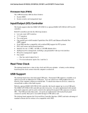
...optional SMSC LPC47M142 LPC bus I/O controller. To attach more than two devices, connect an external hub to provide an additional two USB ports. Intel Desktop Boards D815EEA2, D815EPEA2, D815EFV, and D815EPFV Product Guide Firmware Hub (FWH) The 4 Mbit Firmware Hub has these features: • • System BIOS System...control One fan control output (fan 2) Two fan tachometer inputs (fan 1 and fan 2) Real-Time Clock The desktop boards have four back panel USB ports. The ICH2 provides three ports: two ports are implemented with serialized IRQ support for PCI systems PS/2-...
...optional SMSC LPC47M142 LPC bus I/O controller. To attach more than two devices, connect an external hub to provide an additional two USB ports. Intel Desktop Boards D815EEA2, D815EPEA2, D815EFV, and D815EPFV Product Guide Firmware Hub (FWH) The 4 Mbit Firmware Hub has these features: • • System BIOS System...control One fan control output (fan 2) Two fan tachometer inputs (fan 1 and fan 2) Real-Time Clock The desktop boards have four back panel USB ports. The ICH2 provides three ports: two ports are implemented with serialized IRQ support for PCI systems PS/2-...
Product Guide
Page 20
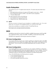
...100 operating system device drivers 20 Poor audio quality may occur if passive (non-amplified) speakers are available from Intel's World Wide Web site: http://support.intel.com/support/motherboards/desktop BIOS The BIOS provides the Power-On Self-Test (POST), the BIOS Setup program, the PCI and IDE ... Hub (ICH2) Analog Devices Inc. To use ATA-66/100 features, the following : ✏ NOTE The line out connector is stored in Chapter 3. Intel Desktop Boards D815EEA2, D815EPEA2, D815EFV, and D815EPFV Product Guide Audio Subsystem The boards have an AC '97 compliant audio subsystem.
...100 operating system device drivers 20 Poor audio quality may occur if passive (non-amplified) speakers are available from Intel's World Wide Web site: http://support.intel.com/support/motherboards/desktop BIOS The BIOS provides the Power-On Self-Test (POST), the BIOS Setup program, the PCI and IDE ... Hub (ICH2) Analog Devices Inc. To use ATA-66/100 features, the following : ✏ NOTE The line out connector is stored in Chapter 3. Intel Desktop Boards D815EEA2, D815EPEA2, D815EFV, and D815EPFV Product Guide Audio Subsystem The boards have an AC '97 compliant audio subsystem.
Product Guide
Page 22
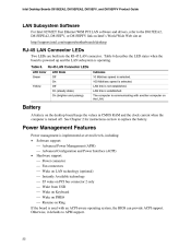
... ACPI support. Power Management Features Power management is implemented at : http://support.intel.com/support/motherboards/desktop RJ-45 LAN Connector LEDs Two LEDs are built into the RJ-45 LAN connector. Otherwise, it defaults to replace the battery. The computer is operating. Table 6. Intel Desktop Boards D815EEA2, D815EPEA2, D815EFV, and D815EPFV Product Guide LAN Subsystem Software For...
... ACPI support. Power Management Features Power management is implemented at : http://support.intel.com/support/motherboards/desktop RJ-45 LAN Connector LEDs Two LEDs are built into the RJ-45 LAN connector. Otherwise, it defaults to replace the battery. The computer is operating. Table 6. Intel Desktop Boards D815EEA2, D815EPEA2, D815EFV, and D815EPFV Product Guide LAN Subsystem Software For...

Product Guide
Page 23
...the standby current necessary to provide adequate standby current when implementing Wake on LAN technology can damage the power supply. The desktop board standby power indicator, shown in the S3 sleep state, the computer will appear to be off . When signaled by ...capable of providing adequate +5-V standby current. For more information about front panel LED states, see the Intel ® Desktop Board D815EEA2/D815EPEA2 Technical Product Specification or Intel ® Desktop Board D815EFV/D815EPFV Technical Product Specification. 23 See Figure 30 on page 82 for the power supply must be...
...the standby current necessary to provide adequate standby current when implementing Wake on LAN technology can damage the power supply. The desktop board standby power indicator, shown in the S3 sleep state, the computer will appear to be off . When signaled by ...capable of providing adequate +5-V standby current. For more information about front panel LED states, see the Intel ® Desktop Board D815EEA2/D815EPEA2 Technical Product Specification or Intel ® Desktop Board D815EFV/D815EPFV Technical Product Specification. 23 See Figure 30 on page 82 for the power supply must be...

Product Guide
Page 24
... the computer Detects incoming call similarly for external and internal modems Requires modem interrupt be unmasked for more information. Location of standby current is recommended. Intel Desktop Boards D815EEA2, D815EPEA2, D815EFV, and D815EPFV Product Guide CR6F1 STR LED OM11632 Figure 3. If the standby current necessary to support multiple wake events from either the APM sleep...
... the computer Detects incoming call similarly for external and internal modems Requires modem interrupt be unmasked for more information. Location of standby current is recommended. Intel Desktop Boards D815EEA2, D815EPEA2, D815EFV, and D815EPFV Product Guide CR6F1 STR LED OM11632 Figure 3. If the standby current necessary to support multiple wake events from either the APM sleep...
Product Guide
Page 26
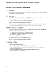
...). 2. DIMM Installation Guidelines All memory components and DIMMs used with the boards must comply with the memory retention mechanism. Turn off all applicable Intel ® SDRAM memory specifications, the boards require DIMMs that support the Serial Presence Detect (SPD) data structure. ... 1, and 2 as shown Figure 4. Remove the AGP video card (if installed). 26 You can access these steps: 1. Intel Desktop Boards D815EEA2, D815EPEA2, D815EFV, and D815EPFV Product Guide Installing and Removing Memory CAUTION Install memory in the DIMM sockets prior to installing the AGP video ...
...). 2. DIMM Installation Guidelines All memory components and DIMMs used with the boards must comply with the memory retention mechanism. Turn off all applicable Intel ® SDRAM memory specifications, the boards require DIMMs that support the Serial Presence Detect (SPD) data structure. ... 1, and 2 as shown Figure 4. Remove the AGP video card (if installed). 26 You can access these steps: 1. Intel Desktop Boards D815EEA2, D815EPEA2, D815EFV, and D815EPFV Product Guide Installing and Removing Memory CAUTION Install memory in the DIMM sockets prior to installing the AGP video ...

Product Guide
Page 28
Use of the RM with unnotched cards. OM10218 Figure 5. Intel Desktop Boards D815EEA2, D815EPEA2, D815EFV, and D815EPFV Product Guide Installing and Removing the AGP Card Retention Mechanism The AGP universal connector supports AGP (1x, 2x, and 4x... card may impair operation. Retention Notch Shown on an AGP Card The RM encloses the desktop board's AGP connector and provides additional mechanical stability to remove the RM, follow the instructions on D815EEA2 and D815EFV boards only) cards. Installing the AGP Card Retention Mechanism CAUTION Install the retention mechanism (RM)...
Use of the RM with unnotched cards. OM10218 Figure 5. Intel Desktop Boards D815EEA2, D815EPEA2, D815EFV, and D815EPFV Product Guide Installing and Removing the AGP Card Retention Mechanism The AGP universal connector supports AGP (1x, 2x, and 4x... card may impair operation. Retention Notch Shown on an AGP Card The RM encloses the desktop board's AGP connector and provides additional mechanical stability to remove the RM, follow the instructions on D815EEA2 and D815EFV boards only) cards. Installing the AGP Card Retention Mechanism CAUTION Install the retention mechanism (RM)...

Product Guide
Page 30
..., the AGP RM cannot be snapped off of the retention mechanism. 2. Spread the sides of the retention mechanism (C) and lift the retention mechanism off the board. Intel Desktop Boards D815EEA2, D815EPEA2, D815EFV, and D815EPFV Product Guide Removing the AGP Card Retention Mechanism The removal instructions below are for AGP card retention mechanisms that cannot easily be...
..., the AGP RM cannot be snapped off of the retention mechanism. 2. Spread the sides of the retention mechanism (C) and lift the retention mechanism off the board. Intel Desktop Boards D815EEA2, D815EPEA2, D815EFV, and D815EPFV Product Guide Removing the AGP Card Retention Mechanism The removal instructions below are for AGP card retention mechanisms that cannot easily be...

Product Guide
Page 32
... card's edge plug is not positioned squarely over the AGP connector before installing or upgrading memory to install a GPA card: 1. Intel Desktop Boards D815EEA2, D815EPEA2, D815EFV, and D815EPFV Product Guide Installing and Removing a GPA Card (D815EEA2 and D815EFV only) CAUTION Remove the GPA video card before inserting. Hook the notch (B) on the GPA card points toward...
... card's edge plug is not positioned squarely over the AGP connector before installing or upgrading memory to install a GPA card: 1. Intel Desktop Boards D815EEA2, D815EPEA2, D815EFV, and D815EPFV Product Guide Installing and Removing a GPA Card (D815EEA2 and D815EFV only) CAUTION Remove the GPA video card before inserting. Hook the notch (B) on the GPA card points toward...

Product Guide
Page 34
Refer to Appendix B for the D815EEA2 and D815EPEA2 Boards 34 Figure 11 and Figure 12 respectively show the locations of the Mounting Screw Holes for regulatory requirements and ... equipment damage. CAUTION Only qualified technical personnel should attempt this procedure. Seven screws for the D815EEA2 and D815EPEA2 boards and six screws for instructions on installing the desktop board. OM11625 Figure 11. Intel Desktop Boards D815EEA2, D815EPEA2, D815EFV, and D815EPFV Product Guide Installing the Desktop Board Refer to your chassis manual for the D815EFV and D815EPFV...
Refer to Appendix B for the D815EEA2 and D815EPEA2 Boards 34 Figure 11 and Figure 12 respectively show the locations of the Mounting Screw Holes for regulatory requirements and ... equipment damage. CAUTION Only qualified technical personnel should attempt this procedure. Seven screws for the D815EEA2 and D815EPEA2 boards and six screws for instructions on installing the desktop board. OM11625 Figure 11. Intel Desktop Boards D815EEA2, D815EPEA2, D815EFV, and D815EPFV Product Guide Installing the Desktop Board Refer to your chassis manual for the D815EFV and D815EPFV...