Product Guide
Page 3
Contents 1 Desktop Board Features Manufacturing Options ...11 Components...12 Processors ...14 Main Memory ...15 Chipsets ...16 Intel® 82815E Graphics Memory Controller Hub (GMCH) ...17 Intel® 82815EP Memory Controller Hub (MCH) ...17 Intel® 82801BA I/O Controller Hub (ICH2) ...17 Firmware Hub (FWH) ...18 Input/Output (I/O) Controller...18 Real-Time Clock...18 USB Support ...18 PCI Enhanced...
Contents 1 Desktop Board Features Manufacturing Options ...11 Components...12 Processors ...14 Main Memory ...15 Chipsets ...16 Intel® 82815E Graphics Memory Controller Hub (GMCH) ...17 Intel® 82815EP Memory Controller Hub (MCH) ...17 Intel® 82801BA I/O Controller Hub (ICH2) ...17 Firmware Hub (FWH) ...18 Input/Output (I/O) Controller...18 Real-Time Clock...18 USB Support ...18 PCI Enhanced...

Product Guide
Page 4
Intel Desktop Boards D815EEA2, D815EPEA2, D815EFV, and D815EPFV Product Guide Installing and Removing AGP and GPA Cards ...31 Installing an AGP Card ...31 Removing the AGP Card from the Retention Mechanism ...31 Installing and Removing a GPA Card (D815EEA2 and D815EFV only) ...32 Installing the I/O Shield ...33 Installing the Desktop Board...34 Installing a Processor ...36 Removing the Processor ...38 Installing a 1 GHz...
Intel Desktop Boards D815EEA2, D815EPEA2, D815EFV, and D815EPFV Product Guide Installing and Removing AGP and GPA Cards ...31 Installing an AGP Card ...31 Removing the AGP Card from the Retention Mechanism ...31 Installing and Removing a GPA Card (D815EEA2 and D815EFV only) ...32 Installing the I/O Shield ...33 Installing the Desktop Board...34 Installing a Processor ...36 Removing the Processor ...38 Installing a 1 GHz...
Product Guide
Page 5
...D815EEA2 and D815EPEA2 Desktop Board Components...12 D815EFV and D815EPFV Desktop Board Components ...13 Location of Standby Power Indicator (the D815EEA2 Board Is Shown)...24 DIMM Socket Locations (the D815EEA2 Board Is Shown) ...27 Retention Notch Shown on an AGP Card ...28 AGP Connector Location and Retention Mechanism (RM) Placement (Inset) (the D815EEA2 Board... Overload...94 Place Battery Marking ...94 Use Only for the D815EFV and D815EPFV Boards...35 Installing the Processor in the Processor Socket ...36 Attaching the Heatsink to the Processor ...37 Attaching the Fan Heatsink Clips to the...
...D815EEA2 and D815EPEA2 Desktop Board Components...12 D815EFV and D815EPFV Desktop Board Components ...13 Location of Standby Power Indicator (the D815EEA2 Board Is Shown)...24 DIMM Socket Locations (the D815EEA2 Board Is Shown) ...27 Retention Notch Shown on an AGP Card ...28 AGP Connector Location and Retention Mechanism (RM) Placement (Inset) (the D815EEA2 Board... Overload...94 Place Battery Marking ...94 Use Only for the D815EFV and D815EPFV Boards...35 Installing the Processor in the Processor Socket ...36 Attaching the Heatsink to the Processor ...37 Attaching the Fan Heatsink Clips to the...
Product Guide
Page 6
...Processor Fan Connector ...41 Removing the Fan Heatsink...42 Removing the Battery from the D815EEA2 and D815EPEA2 Boards ...45 Removing the Battery from the D815EFV and D815EPFV Boards ...46 Connecting the IDE Cable (the D815EEA2 Board Is Shown)...47 BIOS Configuration Jumper Block Location (the D815EEA2 Board Is Shown) ...48 Connector Groups (the D815EEA2 Board... Configuration Submenu ...69 Video Configuration Submenu ...70 Security Menu...71 Power Menu...72 APM Submenu...73 vi Intel Desktop Boards D815EEA2, D815EPEA2, D815EFV, and D815EPFV Product Guide 16. 17. 18. 19. 20. 21. 22. 23. 24. 25...
...Processor Fan Connector ...41 Removing the Fan Heatsink...42 Removing the Battery from the D815EEA2 and D815EPEA2 Boards ...45 Removing the Battery from the D815EFV and D815EPFV Boards ...46 Connecting the IDE Cable (the D815EEA2 Board Is Shown)...47 BIOS Configuration Jumper Block Location (the D815EEA2 Board Is Shown) ...48 Connector Groups (the D815EEA2 Board... Configuration Submenu ...69 Video Configuration Submenu ...70 Security Menu...71 Power Menu...72 APM Submenu...73 vi Intel Desktop Boards D815EEA2, D815EPEA2, D815EFV, and D815EPFV Product Guide 16. 17. 18. 19. 20. 21. 22. 23. 24. 25...

Product Guide
Page 9
... processors) Chipsets • The D815EEA2 and D815EFV boards include the Intel 815E Chipset, consisting of: Intel 82815E Graphics Memory Controller Hub (GMCH) Intel&#...Board Name D815EEA2 and D815EFV Table 2 describes the major features of : Intel 82815EP Memory Controller Hub (MCH) I/O Control Audio Intel 82801BA I/O Controller Hub (ICH2) 4 Mbit Firmware Hub (FWH) SMSC LPC47M132 LPC bus I/O controller An audio subsystem that includes the: • Intel 82801BA ICH2 digital controller (AC link output) • Analog Devices Inc. 1 Desktop Board...
... processors) Chipsets • The D815EEA2 and D815EFV boards include the Intel 815E Chipset, consisting of: Intel 82815E Graphics Memory Controller Hub (GMCH) Intel&#...Board Name D815EEA2 and D815EFV Table 2 describes the major features of : Intel 82815EP Memory Controller Hub (MCH) I/O Control Audio Intel 82801BA I/O Controller Hub (ICH2) 4 Mbit Firmware Hub (FWH) SMSC LPC47M132 LPC bus I/O controller An audio subsystem that includes the: • Intel 82801BA ICH2 digital controller (AC link output) • Analog Devices Inc. 1 Desktop Board...

Product Guide
Page 12
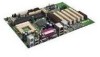
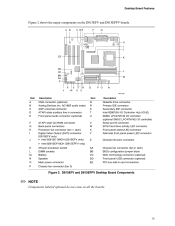
... (D815EPEA2 only) 370-pin processor socket DIMM sockets Chassis fan connector (fan 3) Speaker Main power connector Diskette drive connector Q R S T U V W X Y Z AA BB CC DD EE Primary IDE connector Secondary IDE connector Intel 82801BA I/O Controller Hub (ICH2) SMSC LPC47M132 I/O controller (optional SMSC LPC47M142 I J K L M N O P CNR connector (optional) Analog Devices Inc. D815EEA2 and D815EPEA2 Desktop Board Components ✏ NOTE...
... (D815EPEA2 only) 370-pin processor socket DIMM sockets Chassis fan connector (fan 3) Speaker Main power connector Diskette drive connector Q R S T U V W X Y Z AA BB CC DD EE Primary IDE connector Secondary IDE connector Intel 82801BA I/O Controller Hub (ICH2) SMSC LPC47M132 I/O controller (optional SMSC LPC47M142 I J K L M N O P CNR connector (optional) Analog Devices Inc. D815EEA2 and D815EPEA2 Desktop Board Components ✏ NOTE...
Product Guide
Page 13
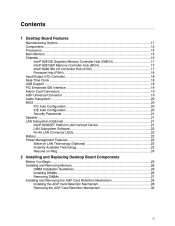
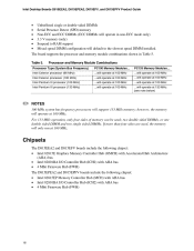
... 2 shows the major components on all the boards. 13 D815EFV and D815EPFV Desktop Board Components ✏ NOTE Components labeled optional do not come on the D815EFV and D815EPFV boards. A B C DE F G H I J EE K DD CC BB AA Z X Y W V U T S R Q P O N L M OM11630 Item Description Item Description A...-style CD-ROM connector Back panel connectors Processor fan connector (fan 1, tach) Digital Video Output (DVO) connector (D815EFV only) • Intel 82815E GMCH (D815EFV only) • Intel 82815EP MCH (D815EPFV only) 370-pin processor socket DIMM sockets Battery Speaker Main power ...
... 2 shows the major components on all the boards. 13 D815EFV and D815EPFV Desktop Board Components ✏ NOTE Components labeled optional do not come on the D815EFV and D815EPFV boards. A B C DE F G H I J EE K DD CC BB AA Z X Y W V U T S R Q P O N L M OM11630 Item Description Item Description A...-style CD-ROM connector Back panel connectors Processor fan connector (fan 1, tach) Digital Video Output (DVO) connector (D815EFV only) • Intel 82815E GMCH (D815EFV only) • Intel 82815EP MCH (D815EPFV only) 370-pin processor socket DIMM sockets Battery Speaker Main power ...

Product Guide
Page 14
... 2. 14 The boards support a single Intel Pentium III processor or Intel Celeron processor above 533 MHz. The processor connects to the Intel desktop board Web site at: http://support.intel.com/support/motherboards/desktop/ For instructions on processor support for theD815EEA2, D815EPEA2, D815EFV, and D815EPFV boards. Processors are not included with the desktop board and must be purchased separately. Table 4. The boards support the processors listed in Table 4. Intel Desktop Boards D815EEA2, D815EPEA2...
... 2. 14 The boards support a single Intel Pentium III processor or Intel Celeron processor above 533 MHz. The processor connects to the Intel desktop board Web site at: http://support.intel.com/support/motherboards/desktop/ For instructions on processor support for theD815EEA2, D815EPEA2, D815EFV, and D815EPFV boards. Processors are not included with the desktop board and must be purchased separately. Table 4. The boards support the processors listed in Table 4. Intel Desktop Boards D815EEA2, D815EPEA2...
Product Guide
Page 16
Intel Desktop Boards D815EEA2, D815EPEA2, D815EFV, and D815EPFV Product Guide Unbuffered single or double-sided DIMMs Serial Presence Detect (SPD) memory Non-ECC and ECC DIMMs (ECC DIMMs will operate in Table 5. The board supports the processor and memory module combinations shown in non-ECC mode only) 3.3 V memory (only) Suspend to the slowest speed DIMM installed. however...
Intel Desktop Boards D815EEA2, D815EPEA2, D815EFV, and D815EPFV Product Guide Unbuffered single or double-sided DIMMs Serial Presence Detect (SPD) memory Non-ECC and ECC DIMMs (ECC DIMMs will operate in Table 5. The board supports the processor and memory module combinations shown in non-ECC mode only) 3.3 V memory (only) Suspend to the slowest speed DIMM installed. however...
Product Guide
Page 19
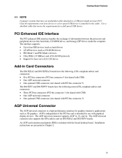
PCI Enhanced IDE Interface The PCI enhanced IDE interface handles the exchange of information between the processor and peripheral devices like hard disks, CD-ROM drives, and Iomega ZIP Use a shielded cable that have an unshielded cable attached to a USB port might not meet FCC Class B requirements even if no device or a low-speed USB device is attached to the cable. Desktop Board Features ✏ NOTE Computer systems that meets the requirements for a full-speed USB device.
PCI Enhanced IDE Interface The PCI enhanced IDE interface handles the exchange of information between the processor and peripheral devices like hard disks, CD-ROM drives, and Iomega ZIP Use a shielded cable that have an unshielded cable attached to a USB port might not meet FCC Class B requirements even if no device or a low-speed USB device is attached to the cable. Desktop Board Features ✏ NOTE Computer systems that meets the requirements for a full-speed USB device.
Product Guide
Page 25
... remove memory Install and remove the AGP card retention mechanism (included) Install and remove AGP and GPA cards Install the I/O shield Install the desktop board Install and remove the processor Replace the battery Connect the IDE cable Set the BIOS configuration jumper Before You Begin ✏ NOTE Before you open the computer or...
... remove memory Install and remove the AGP card retention mechanism (included) Install and remove AGP and GPA cards Install the I/O shield Install the desktop board Install and remove the processor Replace the battery Connect the IDE cable Set the BIOS configuration jumper Before You Begin ✏ NOTE Before you open the computer or...
Product Guide
Page 36
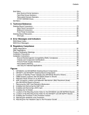
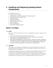
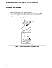
Aligning the pins of the processor with the socket, insert the processor into the socket (see Figure 13, D). Intel Desktop Boards D815EEA2, D815EPEA2, D815EFV, and D815EPFV Product Guide Installing a Processor To install a processor, follow these instructions: 1. Close the handle completely (see Figure 13, A and C). 4. B C A D OM11639 Figure 13. Observe the precautions in the Processor Socket 36 Installing the Processor in "Before You Begin" (see Figure 13, B). 3. Locate the processor socket and raise the socket handle completely (see page 25). 2.
Aligning the pins of the processor with the socket, insert the processor into the socket (see Figure 13, D). Intel Desktop Boards D815EEA2, D815EPEA2, D815EFV, and D815EPFV Product Guide Installing a Processor To install a processor, follow these instructions: 1. Close the handle completely (see Figure 13, A and C). 4. B C A D OM11639 Figure 13. Observe the precautions in the Processor Socket 36 Installing the Processor in "Before You Begin" (see Figure 13, B). 3. Locate the processor socket and raise the socket handle completely (see page 25). 2.

Product Guide
Page 37
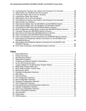
Installing and Replacing Desktop Board Components ✏ NOTE For instructions on top of the processor (see Figure 14). Attaching the Heatsink to install a fan heatsink for a processor 1 GHz or greater, see Figure 15). 0 A B OM11620 A B Fan heatsink clip Processor socket Figure 15. Attach the fan heatsink clips to the Processor Socket 37 Place the fan heatsink on how to the Processor 6. P G A 37 OM11619 Figure 14. Attaching the Fan Heatsink Clips to the processor socket (see page 39. 5.
Installing and Replacing Desktop Board Components ✏ NOTE For instructions on top of the processor (see Figure 14). Attaching the Heatsink to install a fan heatsink for a processor 1 GHz or greater, see Figure 15). 0 A B OM11620 A B Fan heatsink clip Processor socket Figure 15. Attach the fan heatsink clips to the Processor Socket 37 Place the fan heatsink on how to the Processor 6. P G A 37 OM11619 Figure 14. Attaching the Fan Heatsink Clips to the processor socket (see page 39. 5.
Product Guide
Page 38
... 0 OM11156 Figure 16. Observe the precautions in "Before You Begin" (see Figure 16). Disconnect the processor fan cable. 3. Raise the socket handle completely. 6. Intel Desktop Boards D815EEA2, D815EPEA2, D815EFV, and D815EPFV Product Guide 7. Remove the processor. 38 Remove the heatsink. 5. Connect the processor fan cable to the Processor Fan Connector Removing the Processor To remove the processor, follow these instructions: 1.
... 0 OM11156 Figure 16. Observe the precautions in "Before You Begin" (see Figure 16). Disconnect the processor fan cable. 3. Raise the socket handle completely. 6. Intel Desktop Boards D815EEA2, D815EPEA2, D815EFV, and D815EPFV Product Guide 7. Remove the processor. 38 Remove the heatsink. 5. Connect the processor fan cable to the Processor Fan Connector Removing the Processor To remove the processor, follow these instructions: 1.

Product Guide
Page 39
...Desktop Board Components Installing a 1 GHz Processor Fan Heatsink To install a processor, follow the instructions given on the Fan Heatsink 39 Placing the Plastic Clip on page 36, Figure 13. Making sure the handle is aligned on the processor socket label side (see Figure 17, A). Attaching the Fan Heatsink Over the Processor...notch location. Attach the fan heatsink to install the fan heatsink on the fan heatsink (see Figure 18, B) on a processor 1 GHz or greater. 1. The inset in the up position, place the plastic clip (see Figure 18, C). A OM11063 Figure 17....
...Desktop Board Components Installing a 1 GHz Processor Fan Heatsink To install a processor, follow the instructions given on the Fan Heatsink 39 Placing the Plastic Clip on page 36, Figure 13. Making sure the handle is aligned on the processor socket label side (see Figure 17, A). Attaching the Fan Heatsink Over the Processor...notch location. Attach the fan heatsink to install the fan heatsink on the fan heatsink (see Figure 18, B) on a processor 1 GHz or greater. 1. The inset in the up position, place the plastic clip (see Figure 18, C). A OM11063 Figure 17....
Product Guide
Page 40
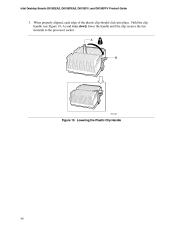
A B OM11062 Figure 19. Lowering the Plastic Clip Handle 40 Intel Desktop Boards D815EEA2, D815EPEA2, D815EFV, and D815EPFV Product Guide 3. When properly aligned, each edge of the plastic clip should click into place. Hold the clip handle (see Figure 19, A) and very slowly lower the handle until the clip secures the fan heatsink to the processor socket.
A B OM11062 Figure 19. Lowering the Plastic Clip Handle 40 Intel Desktop Boards D815EEA2, D815EPEA2, D815EFV, and D815EPFV Product Guide 3. When properly aligned, each edge of the plastic clip should click into place. Hold the clip handle (see Figure 19, A) and very slowly lower the handle until the clip secures the fan heatsink to the processor socket.

Product Guide
Page 41
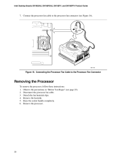
A B C OM11061 Figure 20. Connect the processor fan cable to the Fan Heatsink 5. Clip the fan (A) over the fan heatsink (B) as illustrated in Figure 20. J1B1 J1B1 OM11175 Figure 21. Attaching the Fan to the processor fan connector (see Figure 21). Connecting the Processor Fan Cable to the Processor Fan Connector 41 Installing and Replacing Desktop Board Components 4.
A B C OM11061 Figure 20. Connect the processor fan cable to the Fan Heatsink 5. Clip the fan (A) over the fan heatsink (B) as illustrated in Figure 20. J1B1 J1B1 OM11175 Figure 21. Attaching the Fan to the processor fan connector (see Figure 21). Connecting the Processor Fan Cable to the Processor Fan Connector 41 Installing and Replacing Desktop Board Components 4.
Product Guide
Page 42
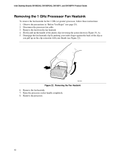
... on the clip extension with your thumb (see page 25). 2. Remove the processor. 42 Intel Desktop Boards D815EEA2, D815EPEA2, D815EFV, and D815EPFV Product Guide Removing the 1 GHz Processor Fan Heatsink To remove the fan heatsink for the 1 GHz (or greater) processor, follow these instructions: 1. Raise the processor socket handle completely. 8. Remove the fan from the fan heatsink. 4. Observe...
... on the clip extension with your thumb (see page 25). 2. Remove the processor. 42 Intel Desktop Boards D815EEA2, D815EPEA2, D815EFV, and D815EPFV Product Guide Removing the 1 GHz Processor Fan Heatsink To remove the fan heatsink for the 1 GHz (or greater) processor, follow these instructions: 1. Raise the processor socket handle completely. 8. Remove the fan from the fan heatsink. 4. Observe...

Product Guide
Page 58
...Key or or Maintenance Menu This menu is used to clear passwords, to access the extended configuration submenu, and to access processor information. Clears the Wired for menu screens. Table 9. Maintenance Main Advanced Security Power Boot Exit Extended Configuration Table 10.... only displays this menu, select Maintenance on the menu bar at the top of the screen. Displays CPU's Microcode Update Revision. Intel Desktop Boards D815EEA2, D815EPEA2, D815EFV, and D815EPFV Product Guide Table 9 shows the function keys available for Management Boot Integrity Service (BIS) credentials....
...Key or or Maintenance Menu This menu is used to clear passwords, to access the extended configuration submenu, and to access processor information. Clears the Wired for menu screens. Table 9. Maintenance Main Advanced Security Power Boot Exit Extended Configuration Table 10.... only displays this menu, select Maintenance on the menu bar at the top of the screen. Displays CPU's Microcode Update Revision. Intel Desktop Boards D815EEA2, D815EPEA2, D815EFV, and D815EPFV Product Guide Table 9 shows the function keys available for Management Boot Integrity Service (BIS) credentials....
Product Guide
Page 59
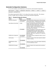
...; 3 • 2 • Auto (default) SDRAM RAS# to Auto or User Defined. Maintenance Main Advanced Security Power Boot Exit Extended Configuration The submenu represented by the processor. This setting identifies the video memory range as uncacheable by Table 11 is selected under Extended Configuration. Well suited for setting video memory cache mode...
...; 3 • 2 • Auto (default) SDRAM RAS# to Auto or User Defined. Maintenance Main Advanced Security Power Boot Exit Extended Configuration The submenu represented by the processor. This setting identifies the video memory range as uncacheable by Table 11 is selected under Extended Configuration. Well suited for setting video memory cache mode...


