
Product Guide
Page 4
Intel Desktop Boards D815EEA2, D815EPEA2, D815EFV, and D815EPFV Product Guide Installing and Removing AGP and GPA Cards ...31 Installing an AGP Card ...31 Removing the AGP Card from the Retention Mechanism ...31 Installing and Removing a GPA Card (D815EEA2 and D815EFV only) ...32 Installing the I/O Shield ...33 Installing the Desktop Board...34 Installing a Processor ...36 Removing the Processor ...38 Installing a 1 GHz Processor Fan...
Intel Desktop Boards D815EEA2, D815EPEA2, D815EFV, and D815EPFV Product Guide Installing and Removing AGP and GPA Cards ...31 Installing an AGP Card ...31 Removing the AGP Card from the Retention Mechanism ...31 Installing and Removing a GPA Card (D815EEA2 and D815EFV only) ...32 Installing the I/O Shield ...33 Installing the Desktop Board...34 Installing a Processor ...36 Removing the Processor ...38 Installing a 1 GHz Processor Fan...
Product Guide
Page 5
D815EEA2 and D815EPEA2 Desktop Board Components...12 D815EFV and D815EPFV Desktop Board Components ...13 Location of Standby Power Indicator (the D815EEA2 Board Is Shown)...24 DIMM Socket Locations (the D815EEA2 Board Is Shown) ...27 Retention Notch Shown on an AGP Card ...28 AGP Connector Location and Retention Mechanism (RM) Placement (Inset) (the D815EEA2 Board... Overload...94 Place Battery Marking ...94 Use Only for the D815EFV and D815EPFV Boards...35 Installing the Processor in the Processor Socket ...36 Attaching the Heatsink to the Processor ...37 Attaching the Fan Heatsink Clips to the...
D815EEA2 and D815EPEA2 Desktop Board Components...12 D815EFV and D815EPFV Desktop Board Components ...13 Location of Standby Power Indicator (the D815EEA2 Board Is Shown)...24 DIMM Socket Locations (the D815EEA2 Board Is Shown) ...27 Retention Notch Shown on an AGP Card ...28 AGP Connector Location and Retention Mechanism (RM) Placement (Inset) (the D815EEA2 Board... Overload...94 Place Battery Marking ...94 Use Only for the D815EFV and D815EPFV Boards...35 Installing the Processor in the Processor Socket ...36 Attaching the Heatsink to the Processor ...37 Attaching the Fan Heatsink Clips to the...
Product Guide
Page 6
...22 Jumper Settings for the D815EFV and D815EPFV Boards...84 33. Add-in Board and Peripheral Interface Connectors for the D815EEA2 and D815EPEA2 Boards ...83 32. Connecting the Processor Fan Cable to the Processor Fan Connector ...38 Attaching the Fan Heatsink Over the Processor ...39 Placing the Plastic Clip on the ... Submenu ...68 Event Log Configuration Submenu ...69 Video Configuration Submenu ...70 Security Menu...71 Power Menu...72 APM Submenu...73 vi Intel Desktop Boards D815EEA2, D815EPEA2, D815EFV, and D815EPFV Product Guide 16. 17. 18. 19. 20. 21. 22. 23. 24. 25. 26. 27. 28. 29...
...22 Jumper Settings for the D815EFV and D815EPFV Boards...84 33. Add-in Board and Peripheral Interface Connectors for the D815EEA2 and D815EPEA2 Boards ...83 32. Connecting the Processor Fan Cable to the Processor Fan Connector ...38 Attaching the Fan Heatsink Over the Processor ...39 Placing the Plastic Clip on the ... Submenu ...68 Event Log Configuration Submenu ...69 Video Configuration Submenu ...70 Security Menu...71 Power Menu...72 APM Submenu...73 vi Intel Desktop Boards D815EEA2, D815EPEA2, D815EFV, and D815EPFV Product Guide 16. 17. 18. 19. 20. 21. 22. 23. 24. 25. 26. 27. 28. 29...

Product Guide
Page 9
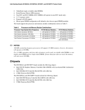
... MHz system bus frequency processors) Chipsets • The D815EEA2 and D815EFV boards include the Intel 815E Chipset, consisting of: Intel 82815E Graphics Memory Controller Hub (GMCH) Intel® 82801BA I/O Controller Hub (ICH2) Characteristic Form Factors 4 Mbit Firmware Hub (FWH) • The D815EPEA2 and D815EPFV boards include the Intel 815EP Chipset, consisting of the boards. 1 Desktop Board Features Table 1 describes...
... MHz system bus frequency processors) Chipsets • The D815EEA2 and D815EFV boards include the Intel 815E Chipset, consisting of: Intel 82815E Graphics Memory Controller Hub (GMCH) Intel® 82801BA I/O Controller Hub (ICH2) Characteristic Form Factors 4 Mbit Firmware Hub (FWH) • The D815EPEA2 and D815EPFV boards include the Intel 815EP Chipset, consisting of the boards. 1 Desktop Board Features Table 1 describes...

Product Guide
Page 12
... boards. 12 D815EEA2 and D815EPEA2 Desktop Board Components ✏ NOTE Components labeled optional do not come on the D815EEA2 and D815EPEA2 boards. AD1885 audio codec AGP universal connector ATAPI-style auxiliary line in connector Front panel audio connector (optional) ATAPI-style CD-ROM connector Back panel connectors Processor fan connector (fan 1, tach) Digital Video Output (DVO) connector (D815EEA2 only) • Intel...
... boards. 12 D815EEA2 and D815EPEA2 Desktop Board Components ✏ NOTE Components labeled optional do not come on the D815EEA2 and D815EPEA2 boards. AD1885 audio codec AGP universal connector ATAPI-style auxiliary line in connector Front panel audio connector (optional) ATAPI-style CD-ROM connector Back panel connectors Processor fan connector (fan 1, tach) Digital Video Output (DVO) connector (D815EEA2 only) • Intel...

Product Guide
Page 14
... III processor or Intel Celeron processor above 533 MHz. Table 4. Intel Desktop Boards D815EEA2, D815EPEA2, D815EFV, and D815EPFV Product Guide Processors CAUTION Use only the processors listed below. See the Intel Desktop D815EA2/D815EPEA2 or D815EFV/D815EPFV Specification Update for the latest list of unsupported processors can damage the board, the processor, and the power supply. The boards support the processors listed in Table 4. Processor Type Intel Pentium III processors Supported Processors...
... III processor or Intel Celeron processor above 533 MHz. Table 4. Intel Desktop Boards D815EEA2, D815EPEA2, D815EFV, and D815EPFV Product Guide Processors CAUTION Use only the processors listed below. See the Intel Desktop D815EA2/D815EPEA2 or D815EFV/D815EPFV Specification Update for the latest list of unsupported processors can damage the board, the processor, and the power supply. The boards support the processors listed in Table 4. Processor Type Intel Pentium III processors Supported Processors...
Product Guide
Page 16
... DIMM and two single sided DIMMs. If more than four sides are used ; The board supports the processor and memory module combinations shown in non-ECC mode only) 3.3 V memory (only) Suspend to the slowest speed DIMM installed. Intel Desktop Boards D815EEA2, D815EPEA2, D815EFV, and D815EPFV Product Guide Unbuffered single or double-sided DIMMs Serial Presence Detect (SPD...
... DIMM and two single sided DIMMs. If more than four sides are used ; The board supports the processor and memory module combinations shown in non-ECC mode only) 3.3 V memory (only) Suspend to the slowest speed DIMM installed. Intel Desktop Boards D815EEA2, D815EPEA2, D815EFV, and D815EPFV Product Guide Unbuffered single or double-sided DIMMs Serial Presence Detect (SPD...
Product Guide
Page 36
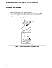
Locate the processor socket and raise the socket handle completely (see Figure 13, A and C). 4. Aligning the pins of the processor with the socket, insert the processor into the socket (see Figure 13, B). 3. B C A D OM11639 Figure 13. Close the handle completely (see page 25). 2. Intel Desktop Boards D815EEA2, D815EPEA2, D815EFV, and D815EPFV Product Guide Installing a Processor To install a processor, follow these instructions: 1. Installing the Processor in "Before You Begin" (see Figure 13, D). Observe the precautions in the Processor Socket 36
Locate the processor socket and raise the socket handle completely (see Figure 13, A and C). 4. Aligning the pins of the processor with the socket, insert the processor into the socket (see Figure 13, B). 3. B C A D OM11639 Figure 13. Close the handle completely (see page 25). 2. Intel Desktop Boards D815EEA2, D815EPEA2, D815EFV, and D815EPFV Product Guide Installing a Processor To install a processor, follow these instructions: 1. Installing the Processor in "Before You Begin" (see Figure 13, D). Observe the precautions in the Processor Socket 36
Product Guide
Page 38
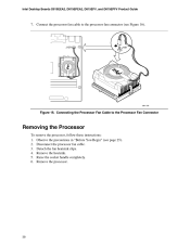
... precautions in "Before You Begin" (see Figure 16). Remove the heatsink. 5. Intel Desktop Boards D815EEA2, D815EPEA2, D815EFV, and D815EPFV Product Guide 7. Connecting the Processor Fan Cable to the processor fan connector (see page 25). 2. Disconnect the processor fan cable. 3. Raise the socket handle completely. 6. Remove the processor. 38 J1B1 J1B1 A PG 37 0 OM11156 Figure 16. Detach the fan heatsink...
... precautions in "Before You Begin" (see Figure 16). Remove the heatsink. 5. Intel Desktop Boards D815EEA2, D815EPEA2, D815EFV, and D815EPFV Product Guide 7. Connecting the Processor Fan Cable to the processor fan connector (see page 25). 2. Disconnect the processor fan cable. 3. Raise the socket handle completely. 6. Remove the processor. 38 J1B1 J1B1 A PG 37 0 OM11156 Figure 16. Detach the fan heatsink...
Product Guide
Page 40
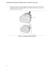
A B OM11062 Figure 19. Lowering the Plastic Clip Handle 40 When properly aligned, each edge of the plastic clip should click into place. Hold the clip handle (see Figure 19, A) and very slowly lower the handle until the clip secures the fan heatsink to the processor socket. Intel Desktop Boards D815EEA2, D815EPEA2, D815EFV, and D815EPFV Product Guide 3.
A B OM11062 Figure 19. Lowering the Plastic Clip Handle 40 When properly aligned, each edge of the plastic clip should click into place. Hold the clip handle (see Figure 19, A) and very slowly lower the handle until the clip secures the fan heatsink to the processor socket. Intel Desktop Boards D815EEA2, D815EPEA2, D815EFV, and D815EPFV Product Guide 3.
Product Guide
Page 42
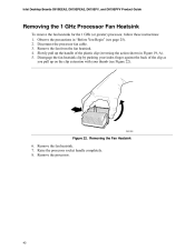
... the fan heatsink clip by pushing your thumb (see page 25). 2. Remove the fan heatsink. 7. Intel Desktop Boards D815EEA2, D815EPEA2, D815EFV, and D815EPFV Product Guide Removing the 1 GHz Processor Fan Heatsink To remove the fan heatsink for the 1 GHz (or greater) processor, follow these instructions: 1. Removing the Fan Heatsink 6. Slowly pull up on the clip extension with...
... the fan heatsink clip by pushing your thumb (see page 25). 2. Remove the fan heatsink. 7. Intel Desktop Boards D815EEA2, D815EPEA2, D815EFV, and D815EPFV Product Guide Removing the 1 GHz Processor Fan Heatsink To remove the fan heatsink for the 1 GHz (or greater) processor, follow these instructions: 1. Removing the Fan Heatsink 6. Slowly pull up on the clip extension with...

Product Guide
Page 58
...default) • No Description Clears the user and administrative passwords. Invokes the Extended Configuration submenu. Displays CPU's Stepping Signature. Intel Desktop Boards D815EEA2, D815EPEA2, D815EFV, and D815EPFV Product Guide Table 9 shows the function keys available for the current menu Save the current values and ...or Maintenance Menu This menu is used to clear passwords, to access the extended configuration submenu, and to access processor information. To access this menu in the configure mode. BIOS Setup Program Function Keys Description Selects a different menu...
...default) • No Description Clears the user and administrative passwords. Invokes the Extended Configuration submenu. Displays CPU's Stepping Signature. Intel Desktop Boards D815EEA2, D815EPEA2, D815EFV, and D815EPFV Product Guide Table 9 shows the function keys available for the current menu Save the current values and ...or Maintenance Menu This menu is used to clear passwords, to access the extended configuration submenu, and to access processor information. To access this menu in the configure mode. BIOS Setup Program Function Keys Description Selects a different menu...

Product Guide
Page 60
... the total amount of RAM in the memory banks. Displays processor speed. Displays the amount and type of RAM. Specifies the current date. 60 Table 12. Displays the system bus frequency. Intel Desktop Boards D815EEA2, D815EPEA2, D815EFV, and D815EPFV Product Guide Main Menu To access this... menu, select Main on the menu bar at the top of the BIOS. Feature BIOS Version Processor Type Processor Speed System Bus Frequency Cache RAM Total ...
... the total amount of RAM in the memory banks. Displays processor speed. Displays the amount and type of RAM. Specifies the current date. 60 Table 12. Displays the system bus frequency. Intel Desktop Boards D815EEA2, D815EPEA2, D815EFV, and D815EPFV Product Guide Main Menu To access this... menu, select Main on the menu bar at the top of the BIOS. Feature BIOS Version Processor Type Processor Speed System Bus Frequency Cache RAM Total ...

Product Guide
Page 82
Power and Hardware Control Connectors (the D815EEA2 Board Is Shown) 82 A 1 2 1 1 7 10 1 1 11 10 20 H GF E Item A B C D E F G H D Description Processor fan (fan 1) Power Chassis fan (fan 3) Front panel USB (optional) SCSI LED Chassis fan (fan 2) Chassis intrusion C B OM11631 Wake on LAN technology (optional) Figure 30. Intel Desktop Boards D815EEA2, D815EPEA2, D815EFV, and D815EPFV Product Guide Power and Hardware Control Connectors Figure 30 shows the power and hardware connectors.
Power and Hardware Control Connectors (the D815EEA2 Board Is Shown) 82 A 1 2 1 1 7 10 1 1 11 10 20 H GF E Item A B C D E F G H D Description Processor fan (fan 1) Power Chassis fan (fan 3) Front panel USB (optional) SCSI LED Chassis fan (fan 2) Chassis intrusion C B OM11631 Wake on LAN technology (optional) Figure 30. Intel Desktop Boards D815EEA2, D815EPEA2, D815EFV, and D815EPFV Product Guide Power and Hardware Control Connectors Figure 30 shows the power and hardware connectors.


