
Product Specification
Page 9
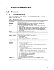
Feature Summary Form Factor Processor Memory Chipset Mini-ITX, (6.7 inches by 6.7 inches [170 millimeters by 170 millimeters]) compatible with microATX Passively-cooled, soldered-down Single-Core Intel® Atom™ processor with integrated graphics and integrated memory controller • Two ... 1066 MHz and DDR3 1333 MHz memory will run at 800 MHz • Support for up to 2 GB of Intel Desktop Board D425KT and Intel Desktop Board D425KTW. Table 1. D425KTW only) Legacy I/O Control Peripheral Interfaces LAN Support Winbond W83627DHG-A based Legacy I/O controller for hardware...
Feature Summary Form Factor Processor Memory Chipset Mini-ITX, (6.7 inches by 6.7 inches [170 millimeters by 170 millimeters]) compatible with microATX Passively-cooled, soldered-down Single-Core Intel® Atom™ processor with integrated graphics and integrated memory controller • Two ... 1066 MHz and DDR3 1333 MHz memory will run at 800 MHz • Support for up to 2 GB of Intel Desktop Board D425KT and Intel Desktop Board D425KTW. Table 1. D425KTW only) Legacy I/O Control Peripheral Interfaces LAN Support Winbond W83627DHG-A based Legacy I/O controller for hardware...

Product Specification
Page 38
Figure 9. Intel Desktop Board D425KT and Intel Desktop Board D425KTW Technical Product Specification 2.2.1.2 I/O Shield The I/O shield provided with the board allows access to all back panel connectors and is compatible with wireless PCI Express Mini Card solutions, the I/O shield also provides pre-cut holes for user installation of up to two external wireless antennas. I /O shield reference diagram. Figure 9 shows an I /O Shield Reference Diagram 38 As an added benefit for system configurations with standard mini-ITX and microATX chassis.
Figure 9. Intel Desktop Board D425KT and Intel Desktop Board D425KTW Technical Product Specification 2.2.1.2 I/O Shield The I/O shield provided with the board allows access to all back panel connectors and is compatible with wireless PCI Express Mini Card solutions, the I/O shield also provides pre-cut holes for user installation of up to two external wireless antennas. I /O shield reference diagram. Figure 9 shows an I /O Shield Reference Diagram 38 As an added benefit for system configurations with standard mini-ITX and microATX chassis.

Product Specification
Page 51
Figure 15 illustrates the mechanical form factor for the board. Location of the I/O connectors and mounting holes are in inches [millimeters]. Figure 15. The outer dimensions are given in compliance with the microATX specification. Board Dimensions 51 Dimensions are 6.7 inches by 6.7 inches [170 millimeters by 170 millimeters]. Technical Reference 2.4 Mechanical Considerations 2.4.1 Form Factor The board is designed to fit into a mini-ITX or microATX form-factor chassis.
Figure 15 illustrates the mechanical form factor for the board. Location of the I/O connectors and mounting holes are in inches [millimeters]. Figure 15. The outer dimensions are given in compliance with the microATX specification. Board Dimensions 51 Dimensions are 6.7 inches by 6.7 inches [170 millimeters by 170 millimeters]. Technical Reference 2.4 Mechanical Considerations 2.4.1 Form Factor The board is designed to fit into a mini-ITX or microATX form-factor chassis.

Product Specification
Page 55
...able to dissipate up to 13 W of heat, leading to high ambient temperature within the chassis. A chassis fan located further away from the board region, i.e., at 50 °C. By using the reference pin fin heatsink, most of where the chassis fan is located, the maximum local ...when airflow direction is an exhaust fan. This board is designed to have local ambient temperature safely below the 50 °C limit. 55 Chassis inlet vents should also provide adequate openings for 3-7 liters volumetric or larger, desktop/tower orientation, mini-ITX and micro-ATX chassis with a chassis fan ...
...able to dissipate up to 13 W of heat, leading to high ambient temperature within the chassis. A chassis fan located further away from the board region, i.e., at 50 °C. By using the reference pin fin heatsink, most of where the chassis fan is located, the maximum local ...when airflow direction is an exhaust fan. This board is designed to have local ambient temperature safely below the 50 °C limit. 55 Chassis inlet vents should also provide adequate openings for 3-7 liters volumetric or larger, desktop/tower orientation, mini-ITX and micro-ATX chassis with a chassis fan ...
Product Guide
Page 9
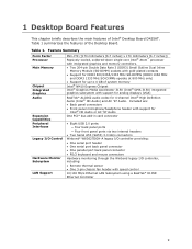
Table 1 summarizes the features of Intel® Desktop Board D425KT. Included are: • Back panel connectors • Front panel microphone/headphone header with support for Intel® HD Audio or AC '97 Audio One PCI* bus add-in card connector •...mouse connectors Hardware monitoring through the Winbond legacy I /O Control Hardware Monitor Subsystem LAN Support Mini-ITX ([170 millimeters [6.7 inches] x 170 millimeters [6.7 inches]) Passively-cooled, soldered-down single-core Intel® Atom™ processor with integrated graphics and memory controllers. • Two 204-...
Table 1 summarizes the features of Intel® Desktop Board D425KT. Included are: • Back panel connectors • Front panel microphone/headphone header with support for Intel® HD Audio or AC '97 Audio One PCI* bus add-in card connector •...mouse connectors Hardware monitoring through the Winbond legacy I /O Control Hardware Monitor Subsystem LAN Support Mini-ITX ([170 millimeters [6.7 inches] x 170 millimeters [6.7 inches]) Passively-cooled, soldered-down single-core Intel® Atom™ processor with integrated graphics and memory controllers. • Two 204-...


