
Technical Product Specification
Page 2
... patent applications, trademarks, copyrights, or other intellectual property rights. Contact your local Intel sales office or your distributor to only the standard Intel NUC Board with BIOS identifier WYLPT10H.86A. and/or other countries. * Other names and brands may ...different processor families: Go to them. Copyright 2013, Intel Corporation. All rights reserved. Intel and Intel Core are not a measure of the Intel NUC Board D54250WYB and Intel NUC Board D34010WYB Technical Product Specification Specification Clarification Date September 2013 October 2013 Disclaimer ...
... patent applications, trademarks, copyrights, or other intellectual property rights. Contact your local Intel sales office or your distributor to only the standard Intel NUC Board with BIOS identifier WYLPT10H.86A. and/or other countries. * Other names and brands may ...different processor families: Go to them. Copyright 2013, Intel Corporation. All rights reserved. Intel and Intel Core are not a measure of the Intel NUC Board D54250WYB and Intel NUC Board D34010WYB Technical Product Specification Specification Clarification Date September 2013 October 2013 Disclaimer ...
Technical Product Specification
Page 3
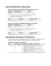
... Clarifications The table below indicates the Specification Changes or Specification Clarifications that apply to show the location of the following component: Device Intel Core i5-4250U Stepping C0 S-Spec Numbers SR16M Basic Intel® NUC Board D34010WYB Identification Information AA Revision BIOS Revision Notes G99257-301 WYLPT10H.86A.0021 1,2 Notes: 1. Board Identification Information Basic...
... Clarifications The table below indicates the Specification Changes or Specification Clarifications that apply to show the location of the following component: Device Intel Core i5-4250U Stepping C0 S-Spec Numbers SR16M Basic Intel® NUC Board D34010WYB Identification Information AA Revision BIOS Revision Notes G99257-301 WYLPT10H.86A.0021 1,2 Notes: 1. Board Identification Information Basic...
Technical Product Specification
Page 5
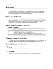
What This Document Contains Chapter 1 2 3 4 5 Description A description of the hardware used on Intel NUC Board D54250WYB and Intel NUC Board D34010WYB A map of the resources of the Intel NUC Board The features supported by the BIOS Setup program A description of the BIOS error messages, beep codes, and POST codes Regulatory compliance and battery disposal information Typographical Conventions...
What This Document Contains Chapter 1 2 3 4 5 Description A description of the hardware used on Intel NUC Board D54250WYB and Intel NUC Board D34010WYB A map of the resources of the Intel NUC Board The features supported by the BIOS Setup program A description of the BIOS error messages, beep codes, and POST codes Regulatory compliance and battery disposal information Typographical Conventions...
Technical Product Specification
Page 8
... D54250WYB and Intel NUC Board D34010WYB Technical Product Specification 2 Technical Reference 2.1 Memory Resources 37 2.1.1 Addressable Memory 37 2.2 Connectors and Headers 37 2.2.1 Front Panel Connectors 38 2.2.2 Back Panel Connectors 38 2.2.3 Header (Top 39 2.2.4 Connectors and Headers (Bottom 40 2.3 BIOS Security Jumper 49 2.4 Mechanical Considerations 51 2.4.1 Form Factor 51 2.5 Electrical Considerations 52 2.5.1 Power Supply Considerations...
... D54250WYB and Intel NUC Board D34010WYB Technical Product Specification 2 Technical Reference 2.1 Memory Resources 37 2.1.1 Addressable Memory 37 2.2 Connectors and Headers 37 2.2.1 Front Panel Connectors 38 2.2.2 Back Panel Connectors 38 2.2.3 Header (Top 39 2.2.4 Connectors and Headers (Bottom 40 2.3 BIOS Security Jumper 49 2.4 Mechanical Considerations 51 2.4.1 Form Factor 51 2.5 Electrical Considerations 52 2.5.1 Power Supply Considerations...

Technical Product Specification
Page 9
... Zones 54 Tables 1. Components Shown in Figure 10 39 ix Audio Formats Supported by the Mini HDMI and Mini DisplayPort Interfaces 24 8. Effects of the BIOS Security Jumper 49 17. Block Diagram 17 4. Power States and Targeted System Power 32 11. Location of Pressing the Power Switch 31 10. Back Panel...
... Zones 54 Tables 1. Components Shown in Figure 10 39 ix Audio Formats Supported by the Mini HDMI and Mini DisplayPort Interfaces 24 8. Effects of the BIOS Security Jumper 49 17. Block Diagram 17 4. Power States and Targeted System Power 32 11. Location of Pressing the Power Switch 31 10. Back Panel...

Technical Product Specification
Page 10
...x Supervisor and User Password Functions 64 31. Front-panel Power LED Blink Codes 65 32. Safety Standards 67 34. States for BIOS Recovery 60 28. EMC Regulations 69 35. Connectors and Headers Shown in Figure 10 41 14. PCI Express Full-/Half-Mini Card... 61 29. Fan Header Current Capability 53 24. Tcontrol Values for Components 55 25. Environmental Specifications 56 27. BIOS Security Jumper Settings 50 23. Master Key and User Hard Drive Password Functions 63 30. Intel NUC Board D54250WYB and Intel NUC Board D34010WYB Technical Product Specification 13.
...x Supervisor and User Password Functions 64 31. Front-panel Power LED Blink Codes 65 32. Safety Standards 67 34. States for BIOS Recovery 60 28. EMC Regulations 69 35. Connectors and Headers Shown in Figure 10 41 14. PCI Express Full-/Half-Mini Card... 61 29. Fan Header Current Capability 53 24. Tcontrol Values for Components 55 25. Environmental Specifications 56 27. BIOS Security Jumper Settings 50 23. Master Key and User Hard Drive Password Functions 63 30. Intel NUC Board D54250WYB and Intel NUC Board D34010WYB Technical Product Specification 13.

Technical Product Specification
Page 12
...D54250WYB and Intel NUC Board D34010WYB Technical Product Specification Table 1. Feature Summary (continued) Expansion Capabilities BIOS Instantly Available PC Technology LAN Support • One PCI Express Half-Mini Card connector • One PCI Express Full-Mini Card connector • Intel® BIOS resident ...in the Serial Peripheral Interface (SPI) Flash device • Support for Advanced Configuration and Power Interface (ACPI), Plug and Play, and System Management BIOS (SMBIOS) • Support for PCI Express*...
...D54250WYB and Intel NUC Board D34010WYB Technical Product Specification Table 1. Feature Summary (continued) Expansion Capabilities BIOS Instantly Available PC Technology LAN Support • One PCI Express Half-Mini Card connector • One PCI Express Full-Mini Card connector • Intel® BIOS resident ...in the Serial Peripheral Interface (SPI) Flash device • Support for Advanced Configuration and Power Interface (ACPI), Plug and Play, and System Management BIOS (SMBIOS) • Support for PCI Express*...
Technical Product Specification
Page 18
... D54250WYB and Intel NUC Board D34010WYB Intel NUC Board Support Available configurations for Intel NUC Board D54250WYB and Intel NUC Board D34010WYB BIOS and driver updates Tested memory Integration information Processor datasheet Visit this World Wide Web site: http://www.intel.com/NUC http://www.intel.com/NUCSupport http://ark.intel.com http://downloadcenter.intel.com http://www.intel.com/NUCSupport http...
... D54250WYB and Intel NUC Board D34010WYB Intel NUC Board Support Available configurations for Intel NUC Board D54250WYB and Intel NUC Board D34010WYB BIOS and driver updates Tested memory Integration information Processor datasheet Visit this World Wide Web site: http://www.intel.com/NUC http://www.intel.com/NUCSupport http://ark.intel.com http://downloadcenter.intel.com http://www.intel.com/NUCSupport http...
Technical Product Specification
Page 19
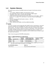
... rows of SDRAM) and "SS" refers to accurately configure memory settings for information on page 37 for optimum performance. This allows the BIOS to read the SPD data and program the chipset to single-sided memory modules (containing one row of addressable memory. • Minimum ...memory settings, but performance and reliability may be populated with 4 Gb memory technology). If non-SPD memory is installed, the BIOS will attempt to : http://www.intel.com/NUCSupport 19 Table 4. Product Description 1.4 System Memory The board has two 204-pin SO-DIMM sockets and support the...
... rows of SDRAM) and "SS" refers to accurately configure memory settings for information on page 37 for optimum performance. This allows the BIOS to read the SPD data and program the chipset to single-sided memory modules (containing one row of addressable memory. • Minimum ...memory settings, but performance and reliability may be populated with 4 Gb memory technology). If non-SPD memory is installed, the BIOS will attempt to : http://www.intel.com/NUCSupport 19 Table 4. Product Description 1.4 System Memory The board has two 204-pin SO-DIMM sockets and support the...
Technical Product Specification
Page 25
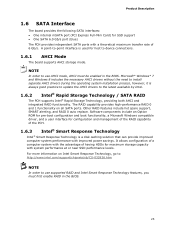
... a Microsoft Windows compatible driver, and a user interface for configuration and management of the RAID capability of the PCH. 1.6.3 Intel® Smart Response Technology Intel® Smart Response Technology is used for maximum storage capacity with system performance at or near SSD performance levels. The RAID ...process, however, it is always good practice to update the AHCI drivers to use AHCI mode, AHCI must first enable RAID in the BIOS. NOTE In order to device connections. 1.6.1 AHCI Mode The board supports AHCI storage mode. For more information on all SATA ports. ...
... a Microsoft Windows compatible driver, and a user interface for configuration and management of the RAID capability of the PCH. 1.6.3 Intel® Smart Response Technology Intel® Smart Response Technology is used for maximum storage capacity with system performance at or near SSD performance levels. The RAID ...process, however, it is always good practice to update the AHCI drivers to use AHCI mode, AHCI must first enable RAID in the BIOS. NOTE In order to device connections. 1.6.1 AHCI Mode The board supports AHCI storage mode. For more information on all SATA ports. ...
Technical Product Specification
Page 26
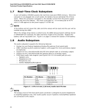
...header), with an equivalent one. When the computer is accurate to power headphones or amplified speakers only. Intel NUC Board D54250WYB and Intel NUC Board D34010WYB Technical Product Specification 1.7 Real-Time Clock Subsystem A coin-cell battery (CR2032) powers the real-time ...clock and CMOS memory. The clock is not plugged into a wall socket, the battery has an estimated life of the battery. When the voltage drops below a certain level, the BIOS...
...header), with an equivalent one. When the computer is accurate to power headphones or amplified speakers only. Intel NUC Board D54250WYB and Intel NUC Board D34010WYB Technical Product Specification 1.7 Real-Time Clock Subsystem A coin-cell battery (CR2032) powers the real-time ...clock and CMOS memory. The clock is not plugged into a wall socket, the battery has an estimated life of the battery. When the voltage drops below a certain level, the BIOS...
Technical Product Specification
Page 34
...from USB requires the use of Instantly Available PC technology requires operating system support and drivers for any installed PCI Express add-in the BIOS Setup program's Boot menu. The computer's response can wake the computer from an ACPI S3 state. The use of a USB ...PC Technology Instantly Available PC technology enables the board to be set in the BIOS, the computer will appear to enter the ACPI S3 (Suspend-toRAM) sleep-state. Intel NUC Board D54250WYB and Intel NUC Board D34010WYB Technical Product Specification 1.11.2.1 Power Input When resuming from an ACPI S5 state...
...from USB requires the use of Instantly Available PC technology requires operating system support and drivers for any installed PCI Express add-in the BIOS Setup program's Boot menu. The computer's response can wake the computer from an ACPI S3 state. The use of a USB ...PC Technology Instantly Available PC technology enables the board to be set in the BIOS, the computer will appear to enter the ACPI S3 (Suspend-toRAM) sleep-state. Intel NUC Board D54250WYB and Intel NUC Board D34010WYB Technical Product Specification 1.11.2.1 Power Input When resuming from an ACPI S5 state...
Technical Product Specification
Page 37
...add-in cards (256 MB) The board provides the capability to the computer's chassis. A fault in cards, PCI Express configuration space, BIOS (SPI Flash device), and chipset overhead resides above the 4 GB boundary. Furthermore, improper connection of DRAM (total system memory). 2 Technical... Reference 2.1 Memory Resources 2.1.1 Addressable Memory The board utilizes 32 GB of system addresses. 2.2 Connectors and Headers CAUTION Only the following : • BIOS/SPI Flash device (96 Mb) • Local APIC (19 MB) • Direct Media Interface (40 MB) • PCI Express configuration space...
...add-in cards (256 MB) The board provides the capability to the computer's chassis. A fault in cards, PCI Express configuration space, BIOS (SPI Flash device), and chipset overhead resides above the 4 GB boundary. Furthermore, improper connection of DRAM (total system memory). 2 Technical... Reference 2.1 Memory Resources 2.1.1 Addressable Memory The board utilizes 32 GB of system addresses. 2.2 Connectors and Headers CAUTION Only the following : • BIOS/SPI Flash device (96 Mb) • Local APIC (19 MB) • Direct Media Interface (40 MB) • PCI Express configuration space...

Technical Product Specification
Page 41
Technical Reference Table 13 lists the connectors and headers identified in Figure 10 Item from Figure 10 Description A PCI Express Full-Mini Card connector B PCI Express Half-Mini Card connector C SATA 6.0 Gb/s connector through the PCH D Front panel dual-port USB 2.0 header (2.0 mm pitch) E Front panel header (2.0 mm pitch) F SATA power connector G BIOS setup configuration jumper H Internal DC power connector 41 Connectors and Headers Shown in Figure 10. Table 13.
Technical Reference Table 13 lists the connectors and headers identified in Figure 10 Item from Figure 10 Description A PCI Express Full-Mini Card connector B PCI Express Half-Mini Card connector C SATA 6.0 Gb/s connector through the PCH D Front panel dual-port USB 2.0 header (2.0 mm pitch) E Front panel header (2.0 mm pitch) F SATA power connector G BIOS setup configuration jumper H Internal DC power connector 41 Connectors and Headers Shown in Figure 10. Table 13.

Technical Product Specification
Page 46
...patterns may be connected to provide a visual indicator that is default - Table 21 shows the possible LED states. Intel NUC Board D54250WYB and Intel NUC Board D34010WYB Technical Product Specification Figure 13. States for Front Panel Header (2.0 mm Pitch) 2.2.4.4.1 Hard Drive Activity LED Header Pins... 1 and 3 can be set via BIOS setup. 46 or two-color LED. Connection Diagram for a One-...
...patterns may be connected to provide a visual indicator that is default - Table 21 shows the possible LED states. Intel NUC Board D54250WYB and Intel NUC Board D34010WYB Technical Product Specification Figure 13. States for Front Panel Header (2.0 mm Pitch) 2.2.4.4.1 Hard Drive Activity LED Header Pins... 1 and 3 can be set via BIOS setup. 46 or two-color LED. Connection Diagram for a One-...

Technical Product Specification
Page 47
... want to write their own applications leveraging this header for direct connection to a front panel push-button to trigger a Windows command. Intel will recognize another on/off signal. 2.2.4.5 System ID / Custom Solutions Header (2.0 mm Pitch) The System ID / Customs Solution header...The time requirement is amplified by the operating system. Technical Reference 2.2.4.4.4 Power Switch Header Pins 6 and 8 can be adding BIOS support and accompanying Windows utility to enable Direct Application Launch* feature. General information about Direct Application Launch can be used to monitor...
... want to write their own applications leveraging this header for direct connection to a front panel push-button to trigger a Windows command. Intel will recognize another on/off signal. 2.2.4.5 System ID / Custom Solutions Header (2.0 mm Pitch) The System ID / Customs Solution header...The time requirement is amplified by the operating system. Technical Reference 2.2.4.4.4 Power Switch Header Pins 6 and 8 can be adding BIOS support and accompanying Windows utility to enable Direct Application Launch* feature. General information about Direct Application Launch can be used to monitor...

Technical Product Specification
Page 49
Figure 16. Figure 13 shows the location of the BIOS Security Jumper 49 Otherwise, the board could be damaged. The 3-pin jumper determines the BIOS Security program's mode. Table 22 describes the jumper settings for the three modes: normal, lockdown, and configuration. Location of the BIOS Security Jumper. Technical Reference 2.3 BIOS Security Jumper CAUTION Do not move a jumper with the power on. Always turn off the power and unplug the power cord from the computer before changing a jumper setting.
Figure 16. Figure 13 shows the location of the BIOS Security Jumper 49 Otherwise, the board could be damaged. The 3-pin jumper determines the BIOS Security program's mode. Table 22 describes the jumper settings for the three modes: normal, lockdown, and configuration. Location of the BIOS Security Jumper. Technical Reference 2.3 BIOS Security Jumper CAUTION Do not move a jumper with the power on. Always turn off the power and unplug the power cord from the computer before changing a jumper setting.

Technical Product Specification
Page 50
... was not found, a Config Menu will be cancelled by the Power Button Menu selections): [1] Suppress this menu until the BIOS Security Jumper is found. Intel NUC Board D54250WYB and Intel NUC Board D34010WYB Technical Product Specification Table 22 lists the settings for booting. Table 22. For example, F2 for Setup, F10 for automatic Recovery...
... was not found, a Config Menu will be cancelled by the Power Button Menu selections): [1] Suppress this menu until the BIOS Security Jumper is found. Intel NUC Board D54250WYB and Intel NUC Board D34010WYB Technical Product Specification Table 22 lists the settings for booting. Table 22. For example, F2 for Setup, F10 for automatic Recovery...

Technical Product Specification
Page 55
... operating limit when monitoring this thermal sensor is dissipating less than TDP, the case temperature should be dissipated by embedded thermal sensors in the system BIOS is maintained at the geometric center of the component corresponds to Case Temperature. When the component is Tcontrol. Tcontrol Values for Components Component Tcontrol Processor...
... operating limit when monitoring this thermal sensor is dissipating less than TDP, the case temperature should be dissipated by embedded thermal sensors in the system BIOS is maintained at the geometric center of the component corresponds to Case Temperature. When the component is Tcontrol. Tcontrol Values for Components Component Tcontrol Processor...

Technical Product Specification
Page 57
... program, POST, the PCI auto-configuration utility, LAN EEPROM information, and Plug and Play support. The BIOS displays a message during POST identifying the type of BIOS Features 3.1 Introduction The board uses a Intel Visual BIOS that is stored in the Serial Peripheral Interface Flash Memory (SPI Flash) and can be updated using a disk-based program...
... program, POST, the PCI auto-configuration utility, LAN EEPROM information, and Plug and Play support. The BIOS displays a message during POST identifying the type of BIOS Features 3.1 Introduction The board uses a Intel Visual BIOS that is stored in the Serial Peripheral Interface Flash Memory (SPI Flash) and can be updated using a disk-based program...


