
Technical Product Specification
Page 2
... subject matter. Contact your local Intel sales office or your distributor to only the standard Intel® Next Unit of Computing Board with BIOS identifier GKPPT10H.86A. UNLESS OTHERWISE AGREED IN WRITING BY INTEL, THE INTEL PRODUCTS ARE NOT DESIGNED NOR INTENDED...incompatibilities arising from published specifications. Revision History Revision 001 002 Revision History First release of the Intel® Next Unit of Computing Board D33217GKE Technical Product Specification Specification Clarification Date October 2012 October 2012 Disclaimer This product specification applies to ...
... subject matter. Contact your local Intel sales office or your distributor to only the standard Intel® Next Unit of Computing Board with BIOS identifier GKPPT10H.86A. UNLESS OTHERWISE AGREED IN WRITING BY INTEL, THE INTEL PRODUCTS ARE NOT DESIGNED NOR INTENDED...incompatibilities arising from published specifications. Revision History Revision 001 002 Revision History First release of the Intel® Next Unit of Computing Board D33217GKE Technical Product Specification Specification Clarification Date October 2012 October 2012 Disclaimer This product specification applies to ...
Technical Product Specification
Page 3
... documentation. Board Identification Information Basic Intel® Next Unit of Changes or Clarifications October 2012 Spec Change Added Note to the Intel® Desktop Board D33217GKE. The AA number is found ...on a small label on this AA revision consists of the board. 2. iii Errata Current characterized errata, if any, are documented in a separate Specification Update. Table 1. Specification Changes or Clarifications Date Type of Change Description of Computing Board D33217GKE Identification Information AA Revision BIOS...
... documentation. Board Identification Information Basic Intel® Next Unit of Changes or Clarifications October 2012 Spec Change Added Note to the Intel® Desktop Board D33217GKE. The AA number is found ...on a small label on this AA revision consists of the board. 2. iii Errata Current characterized errata, if any, are documented in a separate Specification Update. Table 1. Specification Changes or Clarifications Date Type of Change Description of Computing Board D33217GKE Identification Information AA Revision BIOS...
Technical Product Specification
Page 5
... is intended to provide detailed, technical information about the conventions used on Intel Next Unit of Computing Board D33217GKE A map of the resources of the Intel Next Unit of Computing Board The features supported by the BIOS Setup program A description of the BIOS error messages, beep codes, and POST codes Regulatory compliance and battery disposal...
... is intended to provide detailed, technical information about the conventions used on Intel Next Unit of Computing Board D33217GKE A map of the resources of the Intel Next Unit of Computing Board The features supported by the BIOS Setup program A description of the BIOS error messages, beep codes, and POST codes Regulatory compliance and battery disposal...

Technical Product Specification
Page 8
Intel Desktop Board D33217GKE Technical Product Specification 2 Technical Reference 2.1 Memory Resources 35 2.1.1 Addressable Memory 35 2.1.2 Memory Map 37 2.2 Connectors and Headers 37 2.2.1 Back Panel Connectors 38 2.2.2 Connectors and Headers (Bottom 39 2.3 BIOS Setup Configuration Jumper 46 2.4 Mechanical Considerations 48 2.4.1 Form Factor 48 2.5 Electrical Considerations 49 2.5.1 Power Supply Considerations 49 2.5.2 Fan Header Current Capability 50...
Intel Desktop Board D33217GKE Technical Product Specification 2 Technical Reference 2.1 Memory Resources 35 2.1.1 Addressable Memory 35 2.1.2 Memory Map 37 2.2 Connectors and Headers 37 2.2.1 Back Panel Connectors 38 2.2.2 Connectors and Headers (Bottom 39 2.3 BIOS Setup Configuration Jumper 46 2.4 Mechanical Considerations 48 2.4.1 Form Factor 48 2.5 Electrical Considerations 49 2.5.1 Power Supply Considerations 49 2.5.2 Fan Header Current Capability 50...
Technical Product Specification
Page 9
Major Board Components (Bottom 15 3. Thermal Solution and Fan Header 29 7. Location of the BIOS Configuration Setup Jumper 46 14. Back Panel Connectors 38 10. Contents 5.1.5 ENERGY STAR* 5.2, e-Standby, and ErP Compliance 78 5.1.6 Regulatory Compliance Marks (Board Level 79 5.2 Battery ...
Major Board Components (Bottom 15 3. Thermal Solution and Fan Header 29 7. Location of the BIOS Configuration Setup Jumper 46 14. Back Panel Connectors 38 10. Contents 5.1.5 ENERGY STAR* 5.2, e-Standby, and ErP Compliance 78 5.1.6 Regulatory Compliance Marks (Board Level 79 5.2 Battery ...

Technical Product Specification
Page 10
... 79 x Feature Summary 11 2. System Memory Map 37 10. Tcontrol Values for BIOS Recovery 58 22. BIOS Error Messages 63 27. Port 80h POST Code Ranges 64 28. Intel Desktop Board D33217GKE Technical Product Specification Tables 1. Components Shown in Figure 10 40 11. Effects of Pressing...for Components 52 19. Safety Standards 71 31. Components Shown in Figure 1 14 3. Power States and Targeted System Power 31 8. BIOS Setup Configuration Jumper Settings 47 17. Thermal Considerations for a One-Color Power LED 44 16. Fan Header Current Capability 50 18. Front...
... 79 x Feature Summary 11 2. System Memory Map 37 10. Tcontrol Values for BIOS Recovery 58 22. BIOS Error Messages 63 27. Port 80h POST Code Ranges 64 28. Intel Desktop Board D33217GKE Technical Product Specification Tables 1. Components Shown in Figure 10 40 11. Effects of Pressing...for Components 52 19. Safety Standards 71 31. Components Shown in Figure 1 14 3. Power States and Targeted System Power 31 8. BIOS Setup Configuration Jumper Settings 47 17. Thermal Considerations for a One-Color Power LED 44 16. Fan Header Current Capability 50 18. Front...
Technical Product Specification
Page 11
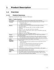
...Support for Advanced Configuration and Power Interface (ACPI), Plug and Play, and System Management BIOS (SMBIOS) continued 11 Table 2. 1 Product Description 1.1 Overview 1.1.1 Feature Summary Table 2 summarizes the major features of the Intel® QS77 Express Platform Controller Hub (PCH) • Integrated graphics support for processors...support • One PCI Express Half-Mini Card connector • One PCI Express Full-Mini Card connector • Intel® BIOS resident in the Serial Peripheral Interface (SPI) Flash device • Support for 1.35 V low voltage JEDEC memory...
...Support for Advanced Configuration and Power Interface (ACPI), Plug and Play, and System Management BIOS (SMBIOS) continued 11 Table 2. 1 Product Description 1.1 Overview 1.1.1 Feature Summary Table 2 summarizes the major features of the Intel® QS77 Express Platform Controller Hub (PCH) • Integrated graphics support for processors...support • One PCI Express Half-Mini Card connector • One PCI Express Full-Mini Card connector • Intel® BIOS resident in the Serial Peripheral Interface (SPI) Flash device • Support for 1.35 V low voltage JEDEC memory...
Technical Product Specification
Page 18
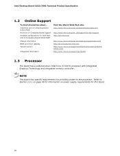
Refer to the processor. Intel Next Unit of Computing Board D33217GKE Next Unit of Computing Board Support Available configurations for this World Wide Web site: http://www.intel.com/products/motherboard/index.htm http://www.intel.com/p/en_US/support?iid=hdr+support http://ark.intel.com Chipset information BIOS and driver updates Tested memory Integration information http...
Refer to the processor. Intel Next Unit of Computing Board D33217GKE Next Unit of Computing Board Support Available configurations for this World Wide Web site: http://www.intel.com/products/motherboard/index.htm http://www.intel.com/p/en_US/support?iid=hdr+support http://ark.intel.com Chipset information BIOS and driver updates Tested memory Integration information http...
Technical Product Specification
Page 19
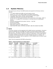
Table 5. Table 5 lists the supported SO-DIMM configurations. If non-SPD memory is installed, the BIOS will attempt to correctly configure the memory settings, but performance and reliability may be populated with 4 Gb memory technology). Supported Memory Configurations Raw ...applicable DDR SDRAM memory specifications, the board should be impacted or the SO-DIMMs may not function under the determined frequency. This allows the BIOS to read the SPD data and program the chipset to accurately configure memory settings for information on availability and are subject to Section 2.1.1 on...
Table 5. Table 5 lists the supported SO-DIMM configurations. If non-SPD memory is installed, the BIOS will attempt to correctly configure the memory settings, but performance and reliability may be populated with 4 Gb memory technology). Supported Memory Configurations Raw ...applicable DDR SDRAM memory specifications, the board should be impacted or the SO-DIMMs may not function under the determined frequency. This allows the BIOS to read the SPD data and program the chipset to accurately configure memory settings for information on availability and are subject to Section 2.1.1 on...
Technical Product Specification
Page 24
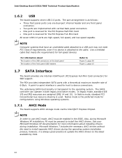
...it is as follows: • Three front panel ports (via the Intel QS77 Express Chipset. Intel Desktop Board D33217GKE Technical Product Specification 1.6.2 USB The board supports seven USB 2.0 ports. The SATA controller can operate in the BIOS. The port arrangement is always good practice to update the AHCI drivers ... • One port is reserved for the PCI Express Half-Mini Card • One port is transparent to the latest available by Intel. 24 NOTE Computer systems that meets the requirements for SSD support. Use a shielded cable that have an unshielded cable attached to a ...
...it is as follows: • Three front panel ports (via the Intel QS77 Express Chipset. Intel Desktop Board D33217GKE Technical Product Specification 1.6.2 USB The board supports seven USB 2.0 ports. The SATA controller can operate in the BIOS. The port arrangement is always good practice to update the AHCI drivers ... • One port is reserved for the PCI Express Half-Mini Card • One port is transparent to the latest available by Intel. 24 NOTE Computer systems that meets the requirements for SSD support. Use a shielded cable that have an unshielded cable attached to a ...
Technical Product Specification
Page 25
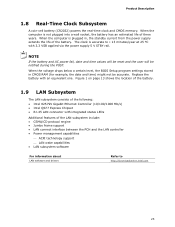
...Clock Subsystem A coin-cell battery (CR2032) powers the real-time clock and CMOS memory. When the voltage drops below a certain level, the BIOS Setup program settings stored in , the standby current from the power supply extends the life of the LAN subsystem include: • CSMA/CD ... 13 shows the location of the battery. 1.9 LAN Subsystem The LAN subsystem consists of the following: • Intel 82579V Gigabit Ethernet Controller (10/100/1000 Mb/s) • Intel QS77 Express Chipset • RJ-45 LAN connector with integrated status LEDs Additional features of the battery. When the...
...Clock Subsystem A coin-cell battery (CR2032) powers the real-time clock and CMOS memory. When the voltage drops below a certain level, the BIOS Setup program settings stored in , the standby current from the power supply extends the life of the LAN subsystem include: • CSMA/CD ... 13 shows the location of the battery. 1.9 LAN Subsystem The LAN subsystem consists of the following: • Intel 82579V Gigabit Ethernet Controller (10/100/1000 Mb/s) • Intel QS77 Express Chipset • RJ-45 LAN connector with integrated status LEDs Additional features of the battery. When the...
Technical Product Specification
Page 33
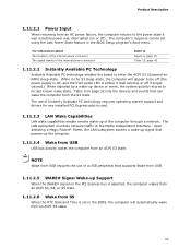
... events that can be off (the power supply is off, and the front panel LED is set using the Last Power State feature in the BIOS Setup program's Boot menu. The computer's response can wake the computer from an ACPI S3 state. The LAN subsystem monitors network traffic at the Media....2.1 Power Input When resuming from an ACPI S5 state. 33 While in the S3 sleep-state, the computer will appear to be set in the BIOS, the computer will automatically wake from an AC power failure, the computer returns to the power state it was in card. 1.11.2.3 LAN Wake Capabilities...
... events that can be off (the power supply is off, and the front panel LED is set using the Last Power State feature in the BIOS Setup program's Boot menu. The computer's response can wake the computer from an ACPI S3 state. The LAN subsystem monitors network traffic at the Media....2.1 Power Input When resuming from an ACPI S5 state. 33 While in the S3 sleep-state, the computer will appear to be set in the BIOS, the computer will automatically wake from an AC power failure, the computer returns to the power state it was in card. 1.11.2.3 LAN Wake Capabilities...
Technical Product Specification
Page 35
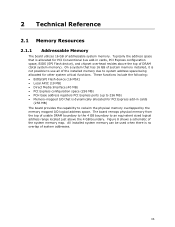
...overlap of the system memory map. The board remaps physical memory from the top of addressable system memory. These functions include the following: • BIOS/SPI Flash device (16 Mbit) • Local APIC (19 MB) • Direct Media Interface (40 MB) • PCI Express configuration...all of DRAM (total system memory). On a system that is allocated for PCI Conventional bus add-in cards, PCI Express configuration space, BIOS (SPI Flash device), and chipset overhead resides above the 4 GB boundary. 2 Technical Reference 2.1 Memory Resources 2.1.1 Addressable Memory The board utilizes...
...overlap of the system memory map. The board remaps physical memory from the top of addressable system memory. These functions include the following: • BIOS/SPI Flash device (16 Mbit) • Local APIC (19 MB) • Direct Media Interface (40 MB) • PCI Express configuration...all of DRAM (total system memory). On a system that is allocated for PCI Conventional bus add-in cards, PCI Express configuration space, BIOS (SPI Flash device), and chipset overhead resides above the 4 GB boundary. 2 Technical Reference 2.1 Memory Resources 2.1.1 Addressable Memory The board utilizes...

Technical Product Specification
Page 37
... memory Conventional memory 2.2 Connectors and Headers CAUTION Only the following connectors and headers have overcurrent protection: back panel and front panel USB. Video memory and BIOS Extended BIOS data (movable by the external devices could cause damage to the board. DFFFF 640 K - 800 K 639 K - 640 K 512 K - 639 K 0... 9FBFF 00000 - 7FFFF Size 16382 MB 64 KB 64 KB 96 KB 160 KB 1 KB 127 KB 512 KB Description Extended memory Runtime BIOS Reserved Potential available high DOS memory (open to devices inside the computer's chassis, such as fans and internal peripherals. FFFFF 896 K - ...
... memory Conventional memory 2.2 Connectors and Headers CAUTION Only the following connectors and headers have overcurrent protection: back panel and front panel USB. Video memory and BIOS Extended BIOS data (movable by the external devices could cause damage to the board. DFFFF 640 K - 800 K 639 K - 640 K 512 K - 639 K 0... 9FBFF 00000 - 7FFFF Size 16382 MB 64 KB 64 KB 96 KB 160 KB 1 KB 127 KB 512 KB Description Extended memory Runtime BIOS Reserved Potential available high DOS memory (open to devices inside the computer's chassis, such as fans and internal peripherals. FFFFF 896 K - ...
Technical Product Specification
Page 44
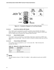
When the switch is normally open. Intel Desktop Board D33217GKE Technical Product Specification Figure 11. Connection Diagram for a One-Color Power LED LED State Description Off Power off Blinking Standby Steady Normal operation NOTE The ... LED to provide a visual indicator that is closed, the board resets and runs the POST. 2.2.2.4.3 Power/Sleep LED Header Pins 2 and 4 can be set via BIOS setup. 44 Proper LED function requires a SATA hard drive or optical drive connected to an onboard SATA connector. 2.2.2.4.2 Reset Switch Header Pins 5 and 7 can be...
When the switch is normally open. Intel Desktop Board D33217GKE Technical Product Specification Figure 11. Connection Diagram for a One-Color Power LED LED State Description Off Power off Blinking Standby Steady Normal operation NOTE The ... LED to provide a visual indicator that is closed, the board resets and runs the POST. 2.2.2.4.3 Power/Sleep LED Header Pins 2 and 4 can be set via BIOS setup. 44 Proper LED function requires a SATA hard drive or optical drive connected to an onboard SATA connector. 2.2.2.4.2 Reset Switch Header Pins 5 and 7 can be...
Technical Product Specification
Page 46
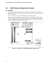
... reports if the two match. Figure 13. Figure 13 shows the location of the BIOS Configuration Setup Jumper 46 Location of the BIOS Setup Configuration jumper. Intel Desktop Board D33217GKE Technical Product Specification 2.3 BIOS Setup Configuration Jumper CAUTION Do not move a jumper with the power on. Always turn off the power and unplug the power...
... reports if the two match. Figure 13. Figure 13 shows the location of the BIOS Configuration Setup Jumper 46 Location of the BIOS Setup Configuration jumper. Intel Desktop Board D33217GKE Technical Product Specification 2.3 BIOS Setup Configuration Jumper CAUTION Do not move a jumper with the power on. Always turn off the power and unplug the power...
Technical Product Specification
Page 47
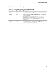
... required. 47 Table 17. Technical Reference Table 17 lists the settings for booting. Recovery None The BIOS attempts to their default values. BIOS Setup Configuration Jumper Settings Function/Mode Normal Configure Jumper Setting 1-2 2-3 Configuration The BIOS uses current configuration information and passwords for the jumper. After the POST runs, Setup runs automatically. Press...
... required. 47 Table 17. Technical Reference Table 17 lists the settings for booting. Recovery None The BIOS attempts to their default values. BIOS Setup Configuration Jumper Settings Function/Mode Normal Configure Jumper Setting 1-2 2-3 Configuration The BIOS uses current configuration information and passwords for the jumper. After the POST runs, Setup runs automatically. Press...
Technical Product Specification
Page 52
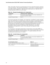
...considering proper airflow to Section 1.2, page 18 http://www.intel.com/Products/Desktop/ Chipsets/ec-QS77/QS77technicaldocuments.htm 52 Thermal Considerations for Components Component Maximum Case Temperature Processor Intel QS77 Express Chipset For processor case temperature, see processor ... limit when monitoring this thermal sensor is Tcontrol. Intel Desktop Board D33217GKE Technical Product Specification Table 19 provides maximum case temperatures for the components that the temperature measurement in the system BIOS is a value reported by the components). The operating...
...considering proper airflow to Section 1.2, page 18 http://www.intel.com/Products/Desktop/ Chipsets/ec-QS77/QS77technicaldocuments.htm 52 Thermal Considerations for Components Component Maximum Case Temperature Processor Intel QS77 Express Chipset For processor case temperature, see processor ... limit when monitoring this thermal sensor is Tcontrol. Intel Desktop Board D33217GKE Technical Product Specification Table 19 provides maximum case temperatures for the components that the temperature measurement in the system BIOS is a value reported by the components). The operating...
Technical Product Specification
Page 55
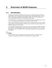
... shows how to view and change the BIOS settings for the computer. The BIOS displays a message during POST identifying the type of BIOS Features 3.1 Introduction The board uses a Intel Visual BIOS that is stored in configure mode. 3 Overview of BIOS and a revision code. The SPI Flash contains the Visual BIOS Setup program, POST, the PCI auto-configuration...
... shows how to view and change the BIOS settings for the computer. The BIOS displays a message during POST identifying the type of BIOS Features 3.1 Introduction The board uses a Intel Visual BIOS that is stored in configure mode. 3 Overview of BIOS and a revision code. The SPI Flash contains the Visual BIOS Setup program, POST, the PCI auto-configuration...
Technical Product Specification
Page 56
... disabled. 2. Legacy USB support operates as event detection and error logging Non-Plug and Play operating systems require an additional interface for system components. Intel Desktop Board D33217GKE Technical Product Specification 3.2 BIOS Flash Memory Organization The Serial Peripheral Interface Flash Memory (SPI Flash) includes a 64 Mb (8192 KB) flash memory device. 3.3 System Management...
... disabled. 2. Legacy USB support operates as event detection and error logging Non-Plug and Play operating systems require an additional interface for system components. Intel Desktop Board D33217GKE Technical Product Specification 3.2 BIOS Flash Memory Organization The Serial Peripheral Interface Flash Memory (SPI Flash) includes a 64 Mb (8192 KB) flash memory device. 3.3 System Management...


