
Technical product specification
Page 7
... 13 1.1.3 Block Diagram 15 1.2 Online Support 16 1.3 Processor 16 1.3.1 Intel® D2550 Graphics Subsystem 17 1.4 System Memory 18 1.5 Intel® NM10 Express Chipset 20 1.5.2 USB 22 1.5.3 SATA Support 22 1.6 Real-Time Clock Subsystem 23 1.7 Legacy I/O Controller 23 1.8 LAN Subsystem 24 1.8.1 LAN Subsystem Drivers 24 1.8.2 RJ-45 LAN Connector with Integrated LEDs 25 1.9 Audio...
... 13 1.1.3 Block Diagram 15 1.2 Online Support 16 1.3 Processor 16 1.3.1 Intel® D2550 Graphics Subsystem 17 1.4 System Memory 18 1.5 Intel® NM10 Express Chipset 20 1.5.2 USB 22 1.5.3 SATA Support 22 1.6 Real-Time Clock Subsystem 23 1.7 Legacy I/O Controller 23 1.8 LAN Subsystem 24 1.8.1 LAN Subsystem Drivers 24 1.8.2 RJ-45 LAN Connector with Integrated LEDs 25 1.9 Audio...

Technical product specification
Page 16
... are recommended above the processor heatsink area for the Intel http://ark.intel.com Desktop Board D2550MUD2 Supported processors Chipset information BIOS and driver updates Tested memory Integration information http://processormatch.intel.com http://www.intel.com/products/desktop/chipsets/index.htm http://downloadcenter.intel.com http://www.intel.com/support/motherboards/desktop/sb/CS025414.htm http://www...
... are recommended above the processor heatsink area for the Intel http://ark.intel.com Desktop Board D2550MUD2 Supported processors Chipset information BIOS and driver updates Tested memory Integration information http://processormatch.intel.com http://www.intel.com/products/desktop/chipsets/index.htm http://downloadcenter.intel.com http://www.intel.com/support/motherboards/desktop/sb/CS025414.htm http://www...

Technical product specification
Page 22
Internal flat panel display settings will not be overwritten by default. 2. and EHCI-compatible drivers (four ports routed to the back panel and three ports routed to seven USB 2.0 ports, supports UHCI and EHCI, and uses UHCI- One...configuration and two devices on the back panel The location of the front panel USB headers (brown-colored) supports an Intel Z-U130 USB Solid-State Drive or compatible device. Intel Desktop Board D2550MUD2 Technical Product Specification NOTE Support for flat panel display configuration complies with a theoretical maximum transfer rate of 3.0 Gb/s ...
Internal flat panel display settings will not be overwritten by default. 2. and EHCI-compatible drivers (four ports routed to the back panel and three ports routed to seven USB 2.0 ports, supports UHCI and EHCI, and uses UHCI- One...configuration and two devices on the back panel The location of the front panel USB headers (brown-colored) supports an Intel Z-U130 USB Solid-State Drive or compatible device. Intel Desktop Board D2550MUD2 Technical Product Specification NOTE Support for flat panel display configuration complies with a theoretical maximum transfer rate of 3.0 Gb/s ...
Technical product specification
Page 23
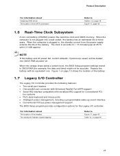
For information about Obtaining AHCI driver The location of the SATA connectors Refer to Section 1.2, page 16 Figure 11, page 43 1.6 Real-Time Clock Subsystem A coin-cell battery (CR2032) powers the ...
For information about Obtaining AHCI driver The location of the SATA connectors Refer to Section 1.2, page 16 Figure 11, page 43 1.6 Real-Time Clock Subsystem A coin-cell battery (CR2032) powers the ...
Technical product specification
Page 24
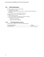
Intel Desktop Board D2550MUD2 Technical Product Specification 1.8 LAN Subsystem The LAN subsystem consists of the following: • Intel NM10 Express Chipset • Intel 82574L Gigabit Ethernet Controller for 10/100/1000 Mb/s Ethernet LAN connectivity • RJ-45 LAN connector with integrated status LEDs ... that supports the Ethernet controller • Conventional PCI bus power management Supports ACPI technology Supports LAN wake capabilities 1.8.1 LAN Subsystem Drivers LAN drivers are available from Intel's World Wide Web site. For information about Obtaining LAN...
Intel Desktop Board D2550MUD2 Technical Product Specification 1.8 LAN Subsystem The LAN subsystem consists of the following: • Intel NM10 Express Chipset • Intel 82574L Gigabit Ethernet Controller for 10/100/1000 Mb/s Ethernet LAN connectivity • RJ-45 LAN connector with integrated status LEDs ... that supports the Ethernet controller • Conventional PCI bus power management Supports ACPI technology Supports LAN wake capabilities 1.8.1 LAN Subsystem Drivers LAN drivers are available from Intel's World Wide Web site. For information about Obtaining LAN...
Technical product specification
Page 27
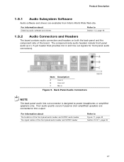
Poor audio quality occurs if passive (non-amplified) speakers are available from Intel's World Wide Web site. For information about Obtaining audio software and drivers Refer to Section 1.2, page 16 1.9.2 Audio Connectors and Headers The board contains audio connectors and headers on both ... audio header and S/PDIF header Refer to power headphones or amplified speakers only. Product Description 1.9.1 Audio Subsystem Software Audio software and drivers are connected to this output. Back Panel Audio Connectors NOTE The back panel audio line out connector is designed to Figure 11,...
Poor audio quality occurs if passive (non-amplified) speakers are available from Intel's World Wide Web site. For information about Obtaining audio software and drivers Refer to Section 1.2, page 16 1.9.2 Audio Connectors and Headers The board contains audio connectors and headers on both ... audio header and S/PDIF header Refer to power headphones or amplified speakers only. Product Description 1.9.1 Audio Subsystem Software Audio software and drivers are connected to this output. Back Panel Audio Connectors NOTE The back panel audio line out connector is designed to Figure 11,...

Technical product specification
Page 30
Intel Desktop Board D2550MUD2 Technical Product Specification 1.11 Power Management Power management is implemented at several levels, including: • Software support through Advanced Configuration and Power Interface (ACPI) • .../G5 - sleeping state) Less than four seconds On (ACPI G0 - working state) More than 15-watt system operation in boards may require an ACPI-aware driver), video displays, and hard disk drives • Methods for achieving less than four seconds Sleep (ACPI G1 - Soft off) Fail safe power-off ) 30 Soft...
Intel Desktop Board D2550MUD2 Technical Product Specification 1.11 Power Management Power management is implemented at several levels, including: • Software support through Advanced Configuration and Power Interface (ACPI) • .../G5 - sleeping state) Less than four seconds On (ACPI G0 - working state) More than 15-watt system operation in boards may require an ACPI-aware driver), video displays, and hard disk drives • Methods for achieving less than four seconds Sleep (ACPI G1 - Soft off) Fail safe power-off ) 30 Soft...
Technical product specification
Page 32
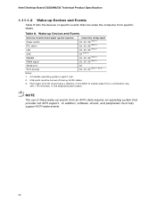
... WAKE# PME# signal ...from an ACPI state requires an operating system that provides full ACPI support. In addition, software, drivers, and peripherals must be turned off during S4/S5 states. 3. Intel Desktop Board D2550MUD2 Technical Product Specification 1.11.1.2 Wake-up Devices and Events Table 8 lists the devices or specific events that can wake...
... WAKE# PME# signal ...from an ACPI state requires an operating system that provides full ACPI support. In addition, software, drivers, and peripherals must be turned off during S4/S5 states. 3. Intel Desktop Board D2550MUD2 Technical Product Specification 1.11.1.2 Wake-up Devices and Events Table 8 lists the devices or specific events that can wake...

Technical product specification
Page 68
...you apply power to enter and configure the BIOS Setup program and the maintenance menu. 4. After the operating system loads the USB drivers, all legacy and non-legacy USB devices are recognized by the operating system, and Legacy USB support from the BIOS is set to... to access the BIOS Setup program, and to install an operating system that Legacy USB support in the BIOS Setup program.) 6. Intel Desktop Board D2550MUD2 Technical Product Specification 3.5 Legacy USB Support Legacy USB support enables USB devices to Enabled and follow the operating system's installation instructions. ...
...you apply power to enter and configure the BIOS Setup program and the maintenance menu. 4. After the operating system loads the USB drivers, all legacy and non-legacy USB devices are recognized by the operating system, and Legacy USB support from the BIOS is set to... to access the BIOS Setup program, and to install an operating system that Legacy USB support in the BIOS Setup program.) 6. Intel Desktop Board D2550MUD2 Technical Product Specification 3.5 Legacy USB Support Legacy USB support enables USB devices to Enabled and follow the operating system's installation instructions. ...
Technical product specification
Page 77
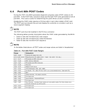
... - 0x1F 0x21 - 0x29 0x2A - 0x2F 0x31 - 0x35 0x36 - 0x3F PEI phase pre MRC execution MRC memory detection PEI phase post MRC execution Recovery Platform DXE driver 0x41 - 0x4F 0x50 - 0x5F 0x60 - 0x6F CPU Initialization (PEI, DXE, SMM) I /O port 80h. For future use 77 The POST card can decode the port and...
... - 0x1F 0x21 - 0x29 0x2A - 0x2F 0x31 - 0x35 0x36 - 0x3F PEI phase pre MRC execution MRC memory detection PEI phase post MRC execution Recovery Platform DXE driver 0x41 - 0x4F 0x50 - 0x5F 0x60 - 0x6F CPU Initialization (PEI, DXE, SMM) I /O port 80h. For future use 77 The POST card can decode the port and...

Technical product specification
Page 78
... Basic chipset initialization LAN init Exit early platform init driver PEI SMBUS SMBUS driver init Entry to SMBUS execute read/write Exit SMBUS execute read/write Memory MRC entry point Detecting presence of memory DIMMs Override Detected DIMM settings Configuring memory. Intel Desktop Board D2550MUD2 Technical Product Specification Table 42. Testing memory PEIMs/Recovery...
... Basic chipset initialization LAN init Exit early platform init driver PEI SMBUS SMBUS driver init Entry to SMBUS execute read/write Exit SMBUS execute read/write Memory MRC entry point Detecting presence of memory DIMMs Override Detected DIMM settings Configuring memory. Intel Desktop Board D2550MUD2 Technical Product Specification Table 42. Testing memory PEIMs/Recovery...

Technical product specification
Page 79
... Resetting USB bus 0x59 Reserved for USB 0x5A 0x5B ATA/ATAPI/SATA Resetting PATA/SATA bus and all devices Reserved for ATA BDS 0x60 BDS driver entry point initialize 0x61 BDS service routine entry point (can be called multiple times) 0x62 BDS Step2 0x63 BDS Step3 0x64 0x65 0x66 BDS Step4...
... Resetting USB bus 0x59 Reserved for USB 0x5A 0x5B ATA/ATAPI/SATA Resetting PATA/SATA bus and all devices Reserved for ATA BDS 0x60 BDS driver entry point initialize 0x61 BDS service routine entry point (can be called multiple times) 0x62 BDS Step2 0x63 BDS Step3 0x64 0x65 0x66 BDS Step4...

Technical product specification
Page 81
... all devices 28 Testing memory 90 Resetting keyboard 94 Clearing keyboard input buffer E7 Waiting for user input 00 Ready to boot A3 Legacy USB driver disconnect 81 Board Status and Error Messages Table 43.
... all devices 28 Testing memory 90 Resetting keyboard 94 Clearing keyboard input buffer E7 Waiting for user input 00 Ready to boot A3 Legacy USB driver disconnect 81 Board Status and Error Messages Table 43.


