Product Guide
Page 5
... 19 Power Connectors 19 Fan Headers 19 +5 V Standby Power Indicator LED 19 LAN Wake Capabilities 20 Wake from USB 21 Wake from PS/2 Keyboard/Mouse 21 PME# Wakeup Support 21 Battery ...21 Real-Time Clock 21 2 Installing and Replacing Desktop Board Components Before You Begin 23... Precautions 24 Prevent Power Supply Overload 24 Observe Safety and Regulatory Requirements 24 Installing the I/O Shield 25 Installing and Removing the Desktop Board 26 Installing and Removing Memory 27 Installing DIMMs 27 Removing DIMMs 29 Connecting the IDE Cable 29 Connecting the Serial ATA (SATA...
... 19 Power Connectors 19 Fan Headers 19 +5 V Standby Power Indicator LED 19 LAN Wake Capabilities 20 Wake from USB 21 Wake from PS/2 Keyboard/Mouse 21 PME# Wakeup Support 21 Battery ...21 Real-Time Clock 21 2 Installing and Replacing Desktop Board Components Before You Begin 23... Precautions 24 Prevent Power Supply Overload 24 Observe Safety and Regulatory Requirements 24 Installing the I/O Shield 25 Installing and Removing the Desktop Board 26 Installing and Removing Memory 27 Installing DIMMs 27 Removing DIMMs 29 Connecting the IDE Cable 29 Connecting the Serial ATA (SATA...
Product Guide
Page 6
Intel Desktop Board D201GLY2 Product Guide Connecting the Front Panel Header 34 Connecting the Chassis Fan 35 Connecting Supply Power Cables 36 Setting the Desktop Board Jumpers 37 Front Panel Audio Header/Jumper Block 37 BIOS Configuration Jumper 38 Clearing Passwords 39 Replacing the Battery 40 3 Updating the BIOS Updating the BIOS with the Intel...Declaration of Conformity Statement 50 Product Ecology Statements 51 Recycling Considerations 51 Lead-free 2LI/Pb-free 2LI Board 54 Restriction of Hazardous Substances (RoHS 55 European Union RoHS 55 China RoHS 55 EMC Regulations 58 ...
Intel Desktop Board D201GLY2 Product Guide Connecting the Front Panel Header 34 Connecting the Chassis Fan 35 Connecting Supply Power Cables 36 Setting the Desktop Board Jumpers 37 Front Panel Audio Header/Jumper Block 37 BIOS Configuration Jumper 38 Clearing Passwords 39 Replacing the Battery 40 3 Updating the BIOS Updating the BIOS with the Intel...Declaration of Conformity Statement 50 Product Ecology Statements 51 Recycling Considerations 51 Lead-free 2LI/Pb-free 2LI Board 54 Restriction of Hazardous Substances (RoHS 55 European Union RoHS 55 China RoHS 55 EMC Regulations 58 ...
Product Guide
Page 7
...Friendly Use Period Mark 56 14. Product Certification Markings 60 vii Desktop Boards D201GLY2 Components 12 3. Intel Desktop Board D201GLY2 Components 11 2. Location of the Standby Power Indicator 20 5. ...Feature Summary 9 2. Hi-Speed USB 2.0 Header Signal Names 34 6. Back Panel Audio Connectors 15 3. Installing a DIMM 28 9. Desktop Board D201GLY2 China RoHS Material Self Declaration Table 57 Tables 1. Use DDR2 DIMMs 27 8. Location of the Chassis Fan...
...Friendly Use Period Mark 56 14. Product Certification Markings 60 vii Desktop Boards D201GLY2 Components 12 3. Intel Desktop Board D201GLY2 Components 11 2. Location of the Standby Power Indicator 20 5. ...Feature Summary 9 2. Hi-Speed USB 2.0 Header Signal Names 34 6. Back Panel Audio Connectors 15 3. Installing a DIMM 28 9. Desktop Board D201GLY2 China RoHS Material Self Declaration Table 57 Tables 1. Use DDR2 DIMMs 27 8. Location of the Chassis Fan...
Product Guide
Page 12
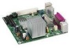
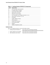
Intel Desktop Board D201GLY2 Product Guide Table 2. Desktop Boards D201GLY2 Components Label A B C D E F G H I J K L M N Description PCI bus add-in card connector Hi-speed USB 2.0 headers Front panel audio header Back panel connectors Rear fan (3-pin) header 12 V processor core voltage connector (2 x 2) Main power ... about: • Desktop Board D201GLY2 • Audio software and utilities • LAN software and drivers http://www.intel.com/design/motherbd http://support.intel.com/support/motherboards/desktop http://www.intel.com/design/motherbd http://www.intel.com/design/motherbd 12...
Intel Desktop Board D201GLY2 Product Guide Table 2. Desktop Boards D201GLY2 Components Label A B C D E F G H I J K L M N Description PCI bus add-in card connector Hi-speed USB 2.0 headers Front panel audio header Back panel connectors Rear fan (3-pin) header 12 V processor core voltage connector (2 x 2) Main power ... about: • Desktop Board D201GLY2 • Audio software and utilities • LAN software and drivers http://www.intel.com/design/motherbd http://support.intel.com/support/motherboards/desktop http://www.intel.com/design/motherbd http://www.intel.com/design/motherbd 12...
Product Guide
Page 18
...password restricts who can boot the computer. If only the supervisor password is set , you install a PCI add-in card. Intel Desktop Board D201GLY2 Product Guide IDE Auto Configuration If you can enter either the supervisor password or the user password to boot the computer. Security...set , pressing at several levels, including: • Advanced Configuration and Power Interface (ACPI) • Hardware support: ― Power connectors ― Fan headers ― +5 V standby power indicator LED ― LAN Wake capabilities ― Wake from USB ― Wake from PS/2 keyboard/mouse ...
...password restricts who can boot the computer. If only the supervisor password is set , you install a PCI add-in card. Intel Desktop Board D201GLY2 Product Guide IDE Auto Configuration If you can enter either the supervisor password or the user password to boot the computer. Security...set , pressing at several levels, including: • Advanced Configuration and Power Interface (ACPI) • Hardware support: ― Power connectors ― Fan headers ― +5 V standby power indicator LED ― LAN Wake capabilities ― Wake from USB ― Wake from PS/2 keyboard/mouse ...
Product Guide
Page 19
...installing or removing any attached devices. See Figure 13 on page 35 for the location of a computer. Fan Headers The Desktop Board has a 3-pin processor fan header and a 3-pin chassis fan header. Failure to the system. This includes the DIMM socket and the PCI bus connector, even though ...Figure 12 on page 36 for the location of ACPI with the Desktop Board requires an operating system that provides full ACPI support. Hardware Support Power Connectors The Desktop Board has two power connectors. The use of the chassis fan header. +5 V Standby Power Indicator LED CAUTION If the AC ...
...installing or removing any attached devices. See Figure 13 on page 35 for the location of a computer. Fan Headers The Desktop Board has a 3-pin processor fan header and a 3-pin chassis fan header. Failure to the system. This includes the DIMM socket and the PCI bus connector, even though ...Figure 12 on page 36 for the location of ACPI with the Desktop Board requires an operating system that provides full ACPI support. Hardware Support Power Connectors The Desktop Board has two power connectors. The use of the chassis fan header. +5 V Standby Power Indicator LED CAUTION If the AC ...
Product Guide
Page 23
...8226; Install the I/O shield • Install and remove the Desktop Board • Install and remove memory • Connect the IDE cable • Connect the SATA cable • Connect internal headers • Connect chassis fan and power supply cables • Set the BIOS configuration and...performing any telecommunications links, networks, or modems before you begin installing the Desktop Board: • Always follow the steps in each procedure in this chapter. 2 Installing and Replacing Desktop Board Components This chapter tells you can provide some ESD protection by wearing an ...
...8226; Install the I/O shield • Install and remove the Desktop Board • Install and remove memory • Connect the IDE cable • Connect the SATA cable • Connect internal headers • Connect chassis fan and power supply cables • Set the BIOS configuration and...performing any telecommunications links, networks, or modems before you begin installing the Desktop Board: • Always follow the steps in each procedure in this chapter. 2 Installing and Replacing Desktop Board Components This chapter tells you can provide some ESD protection by wearing an ...
Product Guide
Page 35
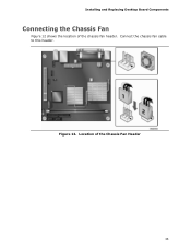
Installing and Replacing Desktop Board Components Connecting the Chassis Fan Figure 12 shows the location of the Chassis Fan Header 35 Figure 12. Connect the chassis fan cable to this header. Location of the chassis fan header.
Installing and Replacing Desktop Board Components Connecting the Chassis Fan Figure 12 shows the location of the Chassis Fan Header 35 Figure 12. Connect the chassis fan cable to this header. Location of the chassis fan header.


