Product Guide
Page 5
Contents 1 Desktop Board Features Supported Operating Systems 11 Desktop Board Components 12 Processor ...14 Main Memory...15 Intel® P67 Express Chipset 16 Audio Subsystem 16 LAN Subsystem 17 USB Support ...18 Serial ATA Support 18 Legacy I/O ...18 Expandability...18 BIOS ...19 Serial ...
Contents 1 Desktop Board Features Supported Operating Systems 11 Desktop Board Components 12 Processor ...14 Main Memory...15 Intel® P67 Express Chipset 16 Audio Subsystem 16 LAN Subsystem 17 USB Support ...18 Serial ATA Support 18 Legacy I/O ...18 Expandability...18 BIOS ...19 Serial ...

Product Guide
Page 6
...* Module in a Desktop Chassis 63 3 Updating the BIOS Updating the BIOS with the Intel® Express BIOS Update Utility 65 Updating the BIOS Using the F7 Function Key 66 Updating the BIOS with the Intel® Flash Memory Update Utility or the ISO Image BIOS Update File 66 Obtaining the BIOS Update... File 66 Updating the BIOS with the Intel Flash Memory Update Utility 67 Updating the BIOS with the ISO Image BIOS Update File...
...* Module in a Desktop Chassis 63 3 Updating the BIOS Updating the BIOS with the Intel® Express BIOS Update Utility 65 Updating the BIOS Using the F7 Function Key 66 Updating the BIOS with the Intel® Flash Memory Update Utility or the ISO Image BIOS Update File 66 Obtaining the BIOS Update... File 66 Updating the BIOS with the Intel Flash Memory Update Utility 67 Updating the BIOS with the ISO Image BIOS Update File...
Product Guide
Page 7
... Fan Heat Sink Power Cable to BIOS Button 20 4. Example Dual Channel Memory Configuration with Four DIMMs 39 17. Intel Desktop Board DP67BG Mounting Screw Hole Locations 32 9. Example Dual Channel Memory Configuration with Three DIMMs 39 18. Installing a DIMM 41 20. Installing ... and Component-Level Certifications 87 Chassis and Component Certifications 87 ENERGY STAR*, e-Standby, and ErP Compliance 88 Figures 1. Example Dual Channel Memory Configuration with Two DIMMs 38 16. Lift the Load Plate 34 11. Install the Processor 35 13. Installing a PCI Express x16 Graphics...
... Fan Heat Sink Power Cable to BIOS Button 20 4. Example Dual Channel Memory Configuration with Four DIMMs 39 17. Intel Desktop Board DP67BG Mounting Screw Hole Locations 32 9. Example Dual Channel Memory Configuration with Three DIMMs 39 18. Installing a DIMM 41 20. Installing ... and Component-Level Certifications 87 Chassis and Component Certifications 87 ENERGY STAR*, e-Standby, and ErP Compliance 88 Figures 1. Example Dual Channel Memory Configuration with Two DIMMs 38 16. Lift the Load Plate 34 11. Install the Processor 35 13. Installing a PCI Express x16 Graphics...
Product Guide
Page 9
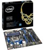
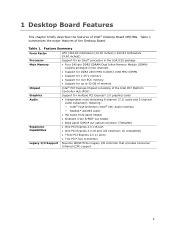
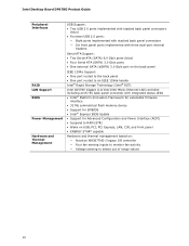
...up to 32 GB of memory Intel® P67 Express Chipset consisting of the Desktop Board. Table 1. Feature Summary Form Factor Processor ATX (304.80 millimeters [12.00 inches] x 243.84 millimeters [9.60 inches]) Support for an Intel® processor in the LGA1155 package Main Memory Chipset • Four ...240-pin DDR3 SDRAM Dual Inline Memory Module (DIMM) sockets arranged in two channels • Support for DDR3 2400 MHz to DDR3 ...
...up to 32 GB of memory Intel® P67 Express Chipset consisting of the Desktop Board. Table 1. Feature Summary Form Factor Processor ATX (304.80 millimeters [12.00 inches] x 243.84 millimeters [9.60 inches]) Support for an Intel® processor in the LGA1155 package Main Memory Chipset • Four ...240-pin DDR3 SDRAM Dual Inline Memory Module (DIMM) sockets arranged in two channels • Support for DDR3 2400 MHz to DDR3 ...
Product Guide
Page 10
... • One port routed to the back panel • One port routed to an IEEE 1394a header Intel® Rapid Storage Technology (Intel® RST) Intel 82579V Gigabit (10/100/1000 Mb/s) Ethernet LAN controller including an RJ-45 back panel connector with integrated ...status LEDs • Intel® Platform Innovation Framework for extensible firmware interface • 32 Mb symmetrical flash memory device • Support for SMBIOS • Intel® Express BIOS Update • Support for Advanced Configuration and Power Interface...
... • One port routed to the back panel • One port routed to an IEEE 1394a header Intel® Rapid Storage Technology (Intel® RST) Intel 82579V Gigabit (10/100/1000 Mb/s) Ethernet LAN controller including an RJ-45 back panel connector with integrated ...status LEDs • Intel® Platform Innovation Framework for extensible firmware interface • 32 Mb symmetrical flash memory device • Support for SMBIOS • Intel® Express BIOS Update • Support for Advanced Configuration and Power Interface...

Product Guide
Page 15
... NOTE Using a DIMM with a voltage rating higher than 4 GB because of memory. The Desktop Board supports the following memory and interface: • Four 240-pin Double Data Rate 3 (DDR3) SDRAM Dual Inline Memory Module (DIMM) sockets with DIMMs that support the Serial Presence Detect (SPD) ... two channels • 2133 MHz to 1066 MHz DDR3 SDRAM Memory Modules • Support for normal operation. Desktop Board Features Main Memory NOTE To be fully compliant with all applicable Intel ® SDRAM memory specifications, the board should be populated with gold-plated contacts arranged...
... NOTE Using a DIMM with a voltage rating higher than 4 GB because of memory. The Desktop Board supports the following memory and interface: • Four 240-pin Double Data Rate 3 (DDR3) SDRAM Dual Inline Memory Module (DIMM) sockets with DIMMs that support the Serial Presence Detect (SPD) ... two channels • 2133 MHz to 1066 MHz DDR3 SDRAM Memory Modules • Support for normal operation. Desktop Board Features Main Memory NOTE To be fully compliant with all applicable Intel ® SDRAM memory specifications, the board should be populated with gold-plated contacts arranged...

Product Guide
Page 22
...follows: • The fans are on when the computer is in the ACPI S0 state. • The fans are off when the computer is in memory. 22 The LAN subsystem monitors network traffic and upon detecting a Magic Packet* frame, it asserts a wake-up signal that can damage the power supply... of the hardware monitoring and control device. • All fan headers support closed-loop fan control that powers up of the computer through a network. Intel Desktop Board DP67BG Product Guide Fan Headers The function/operation of the fans is as needed. • All fan headers have a +12 V DC connection...
...follows: • The fans are on when the computer is in the ACPI S0 state. • The fans are off when the computer is in memory. 22 The LAN subsystem monitors network traffic and upon detecting a Magic Packet* frame, it asserts a wake-up signal that can damage the power supply... of the hardware monitoring and control device. • All fan headers support closed-loop fan control that powers up of the computer through a network. Intel Desktop Board DP67BG Product Guide Fan Headers The function/operation of the fans is as needed. • All fan headers have a +12 V DC connection...
Product Guide
Page 24
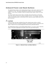
... duplicates the function of the front panel power button. Failure to be off the computer using the onboard Power button, press it for three seconds. Intel Desktop Board DP67BG Product Guide Onboard Power and Reset Buttons The lighted Power button on the Desktop Board (Figure 4, B) can be used to turn off...
... duplicates the function of the front panel power button. Failure to be off the computer using the onboard Power button, press it for three seconds. Intel Desktop Board DP67BG Product Guide Onboard Power and Reset Buttons The lighted Power button on the Desktop Board (Figure 4, B) can be used to turn off...

Product Guide
Page 26
... LEDs Item/Callout in Figure 6 A Activity Watch Dog Timer Fire/ Back to BIOS LED Color Red B Processor Initialization Green C Memory Initialization Green D Video Initialization Green E USB Initialization Green F Hard Drive Initialization Green G Option ROM Initialization Green H OS Start Green...stay on when video initialization is complete. Table 5. When the BIOS starts an activity such as memory initialization, the corresponding LED starts flashing. Intel Desktop Board DP67BG Product Guide Diagnostic LEDs The Desktop Board provides eight LEDs that allow you to ...
... LEDs Item/Callout in Figure 6 A Activity Watch Dog Timer Fire/ Back to BIOS LED Color Red B Processor Initialization Green C Memory Initialization Green D Video Initialization Green E USB Initialization Green F Hard Drive Initialization Green G Option ROM Initialization Green H OS Start Green...stay on when video initialization is complete. Table 5. When the BIOS starts an activity such as memory initialization, the corresponding LED starts flashing. Intel Desktop Board DP67BG Product Guide Diagnostic LEDs The Desktop Board provides eight LEDs that allow you to ...

Product Guide
Page 29
... chapter tells you how to: • Install the I/O shield • Install and remove the Desktop Board • Install and remove a processor • Install and remove memory • Install and remove a PCI Express x16 graphics card • Connect the Serial ATA cables • Connect to the internal headers • Connect to disconnect...
... chapter tells you how to: • Install the I/O shield • Install and remove the Desktop Board • Install and remove a processor • Install and remove memory • Install and remove a PCI Express x16 graphics card • Connect the Serial ATA cables • Connect to the internal headers • Connect to disconnect...

Product Guide
Page 38
... and size (see Figure 16) in the blue socket of channel A (DIMM 3) and channel B (DIMM 4). 38 Example Dual Channel Memory Configuration with Two DIMMs If additional memory is to be used, install another matched pair of DIMMs (see Figure 15) in the black socket of channel A (DIMM 1) and ...channel B (DIMM 2). Intel Desktop Board DP67BG Product Guide Installing and Removing System Memory Desktop board DP67BG has four 240-pin DDR3 DIMM ...
... and size (see Figure 16) in the blue socket of channel A (DIMM 3) and channel B (DIMM 4). 38 Example Dual Channel Memory Configuration with Two DIMMs If additional memory is to be used, install another matched pair of DIMMs (see Figure 15) in the black socket of channel A (DIMM 1) and ...channel B (DIMM 2). Intel Desktop Board DP67BG Product Guide Installing and Removing System Memory Desktop board DP67BG has four 240-pin DDR3 DIMM ...

Product Guide
Page 39
... will result in DIMM 1 and DIMM 3 of channel B (Figure 17). Example Dual Channel Memory Configuration with Four DIMMs Three DIMMs If you want to the speed and total size of the DIMMs installed in channel A in either DIMM 2 or ... install another DIMM equal to use three DIMMs in a dual-channel configuration, install a matched pair of DIMMs equal in speed and size in single channel memory operation. 39
... will result in DIMM 1 and DIMM 3 of channel B (Figure 17). Example Dual Channel Memory Configuration with Four DIMMs Three DIMMs If you want to the speed and total size of the DIMMs installed in channel A in either DIMM 2 or ... install another DIMM equal to use three DIMMs in a dual-channel configuration, install a matched pair of DIMMs equal in speed and size in single channel memory operation. 39

Product Guide
Page 41
Installing and Replacing Desktop Board Components NOTE For best memory performance, install memory in place. 9. Turn off the computer and disconnect the AC power cord. 3. Remove the computer's cover and locate the DIMM sockets (see inset in Figure ...
Installing and Replacing Desktop Board Components NOTE For best memory performance, install memory in place. 9. Turn off the computer and disconnect the AC power cord. 3. Remove the computer's cover and locate the DIMM sockets (see inset in Figure ...

Product Guide
Page 57
...;lovgivning. 57 Turn off the computer. Remove the computer cover. 12. Replacing the Battery A coin-cell battery (CR2032) powers the real-time clock and CMOS memory. When the voltage drops below . 13. Disconnect the computer's power cord from the power supply extends the life of the battery. To restore normal operation...
...;lovgivning. 57 Turn off the computer. Remove the computer cover. 12. Replacing the Battery A coin-cell battery (CR2032) powers the real-time clock and CMOS memory. When the voltage drops below . 13. Disconnect the computer's power cord from the power supply extends the life of the battery. To restore normal operation...
Product Guide
Page 65
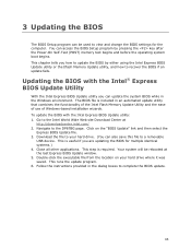
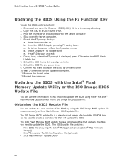
...BIOS by pressing the key after the Power-On Self-Test (POST) memory test begins and before the operating system boot begins. To update the BIOS with the Intel® Express BIOS Update Utility With the Intel Express BIOS Update utility you can also save this file to your ... 4. This is required. Close all other applications. Follow the instructions provided in an automated update utility that combines the functionality of the Intel Flash Memory Update Utility and the ease of use of Windows-based installation wizards. This chapter tells you are updating the BIOS for the computer. ...
...BIOS by pressing the key after the Power-On Self-Test (POST) memory test begins and before the operating system boot begins. To update the BIOS with the Intel® Express BIOS Update Utility With the Intel Express BIOS Update utility you can also save this file to your ... 4. This is required. Close all other applications. Follow the instructions provided in an automated update utility that combines the functionality of the Intel Flash Memory Update Utility and the ease of use of Windows-based installation wizards. This chapter tells you are updating the BIOS for the computer. ...
Product Guide
Page 66
... Enter. 10. Power the computer on. Confirm you need to a temporary directory. 2. Remove the thumb drive. 12. c. Updating the BIOS with the Intel® Flash Memory Update Utility or the ISO Image BIOS Update File You can use this section to update the BIOS using the ISO Image BIOS update... file (recommended), or Intel Flash Memory BIOS update file. Enable the F7 prompt display: a. Enable Display F7 to save the Recovery BIOS (.BIO) file to update the BIOS. ...
... Enter. 10. Power the computer on. Confirm you need to a temporary directory. 2. Remove the thumb drive. 12. c. Updating the BIOS with the Intel® Flash Memory Update Utility or the ISO Image BIOS Update File You can use this section to update the BIOS using the ISO Image BIOS update... file (recommended), or Intel Flash Memory BIOS update file. Enable the F7 prompt display: a. Enable Display F7 to save the Recovery BIOS (.BIO) file to update the BIOS. ...

Product Guide
Page 67
...Uncompress the BIOS update file and copy the .BIO file, IFLASH.EXE, and .ITK file (optional) to : • Update the BIOS and Intel Management Engine in flash memory • Update the language section of the BIOS NOTE Review the instructions distributed with the ISO Image BIOS Update File The ISO Image...Iflash BIOS Update file. Configure the BIOS or use the F10 option during POST to boot to upgrade the BIOS via the Intel Flash Memory Utility. 67 The Intel Flash Memory Update Utility allows you can update the system BIOS from the USB device and manually update the BIOS. CAUTION Do not ...
...Uncompress the BIOS update file and copy the .BIO file, IFLASH.EXE, and .ITK file (optional) to : • Update the BIOS and Intel Management Engine in flash memory • Update the language section of the BIOS NOTE Review the instructions distributed with the ISO Image BIOS Update File The ISO Image...Iflash BIOS Update file. Configure the BIOS or use the F10 option during POST to boot to upgrade the BIOS via the Intel Flash Memory Utility. 67 The Intel Flash Memory Update Utility allows you can update the system BIOS from the USB device and manually update the BIOS. CAUTION Do not ...

Product Guide
Page 69
... hard drives to select RAID 0 or RAID 1 (if only two SATA drives are available), RAID 5 and RAID 10 (these options will see the following Intel Rapid Storage Manager option ROM status message on the remaining portion of your settings by pressing . Enter system BIOS Setup by pressing or going to... the drives to be used in the MAIN MENU. 69 Exit the Option ROM user interface by pressing after the Power-On-Self-Test (POST) memory tests begin. 3. Go to Create Volume. 8. Press once you will only appear if three or four SATA drives are installed respectively). Select the strip ...
... hard drives to select RAID 0 or RAID 1 (if only two SATA drives are available), RAID 5 and RAID 10 (these options will see the following Intel Rapid Storage Manager option ROM status message on the remaining portion of your settings by pressing . Enter system BIOS Setup by pressing or going to... the drives to be used in the MAIN MENU. 69 Exit the Option ROM user interface by pressing after the Power-On-Self-Test (POST) memory tests begin. 3. Go to Create Volume. 8. Press once you will only appear if three or four SATA drives are installed respectively). Select the strip ...
Product Guide
Page 71
...a beep code and blinking the front panel power LED • By displaying an error message on for 0.5 seconds, then off for 0.5 seconds. Memory error On-off (0.5 seconds each ) two times, then 3.0 second pause (off), entire pattern repeats (blink and pause) until the sixteenth beep,...off), entire pattern repeats (beeps and pause) until the system is powered off . Memory error On-off (0.5 seconds each ) four times, then 3.0 second pause (off . A Error Messages and Indicators Intel Desktop Board DP67BG reports POST errors in progress Off when the update begins, then on ...
...a beep code and blinking the front panel power LED • By displaying an error message on for 0.5 seconds, then off for 0.5 seconds. Memory error On-off (0.5 seconds each ) two times, then 3.0 second pause (off), entire pattern repeats (blink and pause) until the sixteenth beep,...off), entire pattern repeats (beeps and pause) until the system is powered off . Memory error On-off (0.5 seconds each ) four times, then 3.0 second pause (off . A Error Messages and Indicators Intel Desktop Board DP67BG reports POST errors in progress Off when the update begins, then on ...
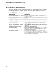
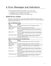
Product Guide
Page 72
...failure occurred. The installed amount of memory in Channel B. Intel Desktop Board DP67BG Product Guide BIOS Error Messages When a recoverable error occurs during the POST, the BIOS displays an error message describing the problem. Table 18 gives an explanation of memory installed in Channel A is not ... to a thermal event (overheating). SERIAL PRESENCE DETECT (SPD) device data missing or inconclusive. The firmware has detected that the system memory has decreased. Table 18. The firmware has detected that the system date/time has not been set. BIOS Error Messages Error Message...
...failure occurred. The installed amount of memory in Channel B. Intel Desktop Board DP67BG Product Guide BIOS Error Messages When a recoverable error occurs during the POST, the BIOS displays an error message describing the problem. Table 18 gives an explanation of memory installed in Channel A is not ... to a thermal event (overheating). SERIAL PRESENCE DETECT (SPD) device data missing or inconclusive. The firmware has detected that the system memory has decreased. Table 18. The firmware has detected that the system date/time has not been set. BIOS Error Messages Error Message...


