
Product Specification
Page 5
Contents 1 Product Description 1.1 Overview 10 1.1.1 Feature Summary 10 1.1.2 Board Layout 12 1.1.3 Block Diagram 14 1.2 Online Support 15 1.3 Processor 15 1.4 System Memory 16 1.4.1 Memory Configurations 17 1.5 Intel® 945GC Chipset 17 1.5.1 Intel 945GC Graphics Subsystem 17 1.5.2 USB 19 1.5.3 IDE Support 19 1.5.4 Real-Time Clock, CMOS SRAM, and Battery 21 1.6 Legacy I/O Controller 21 1.6.1 Diskette Drive Controller...
Contents 1 Product Description 1.1 Overview 10 1.1.1 Feature Summary 10 1.1.2 Board Layout 12 1.1.3 Block Diagram 14 1.2 Online Support 15 1.3 Processor 15 1.4 System Memory 16 1.4.1 Memory Configurations 17 1.5 Intel® 945GC Chipset 17 1.5.1 Intel 945GC Graphics Subsystem 17 1.5.2 USB 19 1.5.3 IDE Support 19 1.5.4 Real-Time Clock, CMOS SRAM, and Battery 21 1.6 Legacy I/O Controller 21 1.6.1 Diskette Drive Controller...

Product Specification
Page 7
... Power/Sleep LED Header 42 18. Front Panel Header 43 19. Serial ATA Connectors 40 12. Main Power Connector 41 16. Processor Core Power Connector 42 17. BIOS Setup Configuration Jumper Settings 47 22. Back Panel Audio Connector Options 23 4. Location of the ... Fan Header Current Capability 50 24. Block Diagram 14 3. Connection Diagram for a Two-Color Power LED 44 21. Feature Summary 10 2. Processor Fan Header 41 14. Thermal Considerations for Components 52 25. Boot Device Menu Options 60 vii Contents Figures 1. Board Components 12 2. Thermal Sensors...
... Power/Sleep LED Header 42 18. Front Panel Header 43 19. Serial ATA Connectors 40 12. Main Power Connector 41 16. Processor Core Power Connector 42 17. BIOS Setup Configuration Jumper Settings 47 22. Back Panel Audio Connector Options 23 4. Location of the ... Fan Header Current Capability 50 24. Block Diagram 14 3. Connection Diagram for a Two-Color Power LED 44 21. Feature Summary 10 2. Processor Fan Header 41 14. Thermal Considerations for Components 52 25. Boot Device Menu Options 60 vii Contents Figures 1. Board Components 12 2. Thermal Sensors...

Product Specification
Page 9
1 Product Description What This Chapter Contains 1.1 Overview 10 1.2 Online Support 15 1.3 Processor 15 1.4 System Memory 16 1.5 Intel® 945GC Chipset 17 1.6 Legacy I/O Controller 21 1.7 Audio Subsystem 22 1.8 LAN Subsystem 23 1.9 Hardware Management Subsystem 25 1.10 Power Management 27 9
1 Product Description What This Chapter Contains 1.1 Overview 10 1.2 Online Support 15 1.3 Processor 15 1.4 System Memory 16 1.5 Intel® 945GC Chipset 17 1.6 Legacy I/O Controller 21 1.7 Audio Subsystem 22 1.8 LAN Subsystem 23 1.9 Hardware Management Subsystem 25 1.10 Power Management 27 9
Product Specification
Page 10
... an LGA775 socket with an 800 or 533 MHz system bus • Intel® Pentium® 4 processor in an LGA775 socket with an 800 or 533 MHz system bus • Intel® Celeron® processor 400 series in an LGA775 socket with a 533 MHz system bus • Two 240-pin DDR2 SDRAM ...8226; PS/2 keyboard and mouse ports 10/100 Mbits/sec LAN subsystem using the Realtek RTL8101E-GR Ethernet Controller • Intel® BIOS (resident in an LGA775 socket with an 800 MHz system bus • Intel® Celeron D processor in the SPI Flash device) • Support for up to 2 GB of system memory...
... an LGA775 socket with an 800 or 533 MHz system bus • Intel® Pentium® 4 processor in an LGA775 socket with an 800 or 533 MHz system bus • Intel® Celeron® processor 400 series in an LGA775 socket with a 533 MHz system bus • Two 240-pin DDR2 SDRAM ...8226; PS/2 keyboard and mouse ports 10/100 Mbits/sec LAN subsystem using the Realtek RTL8101E-GR Ethernet Controller • Intel® BIOS (resident in an LGA775 socket with an 800 MHz system bus • Intel® Celeron D processor in the SPI Flash device) • Support for up to 2 GB of system memory...

Product Specification
Page 13
... header B PCI Conventional bus add-in card connector #2 C PCI Conventional bus add-in card connector #1 D Rear chassis fan header E Back panel connectors F Processor core power connector (2 X 2) G Intel 82945GC GMCH H LGA775 processor socket I Processor fan header J DIMM socket K DIMM socket L Main Power connector (2 X 12) M Diskette drive connector N Parallel ATE IDE connector O Battery P Serial ATA connectors...
... header B PCI Conventional bus add-in card connector #2 C PCI Conventional bus add-in card connector #1 D Rear chassis fan header E Back panel connectors F Processor core power connector (2 X 2) G Intel 82945GC GMCH H LGA775 processor socket I Processor fan header J DIMM socket K DIMM socket L Main Power connector (2 X 12) M Diskette drive connector N Parallel ATE IDE connector O Battery P Serial ATA connectors...

Product Specification
Page 15
... Support To find information about ... Supported processors Refer to: http://www.intel.com/go /findcpu http://www.intel.com/products/desktop/chipsets/index.htm http://downloadcenter.intel.com http://support.intel.com/support/motherboards/desktop/sb/CS025414.htm 1.3 Processor The board is designed to support the following processors: • Intel Core 2 Duo processor in an LGA775 socket with a 1066...
... Support To find information about ... Supported processors Refer to: http://www.intel.com/go /findcpu http://www.intel.com/products/desktop/chipsets/index.htm http://downloadcenter.intel.com http://support.intel.com/support/motherboards/desktop/sb/CS025414.htm 1.3 Processor The board is designed to support the following processors: • Intel Core 2 Duo processor in an LGA775 socket with a 1066...

Product Specification
Page 20
...-66 and ATA-100 are assigned (IRQ 14 and 15). In legacy mode, standard IDE I /O (PIO): processor controls data transfer. • 8237-style DMA: DMA offloads the processor, supporting transfer rates of up to 16 MB/sec. • Ultra DMA: DMA protocol on IDE bus supporting host...The Parallel ATA IDE interface also supports ATAPI devices (such as CD-ROM drives) and ATA devices using the Windows* XP operating system. Intel Desktop Board D945GCPE Technical Product Specification 1.5.3.1 Parallel ATE IDE Interface The ICH7's Parallel ATA IDE controller has one bus-mastering Parallel ATA IDE ...
...-66 and ATA-100 are assigned (IRQ 14 and 15). In legacy mode, standard IDE I /O (PIO): processor controls data transfer. • 8237-style DMA: DMA offloads the processor, supporting transfer rates of up to 16 MB/sec. • Ultra DMA: DMA protocol on IDE bus supporting host...The Parallel ATA IDE interface also supports ATAPI devices (such as CD-ROM drives) and ATA devices using the Windows* XP operating system. Intel Desktop Board D945GCPE Technical Product Specification 1.5.3.1 Parallel ATE IDE Interface The ICH7's Parallel ATA IDE controller has one bus-mastering Parallel ATA IDE ...

Product Specification
Page 25
... a mechanical switch on or off as needed • SMBus interface For information about The functions of the fan headers and sensors for direct monitoring of processor temperature and ambient temperature sensing • Power supply monitoring of five voltages (+5 V, +12 V, +3.3 VSB, +1.5 V, and +VCCP) to detect levels above or below acceptable values •...
... a mechanical switch on or off as needed • SMBus interface For information about The functions of the fan headers and sensors for direct monitoring of processor temperature and ambient temperature sensing • Power supply monitoring of five voltages (+5 V, +12 V, +3.3 VSB, +1.5 V, and +VCCP) to detect levels above or below acceptable values •...

Product Specification
Page 26
Item A B C Description Rear chassis fan Thermal diode, located on processor die Processor fan Figure 5. Thermal Sensors and Fan Headers 26 Intel Desktop Board D945GCPE Technical Product Specification 1.9.4 Thermal Monitoring Figure 5 shows the location of the sensors and fan headers.
Item A B C Description Rear chassis fan Thermal diode, located on processor die Processor fan Figure 5. Thermal Sensors and Fan Headers 26 Intel Desktop Board D945GCPE Technical Product Specification 1.9.4 Thermal Monitoring Figure 5 shows the location of the sensors and fan headers.
Product Specification
Page 28
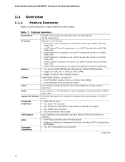
... - For information about ENERGY STAR requirements and recommended configurations Refer to put the system as a whole into a low-power state. Intel Desktop Board D945GCPE Technical Product Specification 1.10.1.1 System States and Power States Under ACPI, the operating system directs all system and device ..., the US Department of wake-up logic. Devices that are being used by battery or external source. sleeping state G1 - Processor stopped C1 - Suspend to disk. Context saved to the system. S5 - Cold boot is disconnected from applications and user settings to http...
... - For information about ENERGY STAR requirements and recommended configurations Refer to put the system as a whole into a low-power state. Intel Desktop Board D945GCPE Technical Product Specification 1.10.1.1 System States and Power States Under ACPI, the operating system directs all system and device ..., the US Department of wake-up logic. Devices that are being used by battery or external source. sleeping state G1 - Processor stopped C1 - Suspend to disk. Context saved to the system. S5 - Cold boot is disconnected from applications and user settings to http...
Product Specification
Page 30
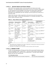
... the S3, S4, or S5 state. • Each fan header is wired to the power state it was in the BIOS Setup program's Boot menu. Intel Desktop Board D945GCPE Technical Product Specification NOTE The use of Wake from USB from an AC power failure, the computer returns to a fan tachometer input... of the Legacy I/O controller for thermal monitoring The signal names of the processor fan header The signal names of the chassis fan header Refer to Figure 9, page 38 Figure 5, page 26 Table 13, page 40 Table 14, page...
... the S3, S4, or S5 state. • Each fan header is wired to the power state it was in the BIOS Setup program's Boot menu. Intel Desktop Board D945GCPE Technical Product Specification NOTE The use of Wake from USB from an AC power failure, the computer returns to a fan tachometer input... of the Legacy I/O controller for thermal monitoring The signal names of the processor fan header The signal names of the chassis fan header Refer to Figure 9, page 38 Figure 5, page 26 Table 13, page 40 Table 14, page...

Product Specification
Page 39
Technical Reference Table 8 lists the component-side connectors and headers identified in card connector 1 D Rear chassis fan header E Processor core power connector (2 X 2) F Processor fan header G Main power connector (2 X 12) H Diskette drive connector I Parallel ATA IDE connector J Serial ATA connector 1 K Serial ATA connector 0 L Auxiliary front panel power LED header M ...
Technical Reference Table 8 lists the component-side connectors and headers identified in card connector 1 D Rear chassis fan header E Processor core power connector (2 X 2) F Processor fan header G Main power connector (2 X 12) H Diskette drive connector I Parallel ATA IDE connector J Serial ATA connector 1 K Serial ATA connector 0 L Auxiliary front panel power LED header M ...

Product Specification
Page 41
...V 13 +3.3 V 2 +3.3 V 14 -12 V 3 Ground 15 Ground 4 +5 V 16 PS-ON# (power supply remote on Intel Desktop boards. a 2 x 2 connector. Failure to the processor voltage regulator and must always be unconnected. 41 Table 15. This connector is compatible with either 2 x 10 or 2 x 12 main power... 2 x 10 main power cable, attach that cable on the rightmost pins of ATX12V power supplies with 2 x 10 connectors previously used . Processor Fan Header Pin Signal Name 1 Ground 2 +12 V 3 FAN_TACH 4 FAN_CONTROL Table 14. The board supports the use of the main power...
...V 13 +3.3 V 2 +3.3 V 14 -12 V 3 Ground 15 Ground 4 +5 V 16 PS-ON# (power supply remote on Intel Desktop boards. a 2 x 2 connector. Failure to the processor voltage regulator and must always be unconnected. 41 Table 15. This connector is compatible with either 2 x 10 or 2 x 12 main power... 2 x 10 main power cable, attach that cable on the rightmost pins of ATX12V power supplies with 2 x 10 connectors previously used . Processor Fan Header Pin Signal Name 1 Ground 2 +12 V 3 FAN_TACH 4 FAN_CONTROL Table 14. The board supports the use of the main power...

Product Specification
Page 42
... The specific SMBus signals are routed to all PCI Conventional bus connectors. PCI Conventional bus add-in card connectors. Table 17. Intel Desktop Board D945GCPE Technical Product Specification Table 16. Note the following add-in card connectors: • PCI Conventional (rev 2.3 ...compliant) bus: two PCI Conventional bus add-in cards with SMBus support to all PCI Conventional bus connectors. Processor Core Power Connector Pin Signal Name Pin 1 Ground 2 3 +12 V 4 Signal Name Ground +12 V 2.2.2.2 Add-in Card Connectors The ...
... The specific SMBus signals are routed to all PCI Conventional bus connectors. PCI Conventional bus add-in card connectors. Table 17. Intel Desktop Board D945GCPE Technical Product Specification Table 16. Note the following add-in card connectors: • PCI Conventional (rev 2.3 ...compliant) bus: two PCI Conventional bus add-in cards with SMBus support to all PCI Conventional bus connectors. Processor Core Power Connector Pin Signal Name Pin 1 Ground 2 3 +12 V 4 Signal Name Ground +12 V 2.2.2.2 Add-in Card Connectors The ...
Product Specification
Page 46
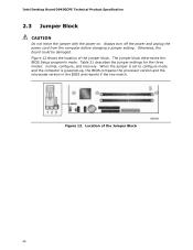
... the three modes: normal, configure, and recovery. When the jumper is set to configure mode and the computer is powered-up, the BIOS compares the processor version and the microcode version in the BIOS and reports if the two match. Figure 12 shows the location of the Jumper Block 46... Intel Desktop Board D945GCPE Technical Product Specification 2.3 Jumper Block CAUTION Do not move the jumper with the power on. Always turn off the power and unplug ...
... the three modes: normal, configure, and recovery. When the jumper is set to configure mode and the computer is powered-up, the BIOS compares the processor version and the microcode version in the BIOS and reports if the two match. Figure 12 shows the location of the Jumper Block 46... Intel Desktop Board D945GCPE Technical Product Specification 2.3 Jumper Block CAUTION Do not move the jumper with the power on. Always turn off the power and unplug ...

Product Specification
Page 49
... Additional power required will depend on the wake devices supported and manufacturing options. Failure to http://support.intel.com/support/motherboards/desktop/sb/CS-026472.htm 49 The power supply must be capable of supported processors), 1 GB DDR2 RAM, one hard disk drive, one optical drive, and all board peripherals enabled,...• The current capability of the +5 VSB line • All timing parameters • All voltage tolerances For example, for a system consisting of a supported 65 W processor (see section 1.3 on page 15 for a list of providing adequate +5 V standby current.
... Additional power required will depend on the wake devices supported and manufacturing options. Failure to http://support.intel.com/support/motherboards/desktop/sb/CS-026472.htm 49 The power supply must be capable of supported processors), 1 GB DDR2 RAM, one hard disk drive, one optical drive, and all board peripherals enabled,...• The current capability of the +5 VSB line • All timing parameters • All voltage tolerances For example, for a system consisting of a supported 65 W processor (see section 1.3 on page 15 for a list of providing adequate +5 V standby current.

Product Specification
Page 50
... instances, damage to the board. Table 23 lists the current capability of the fan headers. Intel makes no warranties or representations that have been tested with Intel desktop boards please refer to maintain required airflow across the processor voltage regulator area. Intel Desktop Board D945GCPE Technical Product Specification 2.5.2 Fan Header Current Capability CAUTION The...
... instances, damage to the board. Table 23 lists the current capability of the fan headers. Intel makes no warranties or representations that have been tested with Intel desktop boards please refer to maintain required airflow across the processor voltage regulator area. Intel Desktop Board D945GCPE Technical Product Specification 2.5.2 Fan Header Current Capability CAUTION The...

Product Specification
Page 51
... exceed the board's maximum operating temperature. Figure 14 shows the locations of up to the voltage regulator circuit. Item A B C D Description Processor voltage regulator area Processor Intel 82945GC GMCH Intel 82801GB ICH7 Figure 14. The processor voltage regulator area (item A in Figure 14) can reach a temperature of the localized high temperature zones. Technical Reference CAUTION Ensure...
... exceed the board's maximum operating temperature. Figure 14 shows the locations of up to the voltage regulator circuit. Item A B C D Description Processor voltage regulator area Processor Intel 82945GC GMCH Intel 82801GB ICH7 Figure 14. The processor voltage regulator area (item A in Figure 14) can reach a temperature of the localized high temperature zones. Technical Reference CAUTION Ensure...

Product Specification
Page 52
...MTBF data is used to cool the board. Thermal Considerations for Components Component Processor Intel 82945GC GMCH Intel 82801GB ICH7 Maximum Case Temperature For processor case temperature, see processor datasheets and processor specification updates 99 oC (under bias) 110 oC (under bias, without heatsink...) 99 oC (under bias, with heatsink) For information about Processor datasheets and specification updates Refer to thermal changes. Intel Desktop Board D945GCPE Technical Product Specification Table 24 provides maximum case temperatures for the components ...
...MTBF data is used to cool the board. Thermal Considerations for Components Component Processor Intel 82945GC GMCH Intel 82801GB ICH7 Maximum Case Temperature For processor case temperature, see processor datasheets and processor specification updates 99 oC (under bias) 110 oC (under bias, without heatsink...) 99 oC (under bias, with heatsink) For information about Processor datasheets and specification updates Refer to thermal changes. Intel Desktop Board D945GCPE Technical Product Specification Table 24 provides maximum case temperatures for the components ...
Product Specification
Page 55
.... Maintenance Main Advanced Security Power Boot Exit NOTE The maintenance menu is displayed only when the Desktop Board is powered-up, the BIOS compares the processor version and the microcode version in the Serial Peripheral Interface Flash Memory (SPI Flash) and can be updated using a disk-based program. The BIOS displays... (SMBIOS 57 3.5 BIOS Updates 58 3.6 Legacy USB Support 59 3.7 Boot Options 59 3.8 Adjusting Boot Speed 61 3.9 BIOS Security Features 62 3.1 Introduction The boards use an Intel BIOS that is stored in the BIOS and reports if the two match.
.... Maintenance Main Advanced Security Power Boot Exit NOTE The maintenance menu is displayed only when the Desktop Board is powered-up, the BIOS compares the processor version and the microcode version in the Serial Peripheral Interface Flash Memory (SPI Flash) and can be updated using a disk-based program. The BIOS displays... (SMBIOS 57 3.5 BIOS Updates 58 3.6 Legacy USB Support 59 3.7 Boot Options 59 3.8 Adjusting Boot Speed 61 3.9 BIOS Security Features 62 3.1 Introduction The boards use an Intel BIOS that is stored in the BIOS and reports if the two match.


