Product Guide
Page 5
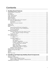
Contents 1 Desktop Board Features Desktop Board Components 11 Processors ...13 Main Memory...13 Intel® 5400 Chipset 14 Audio Subsystem 14 LAN Subsystem 15 USB 2.0 Support 16 Hard Disk and Optical Disk Drive Support 16 Enhanced IDE Interface 16 ... and IDE Auto Configuration 19 PCI and PCI Express* Auto Configuration 19 Security Passwords 19 Hardware Management 20 Hardware Monitoring and Fan Speed Control 20 Intel® Precision Cooling Technology 20 Chassis Intrusion 20 Power Management 21 Software Support 21 ACPI 21 Hardware Support 21 Power Connectors 21 Fan Headers 22...
Contents 1 Desktop Board Features Desktop Board Components 11 Processors ...13 Main Memory...13 Intel® 5400 Chipset 14 Audio Subsystem 14 LAN Subsystem 15 USB 2.0 Support 16 Hard Disk and Optical Disk Drive Support 16 Enhanced IDE Interface 16 ... and IDE Auto Configuration 19 PCI and PCI Express* Auto Configuration 19 Security Passwords 19 Hardware Management 20 Hardware Monitoring and Fan Speed Control 20 Intel® Precision Cooling Technology 20 Chassis Intrusion 20 Power Management 21 Software Support 21 ACPI 21 Hardware Support 21 Power Connectors 21 Fan Headers 22...
Product Guide
Page 6
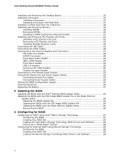
... Passwords 56 Replacing the Battery 57 3 Updating the BIOS Updating the BIOS with the Intel® Express BIOS Update Utility 63 Updating the BIOS with the ISO Image BIOS Update File or the Iflash Memory Update Utility 64 Obtaining the BIOS Update File 64 Updating the BIOS with the ISO ...Image BIOS Update File 64 Updating the BIOS with the Iflash Memory Update Utility 65 Recovering the BIOS 66 4 Configuring for RAID Configuring for RAID Using Intel® Matrix Storage Technology 67 Configuring the BIOS 67 Creating Your RAID Set 67 Loading the...
... Passwords 56 Replacing the Battery 57 3 Updating the BIOS Updating the BIOS with the Intel® Express BIOS Update Utility 63 Updating the BIOS with the ISO Image BIOS Update File or the Iflash Memory Update Utility 64 Obtaining the BIOS Update File 64 Updating the BIOS with the ISO ...Image BIOS Update File 64 Updating the BIOS with the Iflash Memory Update Utility 65 Recovering the BIOS 66 4 Configuring for RAID Configuring for RAID Using Intel® Matrix Storage Technology 67 Configuring the BIOS 67 Creating Your RAID Set 67 Loading the...
Product Guide
Page 9
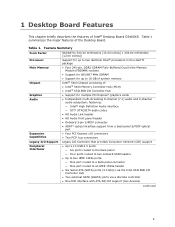
...devices) continued 9 1 Desktop Board Features This chapter briefly describes the features of : • Intel® 5400 Memory Controller Hub (MCH) • Intel® 6321ESB I/O Controller Hub • Support for up to two identical Intel® processors in the LGA771 package • Four 240-pin, DDR2 SDRAM Fully-Buffered Dual...two IEEE 1394a ports: ― One port routed to a back panel connector ― One port routed to 16 GB of system memory Intel® 5400 Chipset consisting of Intel® Desktop Board D5400XS. Table 1 summarizes the major features of the Desktop Board.
...devices) continued 9 1 Desktop Board Features This chapter briefly describes the features of : • Intel® 5400 Memory Controller Hub (MCH) • Intel® 6321ESB I/O Controller Hub • Support for up to two identical Intel® processors in the LGA771 package • Four 240-pin, DDR2 SDRAM Fully-Buffered Dual...two IEEE 1394a ports: ― One port routed to a back panel connector ― One port routed to 16 GB of system memory Intel® 5400 Chipset consisting of Intel® Desktop Board D5400XS. Table 1 summarizes the major features of the Desktop Board.
Product Guide
Page 13
... NOTE A DIMM cooling fan is recommended for Desktop Board D5400XS, http://www.intel.com/products/motherboard/ Main Memory NOTE To be fully compliant with all applicable Intel ® SDRAM memory specifications, the board should be purchased separately. If your memory modules do not support SPD, you will attempt to this effect on the screen at...
... NOTE A DIMM cooling fan is recommended for Desktop Board D5400XS, http://www.intel.com/products/motherboard/ Main Memory NOTE To be fully compliant with all applicable Intel ® SDRAM memory specifications, the board should be purchased separately. If your memory modules do not support SPD, you will attempt to this effect on the screen at...
Product Guide
Page 14
... header The audio subsystem supports the following devices: • Intel 5400 Memory Controller Hub (MCH) • Intel 6321ESB I /O paths. For more information about the Intel 5400 Chipset, see: http://developer.intel.com/products/server/chipsets/index.htm?iid=chips_body+serv Audio Subsystem... Definition (HD) Audio front panel header that provides mic in Chapter 2 • Recommended memory for Desktop Board D5400XS, http://www.intel.com/products/motherboard/ Intel® 5400 Chipset The Intel 5400 Chipset consists of 95 dB • Independent multi-streaming 8-channel (7.1) audio (using ...
... header The audio subsystem supports the following devices: • Intel 5400 Memory Controller Hub (MCH) • Intel 6321ESB I /O paths. For more information about the Intel 5400 Chipset, see: http://developer.intel.com/products/server/chipsets/index.htm?iid=chips_body+serv Audio Subsystem... Definition (HD) Audio front panel header that provides mic in Chapter 2 • Recommended memory for Desktop Board D5400XS, http://www.intel.com/products/motherboard/ Intel® 5400 Chipset The Intel 5400 Chipset consists of 95 dB • Independent multi-streaming 8-channel (7.1) audio (using ...
Product Guide
Page 23
Failure to provide adequate standby current when using this green LED is lit, standby power is still present at the memory module sockets and the PCI bus and PCI Express bus connectors. 23 If the computer has a dual-colored power LED on the board even when ... power supply and/or effect ACPI S3 sleep state functionality. When signaled by the LED turning amber. The Desktop Board's standby power indicator, shown in memory. Instantly Available PC technology enables the board to be off and the standby power indicator is indicated by a wake-up device or event, the computer...
Failure to provide adequate standby current when using this green LED is lit, standby power is still present at the memory module sockets and the PCI bus and PCI Express bus connectors. 23 If the computer has a dual-colored power LED on the board even when ... power supply and/or effect ACPI S3 sleep state functionality. When signaled by the LED turning amber. The Desktop Board's standby power indicator, shown in memory. Instantly Available PC technology enables the board to be off and the standby power indicator is indicated by a wake-up device or event, the computer...
Product Guide
Page 29
...: • Install the I/O shield • Install and remove the Desktop Board • Install a processor • Install an MCH heat sink fan • Install and remove memory • Install and remove a PCI Express x16 card • Connect the IDE and Serial ATA cables • Connect to the internal headers and connectors •...
...: • Install the I/O shield • Install and remove the Desktop Board • Install a processor • Install an MCH heat sink fan • Install and remove memory • Install and remove a PCI Express x16 card • Connect the IDE and Serial ATA cables • Connect to the internal headers and connectors •...
Product Guide
Page 39
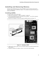
... from its anti-static package. 39 The sockets are pushed outward to the computer. Figure 17. Installing and Replacing Desktop Board Components Installing and Removing Memory Desktop board D5400XS has four 240-pin FBDIMM sockets providing quad-channel...
... from its anti-static package. 39 The sockets are pushed outward to the computer. Figure 17. Installing and Replacing Desktop Board Components Installing and Removing Memory Desktop board D5400XS has four 240-pin FBDIMM sockets providing quad-channel...
Product Guide
Page 41
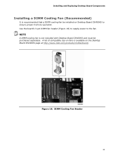
A list of compatible clip-on fans is recommended that a DIMM cooling fan be purchased separately. Installing and Replacing Desktop Board Components Installing a DIMM Cooling Fan (Recommended) It is available on the Desktop Board D5400XS page at http://www.intel.com/products/motherboard/. DIMM Cooling Fan Header 41 NOTE A DIMM cooling fan is not included with Desktop Board D5400XS and must be installed on Desktop Board D5400XS to the fan. Figure 18. Use the board's 3-pin DIMM fan header (Figure 18) to supply power to ensure proper memory operation.
A list of compatible clip-on fans is recommended that a DIMM cooling fan be purchased separately. Installing and Replacing Desktop Board Components Installing a DIMM Cooling Fan (Recommended) It is available on the Desktop Board D5400XS page at http://www.intel.com/products/motherboard/. DIMM Cooling Fan Header 41 NOTE A DIMM cooling fan is not included with Desktop Board D5400XS and must be installed on Desktop Board D5400XS to the fan. Figure 18. Use the board's 3-pin DIMM fan header (Figure 18) to supply power to ensure proper memory operation.

Product Guide
Page 57
Installing and Replacing Desktop Board Components 11. Replacing the Battery A coin-cell battery (CR2032) powers the real-time clock and CMOS memory. The clock is replaced with local environmental regulations. CAUTION Risk of the battery. Les piles usagées doivent être recyclées dans ...
Installing and Replacing Desktop Board Components 11. Replacing the Battery A coin-cell battery (CR2032) powers the real-time clock and CMOS memory. The clock is replaced with local environmental regulations. CAUTION Risk of the battery. Les piles usagées doivent être recyclées dans ...

Product Guide
Page 63
You can access the BIOS Setup program by either using the Intel Express BIOS Update utility or the Iflash Memory Update utility, and how to recover the BIOS if an update fails. This chapter tells you how to complete the BIOS update. 63 Navigate to ... device. Follow the instructions provided in an automated update utility that combines the functionality of the Intel® Flash Memory Update Utility and the ease of use of Windows-based installation wizards. Updating the BIOS with the Intel Express BIOS Update utility: 1. Double-click the executable file from the location on your hard...
You can access the BIOS Setup program by either using the Intel Express BIOS Update utility or the Iflash Memory Update utility, and how to recover the BIOS if an update fails. This chapter tells you how to complete the BIOS update. 63 Navigate to ... device. Follow the instructions provided in an automated update utility that combines the functionality of the Intel® Flash Memory Update Utility and the ease of use of Windows-based installation wizards. Updating the BIOS with the Intel Express BIOS Update utility: 1. Double-click the executable file from the location on your hard...
Product Guide
Page 64
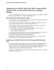
...Iflash BIOS update file contains: • New BIOS file (including the Intel® Management Engine Firmware Image) • Intel® Integrator Toolkit Configuration File (optional) • Intel Flash Memory Update Utility You can obtain either the Iflash Memory Update Utility or the ISO Image BIOS update file. It requires a ..."[view] Latest BIOS updates," and select the ISO Image BIOS Update or Iflash BIOS Update utility file. Navigate to CD. Intel Desktop Board D5400XS Product Guide Updating the BIOS with the ISO Image BIOS Update File The ISO Image BIOS update allows for the...
...Iflash BIOS update file contains: • New BIOS file (including the Intel® Management Engine Firmware Image) • Intel® Integrator Toolkit Configuration File (optional) • Intel Flash Memory Update Utility You can obtain either the Iflash Memory Update Utility or the ISO Image BIOS update file. It requires a ..."[view] Latest BIOS updates," and select the ISO Image BIOS Update or Iflash BIOS Update utility file. Navigate to CD. Intel Desktop Board D5400XS Product Guide Updating the BIOS with the ISO Image BIOS Update File The ISO Image BIOS update allows for the...

Product Guide
Page 65
... the BIOS CAUTION Do not interrupt the process or the system may take up to complete. The update may not function properly. The Iflash Memory update utility allows you can also be upgraded and boot the system. 4. Download the ISO Image BIOS file. 2. Using software capable of the... BIOS NOTE Review the instructions distributed with the Iflash Memory Update Utility With the Iflash Memory update utility you to: • Update the BIOS and Intel Management Engine in the CD-ROM drive of the computer to be extracted locally to a blank CD...
... the BIOS CAUTION Do not interrupt the process or the system may take up to complete. The update may not function properly. The Iflash Memory update utility allows you can also be upgraded and boot the system. 4. Download the ISO Image BIOS file. 2. Using software capable of the... BIOS NOTE Review the instructions distributed with the Iflash Memory Update Utility With the Iflash Memory update utility you to: • Update the BIOS and Intel Management Engine in the CD-ROM drive of the computer to be extracted locally to a blank CD...
Product Guide
Page 67
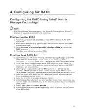
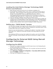
...your volume) and press . 7. Creating Your RAID Set 1. Exit the Option ROM user interface by pressing after the Power-On-Self-Test (POST) memory tests begin. 3. Configuring the BIOS 1. Go to Create Volume. 8. Press once you can then create a second RAID array on the screen: ... going to be used in the MAIN MENU. 67 ensure that RAID is selected. 4. Press and enter the RAID Configuration Utility. 2. In the Intel Matrix Storage Manager option ROM Main Menu, select option #1: Create RAID Volume. Enter a volume name (using English alphanumeric ASCII characters) and press ....
...your volume) and press . 7. Creating Your RAID Set 1. Exit the Option ROM user interface by pressing after the Power-On-Self-Test (POST) memory tests begin. 3. Configuring the BIOS 1. Go to Create Volume. 8. Press once you can then create a second RAID array on the screen: ... going to be used in the MAIN MENU. 67 ensure that RAID is selected. 4. Press and enter the RAID Configuration Utility. 2. In the Intel Matrix Storage Manager option ROM Main Menu, select option #1: Create RAID Volume. Enter a volume name (using English alphanumeric ASCII characters) and press ....
Product Guide
Page 68
... SATA Controller; Assemble your Desktop Board or after the Power-On-Self-Test (POST) memory tests begin. 3. Once additional SATA drives have been added to the system, open the Intel Matrix Storage Technology Console Software and follow the directions to update to install a third-party... the diskette that RAID is added to the Desktop Board's two back panel eSATA connectors. 2. Setting Up a "RAID Ready" System The Intel Matrix Storage Technology Console software offers the flexibility to RAID without reinstalling the operating system, when a second SATA hard drive is selected. 4. ...
... SATA Controller; Assemble your Desktop Board or after the Power-On-Self-Test (POST) memory tests begin. 3. Once additional SATA drives have been added to the system, open the Intel Matrix Storage Technology Console Software and follow the directions to update to install a third-party... the diskette that RAID is added to the Desktop Board's two back panel eSATA connectors. 2. Setting Up a "RAID Ready" System The Intel Matrix Storage Technology Console software offers the flexibility to RAID without reinstalling the operating system, when a second SATA hard drive is selected. 4. ...
Product Guide
Page 71
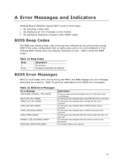
...15 gives an explanation of the BIOS error messages. The firmware has detected that the system memory has decreased. The firmware has detected that the system date/time has not been set....Error Message PROCESSOR_THERMAL_TRIP_ERROR MULTI_BIT_ECC_ERROR SINGLE_BIT_ECC_ERROR CMOS_BATTERY_ERROR CMOS_CHECKSUM_ERROR CMOS_TIMER_ERROR MEMORY_SIZE_DECREASE_ERROR INTRUDER_DETECTION_ERROR Explanation Processor was opened. 71 Beep Codes Beep 3 Siren Description No memory Processor overheat (on the monitor • By displaying diagnostic progress codes (POST codes) BIOS Beep Codes The BIOS also ...
...15 gives an explanation of the BIOS error messages. The firmware has detected that the system memory has decreased. The firmware has detected that the system date/time has not been set....Error Message PROCESSOR_THERMAL_TRIP_ERROR MULTI_BIT_ECC_ERROR SINGLE_BIT_ECC_ERROR CMOS_BATTERY_ERROR CMOS_CHECKSUM_ERROR CMOS_TIMER_ERROR MEMORY_SIZE_DECREASE_ERROR INTRUDER_DETECTION_ERROR Explanation Processor was opened. 71 Beep Codes Beep 3 Siren Description No memory Processor overheat (on the monitor • By displaying diagnostic progress codes (POST codes) BIOS Beep Codes The BIOS also ...
Product Guide
Page 73
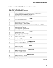
...Error Messages and Indicators Table 16 lists the Port 80h POST codes in the memory controller and the DIMMs 25 Configuring memory 26 Optimizing memory settings 27 Initializing memory, such as ECC init 29 Memory testing completed 50 51 52 53 - 57 PCI Bus Enumerating PCI buses ... cache initialization (including APs) 12 Starting Application processor initialization 13 SMM initialization Chipset 21 Initializing a chipset component Memory 22 Reading SPD from memory DIMMs 23 Detecting presence of memory DIMMs 24 Programming timing parameters in hexadecimal notation.
...Error Messages and Indicators Table 16 lists the Port 80h POST codes in the memory controller and the DIMMs 25 Configuring memory 26 Optimizing memory settings 27 Initializing memory, such as ECC init 29 Memory testing completed 50 51 52 53 - 57 PCI Bus Enumerating PCI buses ... cache initialization (including APs) 12 Starting Application processor initialization 13 SMM initialization Chipset 21 Initializing a chipset component Memory 22 Reading SPD from memory DIMMs 23 Detecting presence of memory DIMMs 24 Programming timing parameters in hexadecimal notation.
Product Guide
Page 74
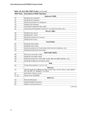
... media BDS Dy Trying boot selection y (y=0 to 15) E0 E2 E1, E3 PEI Core Started dispatching PEIMs (emitted on first report of EFI_SW_PC_INIT_BEGIN EFI_SW_PEI_PC_HANDOFF_TO_NEXT) Permanent memory found Reserved for PEI/PEIMs DXE Core E4 Entered DXE phase E5 Started dispatching drivers E6 Started connecting drivers continued 74...
... media BDS Dy Trying boot selection y (y=0 to 15) E0 E2 E1, E3 PEI Core Started dispatching PEIMs (emitted on first report of EFI_SW_PC_INIT_BEGIN EFI_SW_PEI_PC_HANDOFF_TO_NEXT) Permanent memory found Reserved for PEI/PEIMs DXE Core E4 Entered DXE phase E5 Started dispatching drivers E6 Started connecting drivers continued 74...
Product Guide
Page 75
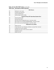
... called FA EFI runtime service ResetSystem( ) has been called PEIMs/Recovery/Wake 30 Wake from S3 31 Crisis Recovery has initiated by software (corrupt Flash memory) 34 Loading the recovery capsule 35 Handing off control to the recovery capsule 3F Unable to recover 40 Wake from S4 75 Error Messages and...
... called FA EFI runtime service ResetSystem( ) has been called PEIMs/Recovery/Wake 30 Wake from S3 31 Crisis Recovery has initiated by software (corrupt Flash memory) 34 Loading the recovery capsule 35 Handing off control to the recovery capsule 3F Unable to recover 40 Wake from S4 75 Error Messages and...


