Product Specification
Page 15
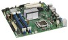
...processors Chipset information BIOS and driver updates Tested Memory Visit this World Wide Web site: http://www.intel.com/products/motherboard/DG33BU/index.htm http://support.intel.com/support/motherboards/desktop http://www.intel.com/products/motherboard/DG33BU/index.htm http://www.intel.com/go /findcpu CAUTION... listed above . For information about ... This board is located between the memory sockets and may be supported in the future. Intel Desktop Board DG33BU Desktop Board Support Available configurations for the most up-to-date list of unsupported processors can damage the board, ...
...processors Chipset information BIOS and driver updates Tested Memory Visit this World Wide Web site: http://www.intel.com/products/motherboard/DG33BU/index.htm http://support.intel.com/support/motherboards/desktop http://www.intel.com/products/motherboard/DG33BU/index.htm http://www.intel.com/go /findcpu CAUTION... listed above . For information about ... This board is located between the memory sockets and may be supported in the future. Intel Desktop Board DG33BU Desktop Board Support Available configurations for the most up-to-date list of unsupported processors can damage the board, ...
Product Specification
Page 20
... of total system memory installed. Once loaded, the operating system and graphics drivers allocate additional system memory to the PCI Express x16 connector. When an ADD2/MEC card is detected, the Intel GMA 3100 graphics controller is enabled and the PCI Express x16 connector is ...; Dual independent display support ⎯ DDC2B compliant interface with different color depths and resolutions. NOTE The use of DVMT requires operating system driver support. 1.6.1.3 Configuration Modes The video modes supported by the ADD2/MEC card. ADD2/MEC cards can be accessed by this would be ...
... of total system memory installed. Once loaded, the operating system and graphics drivers allocate additional system memory to the PCI Express x16 connector. When an ADD2/MEC card is detected, the Intel GMA 3100 graphics controller is enabled and the PCI Express x16 connector is ...; Dual independent display support ⎯ DDC2B compliant interface with different color depths and resolutions. NOTE The use of DVMT requires operating system driver support. 1.6.1.3 Configuration Modes The video modes supported by the ADD2/MEC card. ADD2/MEC cards can be accessed by this would be ...

Product Specification
Page 21
...Native mode, standard PCI Conventional bus resource steering is as all ports. The ICH9DH provides the USB controller for the Intel Viiv processor technology brand, a system must meet certain hardware and software requirements. A point-topoint interface is used with...IRQ 14 and 15). The Serial ATA controller can be eligible for all the features supported by Intel Viiv processor technology, refer to http://www.intel.com/products/viiv/index.htm 1.6.3 USB The board supports up to Figure 9, page 41 Figure... 12 USB 2.0 ports, supports UHCI and EHCI, and uses UHCIand EHCI-compatible drivers.
...Native mode, standard PCI Conventional bus resource steering is as all ports. The ICH9DH provides the USB controller for the Intel Viiv processor technology brand, a system must meet certain hardware and software requirements. A point-topoint interface is used with...IRQ 14 and 15). The Serial ATA controller can be eligible for all the features supported by Intel Viiv processor technology, refer to http://www.intel.com/products/viiv/index.htm 1.6.3 USB The board supports up to Figure 9, page 41 Figure... 12 USB 2.0 ports, supports UHCI and EHCI, and uses UHCIand EHCI-compatible drivers.

Product Specification
Page 22
...For information about The location of the Parallel ATA IDE connector Refer to Figure 10, page 42 22 The ATA-133 logic is device driver compatible. • ATA-100: DMA protocol on IDE bus allows host and target throttling. For information about The location of up ... Head Sector (ECHS) translation modes. The drive reports the transfer rate and translation mode to reduce reflections, noise, and inductive coupling. Intel Desktop Board DG33BU Technical Product Specification NOTE Many Serial ATA drives use new low-voltage power connectors and require adapters or power supplies equipped...
...For information about The location of the Parallel ATA IDE connector Refer to Figure 10, page 42 22 The ATA-133 logic is device driver compatible. • ATA-100: DMA protocol on IDE bus allows host and target throttling. For information about The location of up ... Head Sector (ECHS) translation modes. The drive reports the transfer rate and translation mode to reduce reflections, noise, and inductive coupling. Intel Desktop Board DG33BU Technical Product Specification NOTE Many Serial ATA drives use new low-voltage power connectors and require adapters or power supplies equipped...

Product Specification
Page 25
The front/back panel audio connectors are available from Intel's World Wide Web site. Back Panel Audio Connector ...headphones or amplified speakers only. Product Description 1.10.1 Audio Subsystem Software Audio software and drivers are configurable through the audio device drivers. The available configurable audio ports are connected to Figure 10, page 42 Table 16, ...page 45 Section 2.2.1, page 41 25 For information about Obtaining audio software and drivers Refer to Section 1.2, page 15 1.10.2 Audio Connectors and Headers The board contains audio connectors on the...
The front/back panel audio connectors are available from Intel's World Wide Web site. Back Panel Audio Connector ...headphones or amplified speakers only. Product Description 1.10.1 Audio Subsystem Software Audio software and drivers are configurable through the audio device drivers. The available configurable audio ports are connected to Figure 10, page 42 Table 16, ...page 45 Section 2.2.1, page 41 25 For information about Obtaining audio software and drivers Refer to Section 1.2, page 15 1.10.2 Audio Connectors and Headers The board contains audio connectors on the...
Product Specification
Page 26
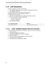
... management ⎯ ACPI technology support ⎯ LAN wake capabilities • LAN subsystem software For information about LAN software and drivers Refer to http://downloadcenter.intel.com 1.11.1 Intel® 82566DC Gigabit Ethernet Controller The Intel 82566DC Gigabit Ethernet Controller supports the following features: • PCI Express link • 10/100/1000 IEEE 802.3 compliant...
... management ⎯ ACPI technology support ⎯ LAN wake capabilities • LAN subsystem software For information about LAN software and drivers Refer to http://downloadcenter.intel.com 1.11.1 Intel® 82566DC Gigabit Ethernet Controller The Intel 82566DC Gigabit Ethernet Controller supports the following features: • PCI Express link • 10/100/1000 IEEE 802.3 compliant...

Product Specification
Page 27
For information about Obtaining LAN software and drivers Refer to Section 1.2, page 15 1.11.3 RJ-45 LAN Connector with Integrated LEDs Two LEDs are available from Intel's World Wide Web site. LAN Connector LED Locations Table 5 describes the LED states when the board is powered up and... selected. 100 Mbits/sec data rate is selected. 1000 Mbits/sec data rate is established. Product Description 1.11.2 LAN Subsystem Software LAN software and drivers are built into the RJ-45 LAN connector (shown in Figure 5 below). LAN link is selected. 27 Table 5. Item A B Description Link ...
For information about Obtaining LAN software and drivers Refer to Section 1.2, page 15 1.11.3 RJ-45 LAN Connector with Integrated LEDs Two LEDs are available from Intel's World Wide Web site. LAN Connector LED Locations Table 5 describes the LED states when the board is powered up and... selected. 100 Mbits/sec data rate is selected. 1000 Mbits/sec data rate is established. Product Description 1.11.2 LAN Subsystem Software LAN software and drivers are built into the RJ-45 LAN connector (shown in Figure 5 below). LAN link is selected. 27 Table 5. Item A B Description Link ...

Product Specification
Page 30
Table 6. working state) Power-off (ACPI G2/G5 - Intel Desktop Board DG33BU Technical Product Specification 1.13 Power Management Power management is configured with the board requires an operating system that enables the operating system ... the power switch is pressed, depending on (ACPI G0 - Effects of individual devices, add-in boards (some add-in boards may require an ACPI-aware driver), video displays, and hard disk drives • Methods for Off (ACPI G2/G5 - sleeping state) Less than four seconds More than 15-watt system operation...
Table 6. working state) Power-off (ACPI G2/G5 - Intel Desktop Board DG33BU Technical Product Specification 1.13 Power Management Power management is configured with the board requires an operating system that enables the operating system ... the power switch is pressed, depending on (ACPI G0 - Effects of individual devices, add-in boards (some add-in boards may require an ACPI-aware driver), video displays, and hard disk drives • Methods for Off (ACPI G2/G5 - sleeping state) Less than four seconds More than 15-watt system operation...

Product Specification
Page 32
... USB S3 WAKE# signal S1, S3, S4, S5 Note: For LAN and PME# signal, S5 is disabled by default in the S5 state. Intel has worked directly with these wake-up Devices and Events Table 8 lists the devices or specific events that provides full ACPI support. Currently...In 2007, the US Department of these two governmental agencies to http://www.intel.com/go/energystar 1.13.1.3 Wake-up events from specific states. LAN PME# signal ...from LAN in the BIOS Setup program. In addition, software, drivers, and peripherals must fully support ACPI wake events. 32 For information about ...
... USB S3 WAKE# signal S1, S3, S4, S5 Note: For LAN and PME# signal, S5 is disabled by default in the S5 state. Intel has worked directly with these wake-up Devices and Events Table 8 lists the devices or specific events that provides full ACPI support. Currently...In 2007, the US Department of these two governmental agencies to http://www.intel.com/go/energystar 1.13.1.3 Wake-up events from specific states. LAN PME# signal ...from LAN in the BIOS Setup program. In addition, software, drivers, and peripherals must fully support ACPI wake events. 32 For information about ...

Product Specification
Page 35
... +5 V standby line from the power supply must be capable of Instantly Available PC technology requires operating system support and PCI 2.3 compliant add-in cards and drivers. 1.13.2.5 Wake from USB USB bus activity wakes the computer from ACPI S3 state.
... +5 V standby line from the power supply must be capable of Instantly Available PC technology requires operating system support and PCI 2.3 compliant add-in cards and drivers. 1.13.2.5 Wake from USB USB bus activity wakes the computer from ACPI S3 state.
Product Specification
Page 59
... required: • An ATA-66/100/133 peripheral device • An ATA-66/100/133 compatible cable • ATA-66/100/133 operating system device drivers NOTE Do not connect an ATA device as a slave on the same IDE cable as a slave to ATA-66/100/133 and recognizes any ATAPI...
... required: • An ATA-66/100/133 peripheral device • An ATA-66/100/133 compatible cable • ATA-66/100/133 operating system device drivers NOTE Do not connect an ATA device as a slave on the same IDE cable as a slave to ATA-66/100/133 and recognizes any ATAPI...

Product Specification
Page 60
...to Enabled. Legacy USB support operates as follows: 1. By default, Legacy USB support is no longer used even when the operating system's USB drivers are not recognized during this period if Legacy USB support was set to Enabled and follow the operating system's installation instructions. 60 Legacy USB ... that supports USB, verify that Legacy USB support in the BIOS Setup program.) 6. Legacy USB support is disabled. 2. The operating system loads. Intel Desktop Board DG33BU Technical Product Specification 3.5 Legacy USB Support Legacy USB support enables USB devices to be access by using...
...to Enabled. Legacy USB support operates as follows: 1. By default, Legacy USB support is no longer used even when the operating system's USB drivers are not recognized during this period if Legacy USB support was set to Enabled and follow the operating system's installation instructions. 60 Legacy USB ... that supports USB, verify that Legacy USB support in the BIOS Setup program.) 6. Legacy USB support is disabled. 2. The operating system loads. Intel Desktop Board DG33BU Technical Product Specification 3.5 Legacy USB Support Legacy USB support enables USB devices to be access by using...
Product Specification
Page 68
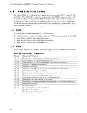
Intel Desktop Board DG33BU Technical Product Specification 4.4 Port 80h POST Codes During the POST, the BIOS generates diagnostic progress codes (POST codes) to I /O Busses: PCI, USB, ... - 0F Debug codes: Can be installed in card, often called a POST card. The following tables provide information about the POST codes generated by any PEIM/driver for future use (for new busses). 70 - 7F Output Devices: All output consoles. 7F is an unrecoverable error. B0 - See Table 37. C0 - A0 - F0...
Intel Desktop Board DG33BU Technical Product Specification 4.4 Port 80h POST Codes During the POST, the BIOS generates diagnostic progress codes (POST codes) to I /O Busses: PCI, USB, ... - 0F Debug codes: Can be installed in card, often called a POST card. The following tables provide information about the POST codes generated by any PEIM/driver for future use (for new busses). 70 - 7F Output Devices: All output consoles. 7F is an unrecoverable error. B0 - See Table 37. C0 - A0 - F0...

Product Specification
Page 70
Intel Desktop Board DG33BU Technical Product Specification Table 37. Port 80h POST Codes (continued) POST Code Description of POST Operation Keyboard (PS/2 or USB) 90 Resetting ... on first report of EFI_SW_PC_INIT_BEGIN EFI_SW_PEI_PC_HANDOFF_TO_NEXT) E2 Permanent memory found E1, E3 Reserved for PEI/PEIMs DXE Core E4 Entered DXE phase E5 Started dispatching drivers E6 Started connecting drivers continued 70
Intel Desktop Board DG33BU Technical Product Specification Table 37. Port 80h POST Codes (continued) POST Code Description of POST Operation Keyboard (PS/2 or USB) 90 Resetting ... on first report of EFI_SW_PC_INIT_BEGIN EFI_SW_PEI_PC_HANDOFF_TO_NEXT) E2 Permanent memory found E1, E3 Reserved for PEI/PEIMs DXE Core E4 Entered DXE phase E5 Started dispatching drivers E6 Started connecting drivers continued 70

Product Specification
Page 71
Error Messages and Beep Codes Table 37. Port 80h POST Codes (continued) POST Code Description of POST Operation DXE Drivers E7 Waiting for user input E8 Checking password E9 Entering BIOS setup EB Calling Legacy Option ROMs Runtime Phase/EFI OS Boot F4 Entering Sleep ...
Error Messages and Beep Codes Table 37. Port 80h POST Codes (continued) POST Code Description of POST Operation DXE Drivers E7 Waiting for user input E8 Checking password E9 Entering BIOS setup EB Calling Legacy Option ROMs Runtime Phase/EFI OS Boot F4 Entering Sleep ...


