Product Specification
Page 5
... 10 1.1.1 Feature Summary 10 1.1.2 Board Layout 12 1.1.3 Block Diagram 14 1.2 Online Support 15 1.3 Processor 15 1.4 System Memory 16 1.4.1 Memory Configurations 18 1.5 Intel® 945GC Chipset 21 1.5.1 Intel 945GC Graphics Subsystem 21 1.5.2 USB 23 1.5.3 IDE Support 24 1.5.4 Real-Time Clock, CMOS SRAM, ... 27 1.8.2 Audio Connectors 27 1.8.3 6-Channel (5.1) Audio Subsystem 28 1.9 LAN Subsystem 29 1.9.1 LAN Subsystem Software 29 1.9.2 Intel® 82562G Physical Layer Interface Device 29 1.10 Hardware Management Subsystem 31 1.10.1 Hardware Monitoring and Fan Control ASIC 31...
... 10 1.1.1 Feature Summary 10 1.1.2 Board Layout 12 1.1.3 Block Diagram 14 1.2 Online Support 15 1.3 Processor 15 1.4 System Memory 16 1.4.1 Memory Configurations 18 1.5 Intel® 945GC Chipset 21 1.5.1 Intel 945GC Graphics Subsystem 21 1.5.2 USB 23 1.5.3 IDE Support 24 1.5.4 Real-Time Clock, CMOS SRAM, ... 27 1.8.2 Audio Connectors 27 1.8.3 6-Channel (5.1) Audio Subsystem 28 1.9 LAN Subsystem 29 1.9.1 LAN Subsystem Software 29 1.9.2 Intel® 82562G Physical Layer Interface Device 29 1.10 Hardware Management Subsystem 31 1.10.1 Hardware Monitoring and Fan Control ASIC 31...
Product Specification
Page 8
...Color Power LED 56 27. DC Loading Characteristics 62 29. Boot Device Menu Options 74 35. Port 80h POST Codes 79 40. Processor Core Power Connector 53 23. Beep Codes 77 37. Port 80h POST Code Ranges 78 39. Environmental Specifications 67 32. Safety Regulations... Considerations for Components 66 31. Product Certification Markings 90 viii Intel Desktop Board D945GCCR Technical Product Specification 15. Front Panel Audio Header 52 17. Chassis Intrusion Header 52 18. Serial ATA Connectors 52 19. Processor Fan Header 52 20. Front and Rear Chassis Fan Headers...
...Color Power LED 56 27. DC Loading Characteristics 62 29. Boot Device Menu Options 74 35. Port 80h POST Codes 79 40. Processor Core Power Connector 53 23. Beep Codes 77 37. Port 80h POST Code Ranges 78 39. Environmental Specifications 67 32. Safety Regulations... Considerations for Components 66 31. Product Certification Markings 90 viii Intel Desktop Board D945GCCR Technical Product Specification 15. Front Panel Audio Header 52 17. Chassis Intrusion Header 52 18. Serial ATA Connectors 52 19. Processor Fan Header 52 20. Front and Rear Chassis Fan Headers...
Product Specification
Page 9
1 Product Description What This Chapter Contains 1.1 Overview 10 1.2 Online Support 15 1.3 Processor 15 1.4 System Memory 16 1.5 Intel® 945GC Chipset 21 1.6 PCI Express* Connectors 25 1.7 Legacy I/O Controller 26 1.8 Audio Subsystem 27 1.9 LAN Subsystem 29 1.10 Hardware Management Subsystem 31 1.11 Power Management 33 9
1 Product Description What This Chapter Contains 1.1 Overview 10 1.2 Online Support 15 1.3 Processor 15 1.4 System Memory 16 1.5 Intel® 945GC Chipset 21 1.6 PCI Express* Connectors 25 1.7 Legacy I/O Controller 26 1.8 Audio Subsystem 27 1.9 LAN Subsystem 29 1.10 Hardware Management Subsystem 31 1.11 Power Management 33 9
Product Specification
Page 10
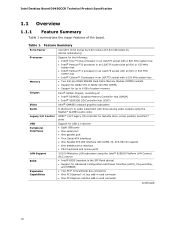
... (9.60 inches by 9.60 inches [243.84 millimeters by 243.84 millimeters]) Support for the following: • Intel® Core™2 Duo processor in an LGA775 socket with a 800 MHz system bus • Intel® Pentium® D processor in an LGA775 socket with an 800 or 533 MHz system bus •...; Intel® Pentium® 4 processor in an LGA775 socket with an 800 or 533 MHz system bus • Intel® Celeron® D processor in an LGA775 socket with UDMA 33, ATA-66/100 support • One diskette drive interface •...
... (9.60 inches by 9.60 inches [243.84 millimeters by 243.84 millimeters]) Support for the following: • Intel® Core™2 Duo processor in an LGA775 socket with a 800 MHz system bus • Intel® Pentium® D processor in an LGA775 socket with an 800 or 533 MHz system bus •...; Intel® Pentium® 4 processor in an LGA775 socket with an 800 or 533 MHz system bus • Intel® Celeron® D processor in an LGA775 socket with UDMA 33, ATA-66/100 support • One diskette drive interface •...
Product Specification
Page 13
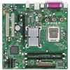
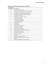
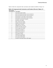
... connector #1 D PCI Express x1 bus add-in card connector E PCI Express x16 bus add-in card connector F Back panel connectors G Processor core power connector H Processor fan header I Rear chassis fan header J LGA775 processor socket K Intel 82945GC GMCH L DIMM socket M DIMM socket N Chassis intrusion header O Main Power connector P Diskette drive connector Q Parallel ATE IDE connector...
... connector #1 D PCI Express x1 bus add-in card connector E PCI Express x16 bus add-in card connector F Back panel connectors G Processor core power connector H Processor fan header I Rear chassis fan header J LGA775 processor socket K Intel 82945GC GMCH L DIMM socket M DIMM socket N Chassis intrusion header O Main Power connector P Diskette drive connector Q Parallel ATE IDE connector...
Product Specification
Page 15
... support the following processors: • Intel Core 2 Duo processor in an LGA775 socket with a 800 MHz system bus • Intel Pentium D processor in an LGA775 processor socket with an 800 or 533 MHz system bus • Intel Pentium 4 processor in an LGA775 processor socket with an 800 or 533 MHz system bus • Intel Celeron D processor in an LGA775 processor socket with...
... support the following processors: • Intel Core 2 Duo processor in an LGA775 socket with a 800 MHz system bus • Intel Pentium D processor in an LGA775 processor socket with an 800 or 533 MHz system bus • Intel Pentium 4 processor in an LGA775 processor socket with an 800 or 533 MHz system bus • Intel Celeron D processor in an LGA775 processor socket with...
Product Specification
Page 17
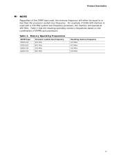
...Description NOTE Regardless of DIMMs and processors. Table 4 lists the resulting operating memory frequencies based on the combination of the DIMM type used with a 533 MHz system bus frequency processor, the memory will either be equal to or less than the processor system bus frequency. Memory Operating ...Frequencies DIMM Type DDR2 400 DDR2 400 DDR2 533 DDR2 533 Processor system bus frequency 533 MHz 800 MHz 533 ...
...Description NOTE Regardless of DIMMs and processors. Table 4 lists the resulting operating memory frequencies based on the combination of the DIMM type used with a 533 MHz system bus frequency processor, the memory will either be equal to or less than the processor system bus frequency. Memory Operating ...Frequencies DIMM Type DDR2 400 DDR2 400 DDR2 533 DDR2 533 Processor system bus frequency 533 MHz 800 MHz 533 ...
Product Specification
Page 24
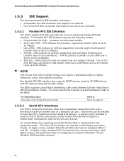
... supports a master/slave configuration and two devices per channel. In legacy mode, standard IDE I /O (PIO): processor controls data transfer. • 8237-style DMA: DMA offloads the processor, supporting transfer rates of up to 16 MB/sec. • Ultra DMA: DMA protocol on IDE bus supporting...and is transparent to 66 MB/sec. The Serial ATA controller can be installed on IDE bus allows host and target throttling. Intel Desktop Board D945GCCR Technical Product Specification 1.5.3 IDE Support The board provides five IDE interface connectors: • One parallel ATA IDE ...
... supports a master/slave configuration and two devices per channel. In legacy mode, standard IDE I /O (PIO): processor controls data transfer. • 8237-style DMA: DMA offloads the processor, supporting transfer rates of up to 16 MB/sec. • Ultra DMA: DMA protocol on IDE bus supporting...and is transparent to 66 MB/sec. The Serial ATA controller can be installed on IDE bus allows host and target throttling. Intel Desktop Board D945GCCR Technical Product Specification 1.5.3 IDE Support The board provides five IDE interface connectors: • One parallel ATA IDE ...
Product Specification
Page 31
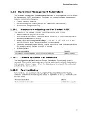
... monitoring and control (through the SMSC 5127 I /O controller used with the Wired for direct monitoring of processor temperature and ambient temperature sensing • Power supply monitoring of the fan headers Refer to be implemented using Intel® Desktop Utilities or third-party software. For information about The location of the fan headers...
... monitoring and control (through the SMSC 5127 I /O controller used with the Wired for direct monitoring of processor temperature and ambient temperature sensing • Power supply monitoring of the fan headers Refer to be implemented using Intel® Desktop Utilities or third-party software. For information about The location of the fan headers...
Product Specification
Page 32
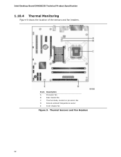
Item A B C D E Description Processor fan Rear chassis fan Thermal diode, located on processor die Remote ambient temperature sensor Front chassis fan Figure 9. Thermal Sensors and Fan Headers 32 Intel Desktop Board D945GCCR Technical Product Specification 1.10.4 Thermal Monitoring Figure 9 shows the location of the sensors and fan headers.
Item A B C D E Description Processor fan Rear chassis fan Thermal diode, located on processor die Remote ambient temperature sensor Front chassis fan Figure 9. Thermal Sensors and Fan Headers 32 Intel Desktop Board D945GCCR Technical Product Specification 1.10.4 Thermal Monitoring Figure 9 shows the location of the sensors and fan headers.
Product Specification
Page 34
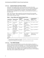
...working state. Full power > 30 W G1 - Suspend to disk. Suspend to the system. No power to disk. stop grant S3 - Processor stopped C1 - Soft off , but still connected to disk) states. no power for wake-up logic, except when provided by the board ...S4 (Suspend to AC power. Power States and Targeted System Power Global States Sleeping States Processor States Device States Targeted System Power (Note 1) G0 - sleeping state G2/S5 S1 - Intel Desktop Board D945GCCR Technical Product Specification 1.11.1.1 System States and Power States Under ACPI, ...
...working state. Full power > 30 W G1 - Suspend to disk. Suspend to the system. No power to disk. stop grant S3 - Processor stopped C1 - Soft off , but still connected to disk) states. no power for wake-up logic, except when provided by the board ...S4 (Suspend to AC power. Power States and Targeted System Power Global States Sleeping States Processor States Device States Targeted System Power (Note 1) G0 - sleeping state G2/S5 S1 - Intel Desktop Board D945GCCR Technical Product Specification 1.11.1.1 System States and Power States Under ACPI, ...
Product Specification
Page 36
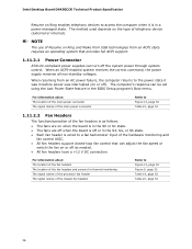
For information about The location of the fan headers The location of the fan headers and sensors for thermal monitoring The signal names of the processor fan header The signal names of the chassis fan headers Refer to a fan tachometer input of the fan headers is as needed. • All fan... an ACPI state requires an operating system that can be set using the Last Power State feature in the BIOS Setup program's Boot menu. Intel Desktop Board D945GCCR Technical Product Specification Resume on Ring enables telephony devices to the power state it is wired to Figure 13, page 50 Figure...
For information about The location of the fan headers The location of the fan headers and sensors for thermal monitoring The signal names of the processor fan header The signal names of the chassis fan headers Refer to a fan tachometer input of the fan headers is as needed. • All fan... an ACPI state requires an operating system that can be set using the Last Power State feature in the BIOS Setup program's Boot menu. Intel Desktop Board D945GCCR Technical Product Specification Resume on Ring enables telephony devices to the power state it is wired to Figure 13, page 50 Figure...
Product Specification
Page 51
... connector E PCI Express x16 bus add-in Figure 13. Technical Reference Table 15 lists the component-side connectors and headers identified in card connector F Processor core power connector G Processor fan header H Rear chassis fan header I Chassis intrusion header J Main power connector K Diskette drive connector L Parallel ATA IDE connector M Front chassis fan header...
... connector E PCI Express x16 bus add-in Figure 13. Technical Reference Table 15 lists the component-side connectors and headers identified in card connector F Processor core power connector G Processor fan header H Rear chassis fan header I Chassis intrusion header J Main power connector K Diskette drive connector L Parallel ATA IDE connector M Front chassis fan header...
Product Specification
Page 52
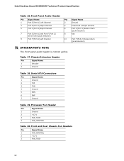
Intel Desktop Board D945GCCR Technical Product Specification Table 16. Processor Fan Header Pin Signal Name 1 Ground 2 +12 V 3 FAN_TACH 4 FAN_CONTROL Table 20. Front and Rear Chassis Fan Headers Pin Signal Name 1 FAN_CONTROL 2 +12 V 3 FAN_TACH 52 Table ...
Intel Desktop Board D945GCCR Technical Product Specification Table 16. Processor Fan Header Pin Signal Name 1 Ground 2 +12 V 3 FAN_TACH 4 FAN_CONTROL Table 20. Front and Rear Chassis Fan Headers Pin Signal Name 1 FAN_CONTROL 2 +12 V 3 FAN_TACH 52 Table ...
Product Specification
Page 53
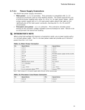
... previously used . The board supports the use a power supply with either 2 x 10 or 2 x 12 main power cables. Table 22. Processor Core Power Connector Pin Signal Name Pin 1 Ground 2 3 +12 V 4 Signal Name Ground +12 V 53 Failure to do so will ...12 V 3 Ground 15 Ground 4 +5 V 16 PS-ON# (power supply remote on Intel Desktop boards. Table 21. a 2 x 12 connector. a 2 x 2 connector. The 2 x 12 main power cable can provide up to the processor voltage regulator and must always be unconnected. When using high wattage PCI Express x16 graphics cards,...
... previously used . The board supports the use a power supply with either 2 x 10 or 2 x 12 main power cables. Table 22. Processor Core Power Connector Pin Signal Name Pin 1 Ground 2 3 +12 V 4 Signal Name Ground +12 V 53 Failure to do so will ...12 V 3 Ground 15 Ground 4 +5 V 16 PS-ON# (power supply remote on Intel Desktop boards. Table 21. a 2 x 12 connector. a 2 x 2 connector. The 2 x 12 main power cable can provide up to the processor voltage regulator and must always be unconnected. When using high wattage PCI Express x16 graphics cards,...
Product Specification
Page 58
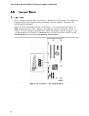
... of the Jumper Block 58 Table 27 describes the jumper settings for the three modes: normal, configure, and recovery. Otherwise, the board could be damaged. Intel Desktop Board D945GCCR Technical Product Specification 2.8 Jumper Block CAUTION Do not move the jumper with the power on. When the jumper is set to configure...
... of the Jumper Block 58 Table 27 describes the jumper settings for the three modes: normal, configure, and recovery. Otherwise, the board could be damaged. Intel Desktop Board D945GCCR Technical Product Specification 2.8 Jumper Block CAUTION Do not move the jumper with the power on. When the jumper is set to configure...
Product Specification
Page 62
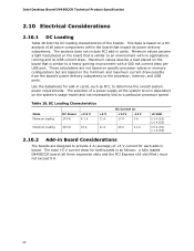
...-in board. Table 28. Minimum values assume a light load placed on the board that is based on specific processor values or memory configurations but are designed to determine the overall system power requirements. Intel Desktop Board D945GCCR Technical Product Specification 2.10 Electrical Considerations 2.10.1 DC Loading Table 28 lists the DC loading...
...-in board. Table 28. Minimum values assume a light load placed on the board that is based on specific processor values or memory configurations but are designed to determine the overall system power requirements. Intel Desktop Board D945GCCR Technical Product Specification 2.10 Electrical Considerations 2.10.1 DC Loading Table 28 lists the DC loading...
Product Specification
Page 63
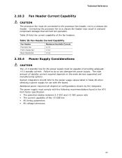
...for use with the following recommendations found in Table 28 when selecting a power supply for the power supply must be connected to the processor fan header, not to a chassis fan header may result in onboard component damage that will depend on the wake devices supported and ...• All voltage tolerances 63 The power supply must comply with the board. Technical Reference 2.10.3 Fan Header Current Capability CAUTION The processor fan must be capable of providing adequate +5 V standby current. System integrators should refer to do so can damage the power supply. Failure...
...for use with the following recommendations found in Table 28 when selecting a power supply for the power supply must be connected to the processor fan header, not to a chassis fan header may result in onboard component damage that will depend on the wake devices supported and ...• All voltage tolerances 63 The power supply must comply with the board. Technical Reference 2.10.3 Fan Header Current Capability CAUTION The processor fan must be capable of providing adequate +5 V standby current. System integrators should refer to do so can damage the power supply. Failure...
Product Specification
Page 64
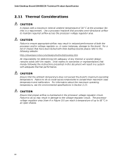
...voltage regulator or, in a system with a maximum internal ambient temperature of 38 oC at the processor fan inlet is maintained in the processor voltage regulator circuit. Intel Desktop Board D945GCCR Technical Product Specification 2.11 Thermal Considerations CAUTION A chassis with adequate thermal performance. ... with the reader. Failure to do so could cause components to the voltage regulator circuit. Use a processor heatsink that have been tested with Intel desktop boards please refer to the following the instructions presented in this document will result in some instances,...
...voltage regulator or, in a system with a maximum internal ambient temperature of 38 oC at the processor fan inlet is maintained in the processor voltage regulator circuit. Intel Desktop Board D945GCCR Technical Product Specification 2.11 Thermal Considerations CAUTION A chassis with adequate thermal performance. ... with the reader. Failure to do so could cause components to the voltage regulator circuit. Use a processor heatsink that have been tested with Intel desktop boards please refer to the following the instructions presented in this document will result in some instances,...
Product Specification
Page 65
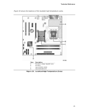
Localized High Temperature Zones 65 Technical Reference Figure 19 shows the locations of the localized high temperature zones. Item A B C D Description Processor voltage regulator area Processor Intel 82945GC GMCH Intel 82801GB ICH7 Figure 19.
Localized High Temperature Zones 65 Technical Reference Figure 19 shows the locations of the localized high temperature zones. Item A B C D Description Processor voltage regulator area Processor Intel 82945GC GMCH Intel 82801GB ICH7 Figure 19.


