
User Manual
Page 4
Intel® 945G Express Chipset Development Kit User's Manual Contents 4.4.1 4.4.2 4.4.3 4.4.4 4.4.5 4.4.6 4.4.7 4.4.8 4.4.9 4.5 Evaluation Board Headers 48 ATX Power Connectors 49 IDE Connector...50 SATA Pinout ...50 Fan Connectors...51 Front Panel USB ...945G/ICH7 Platform Block Diagram 11 Memory Channel and DIMM Configuration 27 Dual Channel (Interleaved) Mode Configuration with 2x DIMMs 27 Dual Channel (Interleaved) Mode Configuration with 3x DIMMs 27 Dual Channel (Interleaved) Mode Configuration with 4x DIMMs 28 Single Channel (Asymmetric) Mode Configuration with 1x DIMM 28 Single...
Intel® 945G Express Chipset Development Kit User's Manual Contents 4.4.1 4.4.2 4.4.3 4.4.4 4.4.5 4.4.6 4.4.7 4.4.8 4.4.9 4.5 Evaluation Board Headers 48 ATX Power Connectors 49 IDE Connector...50 SATA Pinout ...50 Fan Connectors...51 Front Panel USB ...945G/ICH7 Platform Block Diagram 11 Memory Channel and DIMM Configuration 27 Dual Channel (Interleaved) Mode Configuration with 2x DIMMs 27 Dual Channel (Interleaved) Mode Configuration with 3x DIMMs 27 Dual Channel (Interleaved) Mode Configuration with 4x DIMMs 28 Single Channel (Asymmetric) Mode Configuration with 1x DIMM 28 Single...

User Manual
Page 5
... that heat sink fan is pre installed. Initial release Reference #308823 5 Intel® 945G Express Chipset Development Kit User's Manual Contents Table 14 Table 15 Table 16...30 Table 31 Table 32 Back Panel I/O Connectors 41 Core Components ...42 Expansion Slots and Sockets 42 Intel® sDVO to PCI Express* Connector Mapping for MEC Cards 43 PCI Express* (x1) Pinout 45 ...47 Front Panel Jumper Setting 48 Evaluation Board Headers 48 2x12 ATX Power Connector 49 2x2 Auxiliary 12V Power Connector 49 IDE Connector...50 SATA Pinout ...50 Fan Connectors...51 Front Panel USB Header 51 Front...
... that heat sink fan is pre installed. Initial release Reference #308823 5 Intel® 945G Express Chipset Development Kit User's Manual Contents Table 14 Table 15 Table 16...30 Table 31 Table 32 Back Panel I/O Connectors 41 Core Components ...42 Expansion Slots and Sockets 42 Intel® sDVO to PCI Express* Connector Mapping for MEC Cards 43 PCI Express* (x1) Pinout 45 ...47 Front Panel Jumper Setting 48 Evaluation Board Headers 48 2x12 ATX Power Connector 49 2x2 Auxiliary 12V Power Connector 49 IDE Connector...50 SATA Pinout ...50 Fan Connectors...51 Front Panel USB Header 51 Front...

User Manual
Page 11
... Mb/s IDE DMI Interface Power Management Clock Generation 4 SATA Ports AC '97 / Intel® High Definition Audio CODECs PCI Express* x1 Intel® ICH7 Family LAN Connect System Management (TCO) SMBus 2.0 / I2C* PCI Bus GPIO Other ASICs (Optional) TPM (Optional) LPC Interface Super I /O subsystem. Intel® 945G Express Chipset Development Kit User's Manual Development Kit...
... Mb/s IDE DMI Interface Power Management Clock Generation 4 SATA Ports AC '97 / Intel® High Definition Audio CODECs PCI Express* x1 Intel® ICH7 Family LAN Connect System Management (TCO) SMBus 2.0 / I2C* PCI Bus GPIO Other ASICs (Optional) TPM (Optional) LPC Interface Super I /O subsystem. Intel® 945G Express Chipset Development Kit User's Manual Development Kit...

User Manual
Page 12
...-wire management of out-of-band networked systems regardless of the Intel® 945G Express Platform Features 800/533 MHz FSB PCI Express Interface Intel® Graphics Media Accelerator (GMA) 950 Intel® High Definition Audio Intel® Matrix Storage Technology Intel® Active Management Technology Serial ATA (SATA-II) 1.5/3 Gb/s Dual Channel DDR2, 533/667 MHz...
...-wire management of out-of-band networked systems regardless of the Intel® 945G Express Platform Features 800/533 MHz FSB PCI Express Interface Intel® Graphics Media Accelerator (GMA) 950 Intel® High Definition Audio Intel® Matrix Storage Technology Intel® Active Management Technology Serial ATA (SATA-II) 1.5/3 Gb/s Dual Channel DDR2, 533/667 MHz...

User Manual
Page 13
... Mbit, 512 Mbit, or 1 Gbit technology Intel® 945G Express Chipset, consisting of: • Intel® 82945G Graphics Memory Controller Hub ((G)MCH) • Intel® 82801GB I/O Controller Hub 7 (ICH7)... Option of either using the Realtek* ALC882 audio codec. depending on the media expansion card features. Development Kit Features Summary Form Factor Processor Memory Chipset Video Audio Legacy I /O controller for diskette drive, serial, parallel, and PS/2 ports Peripheral Interfaces LAN Support BIOS Expansion Capabilities Four SATA...
... Mbit, 512 Mbit, or 1 Gbit technology Intel® 945G Express Chipset, consisting of: • Intel® 82945G Graphics Memory Controller Hub ((G)MCH) • Intel® 82801GB I/O Controller Hub 7 (ICH7)... Option of either using the Realtek* ALC882 audio codec. depending on the media expansion card features. Development Kit Features Summary Form Factor Processor Memory Chipset Video Audio Legacy I /O controller for diskette drive, serial, parallel, and PS/2 ports Peripheral Interfaces LAN Support BIOS Expansion Capabilities Four SATA...

User Manual
Page 20
...concurrent). Serial ATA (SATA) Controller The ICH7 has an integrated SATA host controller that supports up to the LPC bridge interface function, D31:F0 contains other functional units including DMA, interrupt ...contains the legacy mode using I/O space operation. The ICH7's IDE system contains a single, independent IDE signal channel that can be electrically isolated. Universal Serial Bus (USB) ... (EHCI) host controller that support USB full-speed and low-speed signaling. Intel® 945G Express Chipset Development Kit User's Manual Development Kit Features PCI Express* Interface The...
...concurrent). Serial ATA (SATA) Controller The ICH7 has an integrated SATA host controller that supports up to the LPC bridge interface function, D31:F0 contains other functional units including DMA, interrupt ...contains the legacy mode using I/O space operation. The ICH7's IDE system contains a single, independent IDE signal channel that can be electrically isolated. Universal Serial Bus (USB) ... (EHCI) host controller that support USB full-speed and low-speed signaling. Intel® 945G Express Chipset Development Kit User's Manual Development Kit Features PCI Express* Interface The...

User Manual
Page 23
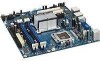
... chassis, take extra precaution when handling and operating the system. 3.2 Additional Hardware and Software Required Before you set up to four SATA drives and two IDE devices (master and slave) to the industry standard PCI Express x16 connector. Please refer to use any standard...board. Note: The MEC connector is provided on the back panel of a baseboard populated with one Intel® Pentium® 4 Processor 551 with HT Technology†, the Intel® 945G Express Chipset, and other system board components and peripheral connectors. Keyboard You will need a PS/2 style...
... chassis, take extra precaution when handling and operating the system. 3.2 Additional Hardware and Software Required Before you set up to four SATA drives and two IDE devices (master and slave) to the industry standard PCI Express x16 connector. Please refer to use any standard...board. Note: The MEC connector is provided on the back panel of a baseboard populated with one Intel® Pentium® 4 Processor 551 with HT Technology†, the Intel® 945G Express Chipset, and other system board components and peripheral connectors. Keyboard You will need a PS/2 style...

User Manual
Page 24
... Once the hardware described in a protective chassis, use of a standard desktop ATX power supply with the basic concepts involved in a static-free environment before removing any ...items are familiar with a minimum of your evaluation board. Install a SATA or IDE hard disk drive. 7. Contact your sales representative if any components from ...may cause product failure or unpredictable operation. 2. Populate hardware component to the board. Intel® 945G Express Chipset Development Kit User's Manual Setting Up the Development Kit Power Supply The...
... Once the hardware described in a protective chassis, use of a standard desktop ATX power supply with the basic concepts involved in a static-free environment before removing any ...items are familiar with a minimum of your evaluation board. Install a SATA or IDE hard disk drive. 7. Contact your sales representative if any components from ...may cause product failure or unpredictable operation. 2. Populate hardware component to the board. Intel® 945G Express Chipset Development Kit User's Manual Setting Up the Development Kit Power Supply The...

User Manual
Page 34
...11 12 13 Chipset 21 Memory 22 23 24 25 26 27 28 PCI Bus 50 51 52 53-57 USB 58 59 ATA/ATAPI/SATA 5A 5B SMBus 5C 5D Local Console 70 71 Description of POST Operation Power-on initialization of memory DIMMs. Programming timing parameters in memory... controller and DIMMs. Configuring memory. SMM initialization. Resetting PATA/SATA bus and all devices. Intel® 945G Express Chipset Development Kit User's Manual Setting Up the Development Kit Table 11 Range E0-FF / F0-FF E0 - Miscellaneous codes. ...
...11 12 13 Chipset 21 Memory 22 23 24 25 26 27 28 PCI Bus 50 51 52 53-57 USB 58 59 ATA/ATAPI/SATA 5A 5B SMBus 5C 5D Local Console 70 71 Description of POST Operation Power-on initialization of memory DIMMs. Programming timing parameters in memory... controller and DIMMs. Configuring memory. SMM initialization. Resetting PATA/SATA bus and all devices. Intel® 945G Express Chipset Development Kit User's Manual Setting Up the Development Kit Table 11 Range E0-FF / F0-FF E0 - Miscellaneous codes. ...

User Manual
Page 37
Resetting PATA/SATA bus and all devices. Reference #308823 37 Intel® 945G Express Chipset Development Kit User's Manual Setting Up the Development Kit POST EB 58 5A 92 90 94 5A 28 90 94 E7 01 00 Code Description Calling video BIOS. Resetting keyboard. Testing memory. Clearing keyboard input buffer. Waiting for user input. INT 19. Resetting keyboard. Ready to boot. Clearing keyboard input buffer. Resetting USB bus. Detecting the presence of the keyboard. Resetting PATA/SATA bus and all devices.
Resetting PATA/SATA bus and all devices. Reference #308823 37 Intel® 945G Express Chipset Development Kit User's Manual Setting Up the Development Kit POST EB 58 5A 92 90 94 5A 28 90 94 E7 01 00 Code Description Calling video BIOS. Resetting keyboard. Testing memory. Clearing keyboard input buffer. Waiting for user input. INT 19. Resetting keyboard. Ready to boot. Clearing keyboard input buffer. Resetting USB bus. Detecting the presence of the keyboard. Resetting PATA/SATA bus and all devices.

User Manual
Page 48
Comments 6-8: power up and reset. Intel® 945G Express Chipset Development Kit User's Manual Hardware References Figure 14 Front Panel Header Table 22 Front Panel Jumper Setting Reference Designators J7J2 Description Jumper used ... J2J1 J3B2 J5J3 J6J1 J6J2 J6H3 J6H4 J5J1 J1F2 J4B1 J3J1 J7J2 J7H2 J6A2 J6B2 J6H2 J2B1 Description 2x12 ATX power connector 2x2 Auxiliary 12V power connector IDE connector SATA connector SATA connector SATA connector SATA connector Chassis fan connector Chassis fan connector CPU fan connector Floppy drive connector Front panel header Front panel USB...
Comments 6-8: power up and reset. Intel® 945G Express Chipset Development Kit User's Manual Hardware References Figure 14 Front Panel Header Table 22 Front Panel Jumper Setting Reference Designators J7J2 Description Jumper used ... J2J1 J3B2 J5J3 J6J1 J6J2 J6H3 J6H4 J5J1 J1F2 J4B1 J3J1 J7J2 J7H2 J6A2 J6B2 J6H2 J2B1 Description 2x12 ATX power connector 2x2 Auxiliary 12V power connector IDE connector SATA connector SATA connector SATA connector SATA connector Chassis fan connector Chassis fan connector CPU fan connector Floppy drive connector Front panel header Front panel USB...

User Manual
Page 50
Intel® 945G Express Chipset Development Kit User's Manual Hardware References 4.4.3 Table 26 IDE Connector IDE Connector 4.4.4 Table 27 SATA Pinout SATA Pinout Pin Signal 1 GND 2 TXP 3 TXN 4 GND 5 RXN 6 RXP 7 GND 50 Reference #308823
Intel® 945G Express Chipset Development Kit User's Manual Hardware References 4.4.3 Table 26 IDE Connector IDE Connector 4.4.4 Table 27 SATA Pinout SATA Pinout Pin Signal 1 GND 2 TXP 3 TXN 4 GND 5 RXN 6 RXP 7 GND 50 Reference #308823


