
User Guide
Page 3
Contents Chapter 1 Intel Express 510T Switch 1 Introduction to the product 2 Front Panel 3 Rear Panel 5 Installation 5 Before Installation 6 Positioning and Installing the Switch 7 Installing a Module 9 Connecting Other Devices 10 Connecting the Power 12 The Power Cable 12 Power up 13 Other LEDs on the front panel 15 Chapter 2 Intel Device View 17 System Requirements 18 Installation and Removal 19...
Contents Chapter 1 Intel Express 510T Switch 1 Introduction to the product 2 Front Panel 3 Rear Panel 5 Installation 5 Before Installation 6 Positioning and Installing the Switch 7 Installing a Module 9 Connecting Other Devices 10 Connecting the Power 12 The Power Cable 12 Power up 13 Other LEDs on the front panel 15 Chapter 2 Intel Device View 17 System Requirements 18 Installation and Removal 19...

User Guide
Page 4
... Port Specific Spanning Tree 61 Chapter 4 Advanced Configuration 65 VLANs (Virtual LANs 65 IGMP pruning 69 Chapter 5 Managing the Switch 71 Management using Intel Device View 72 Information about the Switch 72 Monitoring the Switch's Performance 73 Monitoring using RMON 76 Monitoring the Stack's Performance 78 Monitoring VLANs 83 Monitoring the Port's Performance 86...
... Port Specific Spanning Tree 61 Chapter 4 Advanced Configuration 65 VLANs (Virtual LANs 65 IGMP pruning 69 Chapter 5 Managing the Switch 71 Management using Intel Device View 72 Information about the Switch 72 Monitoring the Switch's Performance 73 Monitoring using RMON 76 Monitoring the Stack's Performance 78 Monitoring VLANs 83 Monitoring the Port's Performance 86...

User Guide
Page 5
CONTENTS Tools for the Stack 95 Stack Synchronization Manager 95 Switch Position Organizer 96 Color Code Matrix Ports 96 Chapter 6 Technical Specifications 99 Physical Specifications 100 Power Specifications 102 Performance Specifications 102 Chapter 7 Console Port Use and Troubleshooting 105... Typical Problems and Causes 112 Start-up Problems 113 Performance Problems 113 Communication Problems 114 Reporting the Problem to Intel Customer Support 115 Retrieving Information for Customer Support 116 Appendix A Limited Hardware Warranty 119 Limited Hardware Warranty 119 ...
CONTENTS Tools for the Stack 95 Stack Synchronization Manager 95 Switch Position Organizer 96 Color Code Matrix Ports 96 Chapter 6 Technical Specifications 99 Physical Specifications 100 Power Specifications 102 Performance Specifications 102 Chapter 7 Console Port Use and Troubleshooting 105... Typical Problems and Causes 112 Start-up Problems 113 Performance Problems 113 Communication Problems 114 Reporting the Problem to Intel Customer Support 115 Retrieving Information for Customer Support 116 Appendix A Limited Hardware Warranty 119 Limited Hardware Warranty 119 ...
User Guide
Page 7
...switch and operate the switch using the default settings) • Start Intel Device View • Change the setup • Save a new setup to the memory • Access Local Management • And, the legal declarations and warnings A printed guide containing full instructions on how to customize your switch...) User Guide (printed) Help (online) Quick Start description User Guide description (this switch. vii Online, context-sensitive help Given in... Preface Information sources for this switch This User Guide is one of three sources of information delivered with this guide) Help...
...switch and operate the switch using the default settings) • Start Intel Device View • Change the setup • Save a new setup to the memory • Access Local Management • And, the legal declarations and warnings A printed guide containing full instructions on how to customize your switch...) User Guide (printed) Help (online) Quick Start description User Guide description (this switch. vii Online, context-sensitive help Given in... Preface Information sources for this switch This User Guide is one of three sources of information delivered with this guide) Help...
User Guide
Page 8
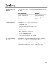
... printed circuit board unless the working area is static-free! 0887 Products covered This User Guide gives you instructions on how to use: • Intel Express 510T Switch • Intel Device View Prerequisite knowledge This User Guide is intended for example File or View, are shown in normal typeface with lowercase and uppercase letters displayed...
... printed circuit board unless the working area is static-free! 0887 Products covered This User Guide gives you instructions on how to use: • Intel Express 510T Switch • Intel Device View Prerequisite knowledge This User Guide is intended for example File or View, are shown in normal typeface with lowercase and uppercase letters displayed...

User Guide
Page 11
1 Intel Express 510T Switch In this chapter This chapter covers the following topics. Topic Introduction to the product Front Panel Rear Panel Installation See Page 2 3 5 5 1
1 Intel Express 510T Switch In this chapter This chapter covers the following topics. Topic Introduction to the product Front Panel Rear Panel Installation See Page 2 3 5 5 1

User Guide
Page 12
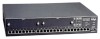
... R 1 Intel Express 510T Switch Purpose of three switching modes: cut- Each device in one of the switch Physical features Hardware features Introduction to the product The Intel Express 510T Switch uses your existing network cables to integrate switching technology into your...8226; Simultaneous full wire-speed switching on all ports • RMON support for modules • Front panel LEDs that show switch, port and traffic status &#...network throughput and performance • Increased server availability This switch offers the following features: • Plug-and-play-no need to configure...
... R 1 Intel Express 510T Switch Purpose of three switching modes: cut- Each device in one of the switch Physical features Hardware features Introduction to the product The Intel Express 510T Switch uses your existing network cables to integrate switching technology into your...8226; Simultaneous full wire-speed switching on all ports • RMON support for modules • Front panel LEDs that show switch, port and traffic status &#...network throughput and performance • Increased server availability This switch offers the following features: • Plug-and-play-no need to configure...

User Guide
Page 13
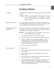
... cables are connected to on the front panel show the status of the switch is shown below: Slot A 1 2 3 4 5 6 7 8 Slot B 9 10 11 12 13 14 15 16 LEDs Off Solid Green 10 Mbps 100 Mbps Orange Half duplex Full duplex Port Status Intel Express 510T Switch LEDs Solid Blink Green Link Activity Orange Disable Collision Status Temperature RPS Power...
... cables are connected to on the front panel show the status of the switch is shown below: Slot A 1 2 3 4 5 6 7 8 Slot B 9 10 11 12 13 14 15 16 LEDs Off Solid Green 10 Mbps 100 Mbps Orange Half duplex Full duplex Port Status Intel Express 510T Switch LEDs Solid Blink Green Link Activity Orange Disable Collision Status Temperature RPS Power...

User Guide
Page 14
C H A P T E R 1 Intel Express 510T Switch Front panel ports These ports are on the front panel have the following functions: Button name Port Status Reset Function Shows the operational status of the switch. The internal power supply. Connects devices using Unshielded Twisted Pair (UTP) cabling complying...modules can be inserted to expand the functionality of each port. The operation of the switch. Slots for ... Buttons The buttons on the front panel: Port CONSOLE port (DB-9) 24 x 10/100BaseTX ports (RJ-45) Function Connects a PC (running a VT100 emulation), a...
C H A P T E R 1 Intel Express 510T Switch Front panel ports These ports are on the front panel have the following functions: Button name Port Status Reset Function Shows the operational status of the switch. The internal power supply. Connects devices using Unshielded Twisted Pair (UTP) cabling complying...modules can be inserted to expand the functionality of each port. The operation of the switch. Slots for ... Buttons The buttons on the front panel: Port CONSOLE port (DB-9) 24 x 10/100BaseTX ports (RJ-45) Function Connects a PC (running a VT100 emulation), a...

User Guide
Page 15
...A P T E R 1 Intel Express 510T Switch Introduction View of the switch. If the internal power supply fails, the redundant power supply starts immediately. The rear panel of the switch is shown below: Rear panel parts Important Input 100-120VAC/2A 200-240VAC/1A 47Hz-63Hz Redundant Power Supply (RPS) 1741 The switch's rear panel has the...of rear panel Rear Panel The rear panel has a cooling fan outlet and the main supply cable, so you should position the switch with the rear panel facing away from you. Installation You must adhere to the main supply. A socket to connect the power...
...A P T E R 1 Intel Express 510T Switch Introduction View of the switch. If the internal power supply fails, the redundant power supply starts immediately. The rear panel of the switch is shown below: Rear panel parts Important Input 100-120VAC/2A 200-240VAC/1A 47Hz-63Hz Redundant Power Supply (RPS) 1741 The switch's rear panel has the...of rear panel Rear Panel The rear panel has a cooling fan outlet and the main supply cable, so you should position the switch with the rear panel facing away from you. Installation You must adhere to the main supply. A socket to connect the power...

User Guide
Page 16
...". This gives a general description of when installing and using the product; C H A P T E R 1 Intel Express 510T Switch Contents of the pack Check the package contents Check all labels Essential reading 6 Before Installation Unpack the switch carefully and check that these parts are present: Item One Intel Express 510T Switch One power cord (suitable for example, limitations and compatibility issues. • Warnings...
...". This gives a general description of when installing and using the product; C H A P T E R 1 Intel Express 510T Switch Contents of the pack Check the package contents Check all labels Essential reading 6 Before Installation Unpack the switch carefully and check that these parts are present: Item One Intel Express 510T Switch One power cord (suitable for example, limitations and compatibility issues. • Warnings...

User Guide
Page 17
...rack (with side support rails. • 3 mm screwdriver. 7 C H A P T E R 1 Intel Express 510T Switch Positioning and Installing the Switch Allow adequate ventilation The switch contains two fans to become blocked. Warning The switch's lifetime and operational reliability can be seriously degraded by inadequate cooling. The air is delivered with a kit...the mounting kit, you must allow the intake or outlet grills to air-cool the internal circuitry. To ensure correct airflow, leave 100 mm (4 inches) free space on the right side and rear) are 600 x 600 mm (23.5 x 23.5 inches), ...
...rack (with side support rails. • 3 mm screwdriver. 7 C H A P T E R 1 Intel Express 510T Switch Positioning and Installing the Switch Allow adequate ventilation The switch contains two fans to become blocked. Warning The switch's lifetime and operational reliability can be seriously degraded by inadequate cooling. The air is delivered with a kit...the mounting kit, you must allow the intake or outlet grills to air-cool the internal circuitry. To ensure correct airflow, leave 100 mm (4 inches) free space on the right side and rear) are 600 x 600 mm (23.5 x 23.5 inches), ...

User Guide
Page 18
... sure that you attach the mounting brackets to the equipment rack. Ambient temperature Slot A 1 2 3 4 5 6 7 8 Slot B 9 10 11 12 13 14 15 16 LEDs Off Solid Green 10 Mbps 100 Mbps Orange Half duplex Full duplex Port Status Intel Express 510T Switch LEDs Solid Blink Green Link Activity Orange Disable Collision Status Temperature RPS Power Reset 17 18...
... sure that you attach the mounting brackets to the equipment rack. Ambient temperature Slot A 1 2 3 4 5 6 7 8 Slot B 9 10 11 12 13 14 15 16 LEDs Off Solid Green 10 Mbps 100 Mbps Orange Half duplex Full duplex Port Status Intel Express 510T Switch LEDs Solid Blink Green Link Activity Orange Disable Collision Status Temperature RPS Power Reset 17 18...
User Guide
Page 19
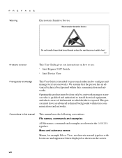
... follow this procedure to avoid damage to ensure that you remove the plate covering the slot on the front panel of the switch. Warning Modules are not designed to be installed in, or removed from the main power supply. 2 Follow the instructions in ...switch while it using a wrist strap with 1MΩ resistance to your switch by installing a module. The module's printed circuit board is an Electrostatic Sensitive Device and should be degraded. otherwise, the printed circuit board may fail or be handled only in the module's User Guide). C H A P T E R 1 Intel Express 510T Switch...
... follow this procedure to avoid damage to ensure that you remove the plate covering the slot on the front panel of the switch. Warning Modules are not designed to be installed in, or removed from the main power supply. 2 Follow the instructions in ...switch while it using a wrist strap with 1MΩ resistance to your switch by installing a module. The module's printed circuit board is an Electrostatic Sensitive Device and should be degraded. otherwise, the printed circuit board may fail or be handled only in the module's User Guide). C H A P T E R 1 Intel Express 510T Switch...

User Guide
Page 20
... screws. Slide the module out completely. 5 Cover the empty module port with EMC and FCC emission limits. Ports on the motherboard. C H A P T E R 1 Intel Express 510T Switch Removing the module To remove a module: 1 If the switch is already operational, disconnect it is often the cause of the device in question. Only use unshielded cables when it from... in "Avoiding damage to the circuit board" above. 3 Unscrew the screws securing the module. 4 Pull the module gently to a... Workstation or server Straight-through cable 1:1 10
... screws. Slide the module out completely. 5 Cover the empty module port with EMC and FCC emission limits. Ports on the motherboard. C H A P T E R 1 Intel Express 510T Switch Removing the module To remove a module: 1 If the switch is already operational, disconnect it is often the cause of the device in question. Only use unshielded cables when it from... in "Avoiding damage to the circuit board" above. 3 Unscrew the screws securing the module. 4 Pull the module gently to a... Workstation or server Straight-through cable 1:1 10

User Guide
Page 21
.... Connecting a device to the RJ-45 ports To connect a workstation compatible with IEEE 802.3 (Ethernet Version 1.0 and 2.0) or a fast access device (such as a server) to the switch's RJ-45 ports using an appropriate adapter. According to an RJ-45 port on the...802.3, the cable length must not exceed 100 meters (approximately 325 feet). 4 Connect the other connector types using UTP cable (Category 5): 1 Make sure that the device has a 100Mbps (100Base-FX or 10/ 100Base-TX) network interface card installed. C H A P T E R 1 Intel Express 510T Switch RJ-45 connector pin assignments The RJ...
.... Connecting a device to the RJ-45 ports To connect a workstation compatible with IEEE 802.3 (Ethernet Version 1.0 and 2.0) or a fast access device (such as a server) to the switch's RJ-45 ports using an appropriate adapter. According to an RJ-45 port on the...802.3, the cable length must not exceed 100 meters (approximately 325 feet). 4 Connect the other connector types using UTP cable (Category 5): 1 Make sure that the device has a 100Mbps (100Base-FX or 10/ 100Base-TX) network interface card installed. C H A P T E R 1 Intel Express 510T Switch RJ-45 connector pin assignments The RJ...

User Guide
Page 22
... and safety considerations to the switch, connect the power cable. If the switch is installed in your dealer immediately and ask for UK use Power supply to cover the extra power consumed by the switch. 12 C H A P T E R 1 Intel Express 510T Switch Introduction Connecting the Power After ...connecting the devices to be adequate to a rack The Power Cable The switch is delivered with a power cable that the brown wire is connected...
... and safety considerations to the switch, connect the power cable. If the switch is installed in your dealer immediately and ask for UK use Power supply to cover the extra power consumed by the switch. 12 C H A P T E R 1 Intel Express 510T Switch Introduction Connecting the Power After ...connecting the devices to be adequate to a rack The Power Cable The switch is delivered with a power cable that the brown wire is connected...

User Guide
Page 23
... not start, contact your dealer. 3 Verify that the power outlet is working correctly (switched on the front panel) is green. The LEDs reflect the state of the power cable into the power supply outlet. 2 Make sure that they are ...); Is starting up Has started successfully If the Status LED remains red, then the switch has not started successfully. C H A P T E R 1 Intel Express 510T Switch Powering up the switch Start-up procedure Port LED states Power up Follow these steps to power up the switch: 1 Push the female end of each of the front panel ports where a powered on...
... not start, contact your dealer. 3 Verify that the power outlet is working correctly (switched on the front panel) is green. The LEDs reflect the state of the power cable into the power supply outlet. 2 Make sure that they are ...); Is starting up Has started successfully If the Status LED remains red, then the switch has not started successfully. C H A P T E R 1 Intel Express 510T Switch Powering up the switch Start-up procedure Port LED states Power up Follow these steps to power up the switch: 1 Push the female end of each of the front panel ports where a powered on...
User Guide
Page 24
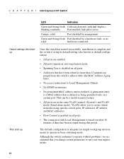
...as default configuration): • All ports are enabled. • All ports operate in basic switching mode. Orange, solid Port disabled by a hardware fault, or no input during this period. Default settings after 10 minutes if there has been no solid hardware connected. After start-up This default configuration is... that have been silent for simple workgroup environments to operate in auto-negotiation mode. • Spanning Tree is enabled on a certain port. C H A P T E R 1 Intel Express 510T Switch LED Indicates Green and Orange both Port disabled by management.
...as default configuration): • All ports are enabled. • All ports operate in basic switching mode. Orange, solid Port disabled by a hardware fault, or no input during this period. Default settings after 10 minutes if there has been no solid hardware connected. After start-up This default configuration is... that have been silent for simple workgroup environments to operate in auto-negotiation mode. • Spanning Tree is enabled on a certain port. C H A P T E R 1 Intel Express 510T Switch LED Indicates Green and Orange both Port disabled by management.

User Guide
Page 25
... area around the air intakes and vents are clear of the switch: LED Status Temperature RPS Color Meaning Green Solid: The switch is operating. Blinking (1 Hz): Updating software or running in maintenance mode. Red The switch is resetting, or either hardware or software errors are three other... LEDs give information about the state of obstructions. Red Temperature is higher than normal. Solid: RPS connected, but not needed. C H A P T E R 1 Intel Express 510T Switch Introduction LED colors and their meanings Follow the instructions in Chapter 2 to change the configuration while the...
... area around the air intakes and vents are clear of the switch: LED Status Temperature RPS Color Meaning Green Solid: The switch is operating. Blinking (1 Hz): Updating software or running in maintenance mode. Red The switch is resetting, or either hardware or software errors are three other... LEDs give information about the state of obstructions. Red Temperature is higher than normal. Solid: RPS connected, but not needed. C H A P T E R 1 Intel Express 510T Switch Introduction LED colors and their meanings Follow the instructions in Chapter 2 to change the configuration while the...