User Guide
Page 7
... switch This User Guide is one of three sources of information delivered with this guide) Help description A printed guide that describes these basic steps: • Connect the switch • Start the switch (using the default settings) • Start Intel Device View • Change the setup • Save a new setup to the memory • Access Local Management • And, the legal declarations and warnings A printed guide containing full instructions on how to install...
... switch This User Guide is one of three sources of information delivered with this guide) Help description A printed guide that describes these basic steps: • Connect the switch • Start the switch (using the default settings) • Start Intel Device View • Change the setup • Save a new setup to the memory • Access Local Management • And, the legal declarations and warnings A printed guide containing full instructions on how to install...

User Guide
Page 13
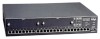
... terminal connection or via TEL- NET • SNMP Management support • BOOTP and TFTP support • Control over user access rights • Creation of virtual LANs • Stand-alone (per switch or stack) or distributed (switch network) VLAN • IGMP Pruning Introduction View of the switch is shown below: Slot A 1 2 3 4 5 6 7 8 Slot B 9 10 11 12 13 14 15 16 LEDs Off Solid Green 10 Mbps 100 Mbps Orange Half duplex Full duplex Port Status Intel Express 510T Switch LEDs Solid Blink Green Link Activity Orange Disable Collision Status...
... terminal connection or via TEL- NET • SNMP Management support • BOOTP and TFTP support • Control over user access rights • Creation of virtual LANs • Stand-alone (per switch or stack) or distributed (switch network) VLAN • IGMP Pruning Introduction View of the switch is shown below: Slot A 1 2 3 4 5 6 7 8 Slot B 9 10 11 12 13 14 15 16 LEDs Off Solid Green 10 Mbps 100 Mbps Orange Half duplex Full duplex Port Status Intel Express 510T Switch LEDs Solid Blink Green Link Activity Orange Disable Collision Status...

User Guide
Page 15
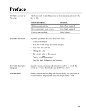
... fan outlet and the main supply cable, so you should position the switch with the rear panel facing away from you. Connects an external redundant power supply. C H A P T E R 1 Intel Express 510T Switch Introduction View of the switch. A socket to connect the power cord to all local and national regulations governing the installation and connection of electrical devices when installing the switch. 5 Installation You must adhere to the main supply. If the internal power supply fails...
... fan outlet and the main supply cable, so you should position the switch with the rear panel facing away from you. Connects an external redundant power supply. C H A P T E R 1 Intel Express 510T Switch Introduction View of the switch. A socket to connect the power cord to all local and national regulations governing the installation and connection of electrical devices when installing the switch. 5 Installation You must adhere to the main supply. If the internal power supply fails...

User Guide
Page 18
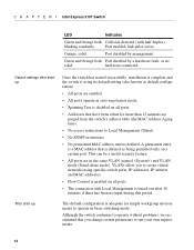
... 15 16 LEDs Off Solid Green 10 Mbps 100 Mbps Orange Half duplex Full duplex Port Status Intel Express 510T Switch LEDs Solid Blink Green Link Activity Orange Disable Collision Status Temperature RPS Power Reset 17 18 19 20 21 22 23 24 Console 9600-8-N-1 1590 Make sure that the temperature of the rack environment does not exceed the recommended operating temperature for the switch. 8 Make sure that you attach the mounting brackets to...
... 15 16 LEDs Off Solid Green 10 Mbps 100 Mbps Orange Half duplex Full duplex Port Status Intel Express 510T Switch LEDs Solid Blink Green Link Activity Orange Disable Collision Status Temperature RPS Power Reset 17 18 19 20 21 22 23 24 Console 9600-8-N-1 1590 Make sure that the temperature of the rack environment does not exceed the recommended operating temperature for the switch. 8 Make sure that you attach the mounting brackets to...

User Guide
Page 20
... instructions in question. Connecting Other Devices Introduction Use shielded cables Cables for exam- Workstation or server Straight-through cable 1:1 10 Only use a... Crossover cable ple another Intel switch or hub) Device with MDI ports Straight-through cable 1:1 Device with the plate and secure using the screws. Slide the module out completely. 5 Cover the empty module port with MDI-X ports (for the LAN Ports Incorrect cabling is explicitly specified in the installation manual of network configuration problems Shielded cables...
... instructions in question. Connecting Other Devices Introduction Use shielded cables Cables for exam- Workstation or server Straight-through cable 1:1 10 Only use a... Crossover cable ple another Intel switch or hub) Device with MDI ports Straight-through cable 1:1 Device with the plate and secure using the screws. Slide the module out completely. 5 Cover the empty module port with MDI-X ports (for the LAN Ports Incorrect cabling is explicitly specified in the installation manual of network configuration problems Shielded cables...
User Guide
Page 24
... a certain port. VLANs allow you change certain parameters to Local Management (Telnet). • No SNMP restrictions. • No permanent MAC address entries defined. Green and Orange both Collision detected (with Local Management is enabled on all ports. • The connection with half duplex). Default settings after startup Once the switch has started successfully, installation is complete and the switch is using specific switch ports, IP addresses, IP subnets and MAC addresses. • Flow Control is timed-out after 10 minutes...
... a certain port. VLANs allow you change certain parameters to Local Management (Telnet). • No SNMP restrictions. • No permanent MAC address entries defined. Green and Orange both Collision detected (with Local Management is enabled on all ports. • The connection with half duplex). Default settings after startup Once the switch has started successfully, installation is complete and the switch is using specific switch ports, IP addresses, IP subnets and MAC addresses. • Flow Control is timed-out after 10 minutes...

User Guide
Page 31
... a switch or stack is contacted, the following switch commands: • Install - enables a switch or stack that has an IP address already assigned to save the new configuration before exiting. This contains one command, Exit which provides port and VLAN details for users using mouse actions. The Device menu contains the following commands are available through Intel Device View The Intel Device View window Many commands are asked if you want to be managed or configured. enables...
... a switch or stack is contacted, the following switch commands: • Install - enables a switch or stack that has an IP address already assigned to save the new configuration before exiting. This contains one command, Exit which provides port and VLAN details for users using mouse actions. The Device menu contains the following commands are available through Intel Device View The Intel Device View window Many commands are asked if you want to be managed or configured. enables...

User Guide
Page 41
... for configuration and monitoring. Opens that port's Setup menu. 31 You can fully manage the switch or stack using this display. Using a mouse makes it easier to the state of the switch/stack. For example, the LEDs change color according to operate Intel Device View and saves you time: Mouse action Right-click switch Right-click stack border Right-click a port Double left-click switch Double left-click a port Information Shows the switch-related...
... for configuration and monitoring. Opens that port's Setup menu. 31 You can fully manage the switch or stack using this display. Using a mouse makes it easier to the state of the switch/stack. For example, the LEDs change color according to operate Intel Device View and saves you time: Mouse action Right-click switch Right-click stack border Right-click a port Double left-click switch Double left-click a port Information Shows the switch-related...

User Guide
Page 42
... to be lost. Also enables the switch's firmware to add new ones or change existing ones. Reboots the switch and provides information about the type of switch, its location, who is safe by saving it to the flash memory, by backing up to disk and by being able to the factory default configuration. Ensures the switch's configuration is responsible for it be upgraded. Gives detailed monitoring information for Spanning Tree statistics...
... to be lost. Also enables the switch's firmware to add new ones or change existing ones. Reboots the switch and provides information about the type of switch, its location, who is safe by saving it to the flash memory, by backing up to disk and by being able to the factory default configuration. Ensures the switch's configuration is responsible for it be upgraded. Gives detailed monitoring information for Spanning Tree statistics...

User Guide
Page 59
... stacks. For further configuration of a link, for the link. 8 Click OK. C H A P T E R 3 Standard Configuration Link Aggregation Purpose Combines two or four adjacent ports to the list • Delete an entry Adding an Aggregate Link To set up and add an aggregate link: 1 Select Device Setup or Stack Setup. 2 Click Link Aggregation. 3 Click Add. 4 For a stack, click Switch and select one from the list. 5 Click Aggregation width: and select 2 Ports or 4 Ports. 6 Click Anchor Port and select a port. 7 Type a unique name for example in a VLAN, use...
... stacks. For further configuration of a link, for the link. 8 Click OK. C H A P T E R 3 Standard Configuration Link Aggregation Purpose Combines two or four adjacent ports to the list • Delete an entry Adding an Aggregate Link To set up and add an aggregate link: 1 Select Device Setup or Stack Setup. 2 Click Link Aggregation. 3 Click Add. 4 For a stack, click Switch and select one from the list. 5 Click Aggregation width: and select 2 Ports or 4 Ports. 6 Click Anchor Port and select a port. 7 Type a unique name for example in a VLAN, use...

User Guide
Page 62
Switching To change the password: 1 Select Device Setup or Stack Setup. 2 Click TFTP. 3 Type the old password. 4 Type the new password. 5 Retype the new password (in the filter before being purged: 1 Select Device Setup or Stack Setup. 2 Click Switching. 3 Click MAC Address Ageing. 4 Type the required number of staff authorized to transfer TFTP files by changing the TFTP password. To change the time a MAC address is kept in Retype new). 6 Select OK. C H A P T E R 3 Standard Configuration Changing password details Changing the MAC address ageing time TFTP To give added security...
Switching To change the password: 1 Select Device Setup or Stack Setup. 2 Click TFTP. 3 Type the old password. 4 Type the new password. 5 Retype the new password (in the filter before being purged: 1 Select Device Setup or Stack Setup. 2 Click Switching. 3 Click MAC Address Ageing. 4 Type the required number of staff authorized to transfer TFTP files by changing the TFTP password. To change the time a MAC address is kept in Retype new). 6 Select OK. C H A P T E R 3 Standard Configuration Changing password details Changing the MAC address ageing time TFTP To give added security...

User Guide
Page 65
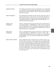
... the VLAN setup (because VLAN B needs these default values may arise when using VLANs Why change the: • Priority given to receive messages). VLAN A B Slot A 1 2 3 4 5 6 7 8 Slot B 9 10 11 12 13 14 15 16 LEDs Off Solid Green 10 Mbps 100 Mbps Orange Half duplex Full duplex Port Status Intel Express 510T Switch LEDs Solid Blink Green Link Activity Orange Disable Collision Status Temperature RPS Power Reset 17 18 19 20 21 22 23 24 Console 9600-8-N-1 STP Switch 1 Slot A 1 2 3 4 5 6 7 8 Slot B 9 10 11 12...
... the VLAN setup (because VLAN B needs these default values may arise when using VLANs Why change the: • Priority given to receive messages). VLAN A B Slot A 1 2 3 4 5 6 7 8 Slot B 9 10 11 12 13 14 15 16 LEDs Off Solid Green 10 Mbps 100 Mbps Orange Half duplex Full duplex Port Status Intel Express 510T Switch LEDs Solid Blink Green Link Activity Orange Disable Collision Status Temperature RPS Power Reset 17 18 19 20 21 22 23 24 Console 9600-8-N-1 STP Switch 1 Slot A 1 2 3 4 5 6 7 8 Slot B 9 10 11 12...

User Guide
Page 116
... switch configuration. During normal operation (the switch is running and the Status LED is provided. The switch software may be restored/downloaded from such a situation when the Recovery Manager of Intel Device View cannot be applied, the maintenance mode is green) the Console port will give access to a menu, identical to the one accessible via a telnet connection to the switch. In the following is provided on the network. The software for restoring or upgrading the switch software. C H A P T E R 7 Console Port Use and Troubleshooting Use...
... switch configuration. During normal operation (the switch is running and the Status LED is provided. The switch software may be restored/downloaded from such a situation when the Recovery Manager of Intel Device View cannot be applied, the maintenance mode is green) the Console port will give access to a menu, identical to the one accessible via a telnet connection to the switch. In the following is provided on the network. The software for restoring or upgrading the switch software. C H A P T E R 7 Console Port Use and Troubleshooting Use...
User Guide
Page 117
... files are named after reset (System LED goes red), it impossible to contact the switch by mistake has made it may also be backed up the Configuration Restoring the Configuration Reset to Factory Defaults If a working switch software needs to be upgraded, it is recommended to do this will discard the existing configuration in Intel Device View rather than manual TFTP. The two configuration files may be used to use Intel Device View for doing backup...
... files are named after reset (System LED goes red), it impossible to contact the switch by mistake has made it may also be backed up the Configuration Restoring the Configuration Reset to Factory Defaults If a working switch software needs to be upgraded, it is recommended to do this will discard the existing configuration in Intel Device View rather than manual TFTP. The two configuration files may be used to use Intel Device View for doing backup...

User Guide
Page 124
... a cable is a normal occurrence for that port or address. During this learning state, the switch will not forward data traffic. To manage the switch from a PC with the switch. Action: Avoid loops, or alternatively, either enable STP on , but one or more of the port STATUS LEDs are both on all the ports (using Device Setup) or specific ports (using Port Setup). To troubleshoot communications problems If the POWER LED and the STATUS LED are off, then: 1 Reset the switch using IEEE...
... a cable is a normal occurrence for that port or address. During this learning state, the switch will not forward data traffic. To manage the switch from a PC with the switch. Action: Avoid loops, or alternatively, either enable STP on , but one or more of the port STATUS LEDs are both on all the ports (using Device Setup) or specific ports (using Port Setup). To troubleshoot communications problems If the POWER LED and the STATUS LED are off, then: 1 Reset the switch using IEEE...

User Guide
Page 135
... to authentication list, 46 new switches, 26 Airflow, 7 Alarms, RMON, 77 Altitude, 101 Approvals CE Mark, 100 emission, 100 safety, 100 susceptibility, 100 Authentication add a device, 46 purpose, 45 Auto-negotiation disable, 59 Avoiding damage to the circuit board, 9 B Bootload using maintenance mode, 108 Button functions, 4 C Cable for the Console Port, 11 for the LAN Ports, 10 shielded, 10 wiring color code, 12 Change default forwarding mode, 53 duplex mode, 60 error limits for adaptive forwarding, 54 flow control, 53...
... to authentication list, 46 new switches, 26 Airflow, 7 Alarms, RMON, 77 Altitude, 101 Approvals CE Mark, 100 emission, 100 safety, 100 susceptibility, 100 Authentication add a device, 46 purpose, 45 Auto-negotiation disable, 59 Avoiding damage to the circuit board, 9 B Bootload using maintenance mode, 108 Button functions, 4 C Cable for the Console Port, 11 for the LAN Ports, 10 shielded, 10 wiring color code, 12 Change default forwarding mode, 53 duplex mode, 60 error limits for adaptive forwarding, 54 flow control, 53...

User Guide
Page 136
..., 62 STP state of a port, 61 TFTP password, 52 time to measure errors, 54 timeout details, 51 Clearance, 100 Clock set, 45 Color Code for Main window, 35 Matrix Ports, 23 Commands in Maintenance Mode, 110 Communication problems, how to solve, 114 Concept Intel Device View, 20 Configuration changes lost, 113 standard level, 41 Connect main power, 5, 12 Management PC, 11 other devices, 10 redundant power supply, 5 Connections number of, 101 CONSOLE port function, 4 Consumption of power, 102 Contacting Customer Support, 115...
..., 62 STP state of a port, 61 TFTP password, 52 time to measure errors, 54 timeout details, 51 Clearance, 100 Clock set, 45 Color Code for Main window, 35 Matrix Ports, 23 Commands in Maintenance Mode, 110 Communication problems, how to solve, 114 Concept Intel Device View, 20 Configuration changes lost, 113 standard level, 41 Connect main power, 5, 12 Management PC, 11 other devices, 10 redundant power supply, 5 Connections number of, 101 CONSOLE port function, 4 Consumption of power, 102 Contacting Customer Support, 115...
User Guide
Page 137
I N D E X Intel® Express 510T Switch transfer using TFTP, 116 Flow control change on a port, 61 change on switch, 53 default, 14 Forward delay expiry time change, 57 Forwarding mode on a port change, 60 Frequency, 102 Front panel LED, 4 ports, 4 view, 3 G Getting started, vii H Hardware details, 73 features, 2 Hello expiry time change, 56 Help description, vii History, RMON, 76 Humidity, 101 I Identify the switch, 43, 72 IGMP pruning, 69 enable, 70 Improve switch security, 42 Information about changes to VLANs, 86 about the domain...
I N D E X Intel® Express 510T Switch transfer using TFTP, 116 Flow control change on a port, 61 change on switch, 53 default, 14 Forward delay expiry time change, 57 Forwarding mode on a port change, 60 Frequency, 102 Front panel LED, 4 ports, 4 view, 3 G Getting started, vii H Hardware details, 73 features, 2 Hello expiry time change, 56 Help description, vii History, RMON, 76 Humidity, 101 I Identify the switch, 43, 72 IGMP pruning, 69 enable, 70 Improve switch security, 42 Information about changes to VLANs, 86 about the domain...

User Guide
Page 138
... a port, 58 M MAC addresses ageing time, 14 change ageing time, 52 number per port, 102 permanent entries, 14 Main power connection, 102 Main window color coding, 35 commands for a port, 35 commands for a single switch, 32 commands for a switch in a stack, 34 commands on a stack border, 33 mouse moves, 31 Maintenance Mode, 4, 108 commands, 110 Management using Intel Device View, 72 Management PC, 11 Manager, 94 Managing the switch, 27 Memory sizes, 103 Message age expiry time change, 56 Missing parts, 6 Module removal, 10 Monitor distribution of frames on a port, 88...
... a port, 58 M MAC addresses ageing time, 14 change ageing time, 52 number per port, 102 permanent entries, 14 Main power connection, 102 Main window color coding, 35 commands for a port, 35 commands for a single switch, 32 commands for a switch in a stack, 34 commands on a stack border, 33 mouse moves, 31 Maintenance Mode, 4, 108 commands, 110 Management using Intel Device View, 72 Management PC, 11 Manager, 94 Managing the switch, 27 Memory sizes, 103 Message age expiry time change, 56 Missing parts, 6 Module removal, 10 Monitor distribution of frames on a port, 88...

User Guide
Page 139
... wiring color code, 12 Power supply, 102 to a rack, 12 Power-up port LED states, 13 procedure, 13 Prerequisite knowledge, viii Products covered, viii Protocols supported, 103 Purpose, 2, 65 Q Quick Start description, vii R Rack power supply, 12 Read before starting, 6 Rear panel connections, 5 description, 5 Received packets monitor the total activity, 74, 81 Recovery Manager, 94 Redundant power supply connector, 5 purpose, 5 Redundant power supply. I N D E X Intel® Express 510T Switch CONSOLE, 4 DB-9, 4 disable, 59 disabled by default, 14 Software features, 3 Spanning Tree, 14 129...
... wiring color code, 12 Power supply, 102 to a rack, 12 Power-up port LED states, 13 procedure, 13 Prerequisite knowledge, viii Products covered, viii Protocols supported, 103 Purpose, 2, 65 Q Quick Start description, vii R Rack power supply, 12 Read before starting, 6 Rear panel connections, 5 description, 5 Received packets monitor the total activity, 74, 81 Recovery Manager, 94 Redundant power supply connector, 5 purpose, 5 Redundant power supply. I N D E X Intel® Express 510T Switch CONSOLE, 4 DB-9, 4 disable, 59 disabled by default, 14 Software features, 3 Spanning Tree, 14 129...
