
English Manual
Page 1
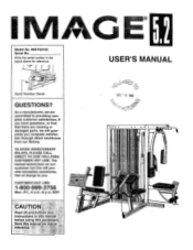
... Mon.-Fri., 6 a.m.-6 p.m. IMSY52162 Serial No. MST CAUTI Read all precautions and instructions in the space above for future reference 5. The trained technicians on our customer hot line will guarantee you have questions, or find that there are committed to you. TO AVOID UNNECESSARY DELAYS, PLEASE CALL DIRECT TO OUR TOLL-FREE CUSTOMER HOT LINE. USER'S MANUAL E C 1 6 1996 C11N...
... Mon.-Fri., 6 a.m.-6 p.m. IMSY52162 Serial No. MST CAUTI Read all precautions and instructions in the space above for future reference 5. The trained technicians on our customer hot line will guarantee you have questions, or find that there are committed to you. TO AVOID UNNECESSARY DELAYS, PLEASE CALL DIRECT TO OUR TOLL-FREE CUSTOMER HOT LINE. USER'S MANUAL E C 1 6 1996 C11N...

English Manual
Page 2
... PRECAUTIONS BEFORE YOU BEGIN ASSEMBLY HOW TO ADJUST THE IMAGE 5.2 TROUBLE-SHOOTING AND MAINTENANCE CABLE DIAGRAMS ORDERING REPLACEMENT PARTS LIMITED WARRANTY 2 3 4 27 29 30 Back Cover Back Cover - Remove the PART IDENTIFICATION CHART and the PART LIST/EXPLODED DRAWING before using thu low pulley station. 13. Use the IMAGE 5.2 only on the pulleys at all parts often. Keep small children and pets away from moving parts. IMAGE 5.2. 2. When assembling the top frame and front and rear uprights, do not put...
... PRECAUTIONS BEFORE YOU BEGIN ASSEMBLY HOW TO ADJUST THE IMAGE 5.2 TROUBLE-SHOOTING AND MAINTENANCE CABLE DIAGRAMS ORDERING REPLACEMENT PARTS LIMITED WARRANTY 2 3 4 27 29 30 Back Cover Back Cover - Remove the PART IDENTIFICATION CHART and the PART LIST/EXPLODED DRAWING before using thu low pulley station. 13. Use the IMAGE 5.2 only on the pulleys at all parts often. Keep small children and pets away from moving parts. IMAGE 5.2. 2. When assembling the top frame and front and rear uprights, do not put...

English Manual
Page 3
... of the body. ASSEMBLED DIMENSIONS: Height: 80" Base: 94" x 72" Arm Pads Backrest Press Arm Chest Pad Weight Shields Ab Pulley 0 0 0 0 Lat Bar Lat Bar Holder Butterfly Arms Ab Strap Backrest Leg Press 0 Leg Lever Lock Knob 0 Seat Curl Lever Weight Stacks Curl Bar Seats 3 Low Pulley Station To help you to develop every major muscle group of weight stations designed to achieve the specific results you , please note the product model number and serial number before using the IMAGE® 5.2 Home Gym System.
... of the body. ASSEMBLED DIMENSIONS: Height: 80" Base: 94" x 72" Arm Pads Backrest Press Arm Chest Pad Weight Shields Ab Pulley 0 0 0 0 Lat Bar Lat Bar Holder Butterfly Arms Ab Strap Backrest Leg Press 0 Leg Lever Lock Knob 0 Seat Curl Lever Weight Stacks Curl Bar Seats 3 Low Pulley Station To help you to develop every major muscle group of weight stations designed to achieve the specific results you , please note the product model number and serial number before using the IMAGE® 5.2 Home Gym System.

English Manual
Page 4
... as shown. Locate and open -end or closed-end wrenches, or a set of open the parts bag labeled "IMAGE 5.2 Steps 1-7." Be sure that the Front Upright is turned so that the adjustment tube is completed. • For help identifying the small parts used . • Place all parts in a cleared area and remove the packing materials; Locate and npPn thP paric hag lahPIPci "IMAGE 5.2 Shield Assembly." The Brackets...
... as shown. Locate and open -end or closed-end wrenches, or a set of open the parts bag labeled "IMAGE 5.2 Steps 1-7." Be sure that the Front Upright is turned so that the adjustment tube is completed. • For help identifying the small parts used . • Place all parts in a cleared area and remove the packing materials; Locate and npPn thP paric hag lahPIPci "IMAGE 5.2 Shield Assembly." The Brackets...

English Manual
Page 7
.... Move the Seat Bracket so that each of the Press Frame Handle (82) to the Rear Hpright (77) with four 1/4" x 3/4" Screws (24). Attach the other end of the thirty-eight Weights (75). Note: The post on the Seat Bracket is on the Curl Frame (109). Turn the Lock Knob clockwise until the Lock Knob locks into the tube on the bottom. )1( 9. Attach a Seat...
.... Move the Seat Bracket so that each of the Press Frame Handle (82) to the Rear Hpright (77) with four 1/4" x 3/4" Screws (24). Attach the other end of the thirty-eight Weights (75). Note: The post on the Seat Bracket is on the Curl Frame (109). Turn the Lock Knob clockwise until the Lock Knob locks into the tube on the bottom. )1( 9. Attach a Seat...

English Manual
Page 9
... (3), used in this assembly step, be pointed away from the Washer, as shown in the Top Frame (76). Press two 3/4" Retainers (3) onto the axle, one at a time. a 53 Lubricate Axle 60 4 76 53 Lubricate Axle 58 9 3 58 -4 16. The teeth on the Left Butterfly Arm. If they must be sure that the Weld Cover is turned so the open side...
... (3), used in this assembly step, be pointed away from the Washer, as shown in the Top Frame (76). Press two 3/4" Retainers (3) onto the axle, one at a time. a 53 Lubricate Axle 60 4 76 53 Lubricate Axle 58 9 3 58 -4 16. The teeth on the Left Butterfly Arm. If they must be sure that the Weld Cover is turned so the open side...

English Manual
Page 10
...the Dome Cap, as shown in the Press Frame (87). Lubricate the 1/2" x 8 7/8" Axle (48). Locate and open side facing up . Tap the 1/2" x 8 7/8" Axle (48) into the Leg Press Arm (88). Tool 7 • 86 • 2 7-4) 87 2 8 Lubricate-48 Retainer 7 Tool 10 If they ...removed, you thoroughly understand the assembly step. Tap the 1/2" x 4 5/8" Axle (50) into the Dome Cap. Align the hole in the lower end of the Moment Arm with the holes in the Dome Cap. Set a 1/2" Dome Cap (7) on the floor with the open the parts bag labeled "IMAGE 5.2 Steps 17-27." Using...
...the Dome Cap, as shown in the Press Frame (87). Lubricate the 1/2" x 8 7/8" Axle (48). Locate and open side facing up . Tap the 1/2" x 8 7/8" Axle (48) into the Leg Press Arm (88). Tool 7 • 86 • 2 7-4) 87 2 8 Lubricate-48 Retainer 7 Tool 10 If they ...removed, you thoroughly understand the assembly step. Tap the 1/2" x 4 5/8" Axle (50) into the Dome Cap. Align the hole in the lower end of the Moment Arm with the holes in the Dome Cap. Set a 1/2" Dome Cap (7) on the floor with the open the parts bag labeled "IMAGE 5.2 Steps 17-27." Using...

English Manual
Page 11
... you route the cables correctly. 0 21. 19. Attach the Right Arm (84) to the Moment Arm (86) with two 3/8" x 2 1/2" Bolts (13) and two 3/8" Nylon Locknuts (1). 19 13-Lubricate Attach the Left Arm (83) to make sure that the Bushing is the shortest Cable. Refer to 0 the CABLE DIAGRAMS on pages 30 and 31 during assembly to the Moment Arm (86) in line with the cable guide...
... you route the cables correctly. 0 21. 19. Attach the Right Arm (84) to the Moment Arm (86) with two 3/8" x 2 1/2" Bolts (13) and two 3/8" Nylon Locknuts (1). 19 13-Lubricate Attach the Left Arm (83) to make sure that the Bushing is the shortest Cable. Refer to 0 the CABLE DIAGRAMS on pages 30 and 31 during assembly to the Moment Arm (86) in line with the cable guide...

English Manual
Page 15
...) inside the Top Frame holds the Cable in the groove of the Pulley. 32. Attach a 3 1/2" Pulley (30) to the Front Upright with a 3/8" x 3" Bolt (11), two 3/8" Washers (5), and a 3/8" Nylon Locknut (1). Feed the Ab Cable (107) up through the hole in the Front Upright (65) with a 3/8" x 3" Bolt (11), two 3/8" Washers (5), and a 3/8" Nylon Locknut (1). The Cable and the Pulley should be on the indi...
...) inside the Top Frame holds the Cable in the groove of the Pulley. 32. Attach a 3 1/2" Pulley (30) to the Front Upright with a 3/8" x 3" Bolt (11), two 3/8" Washers (5), and a 3/8" Nylon Locknut (1). Feed the Ab Cable (107) up through the hole in the Front Upright (65) with a 3/8" x 3" Bolt (11), two 3/8" Washers (5), and a 3/8" Nylon Locknut (1). The Cable and the Pulley should be on the indi...

English Manual
Page 16
... Top Frame in this step was 36 pre-attached for shipping purposes. A 1 f6° 19 91 36. Note: The Pulley (30) used in the indicated location. 0 - .-j'caa 43 35 , w Et Remove the 3/8" x 2" Bolt (19) and the 3/8" Nylon Locknut (1) attaching the 3 1/2" Pulley (30) to the Ab Cable (107) 34 with only one set of the "U"-Bracket (91) with a 3/8" x 3/4" Bolt (57) and a 3/8" Nylon Jam...
... Top Frame in this step was 36 pre-attached for shipping purposes. A 1 f6° 19 91 36. Note: The Pulley (30) used in the indicated location. 0 - .-j'caa 43 35 , w Et Remove the 3/8" x 2" Bolt (19) and the 3/8" Nylon Locknut (1) attaching the 3 1/2" Pulley (30) to the Ab Cable (107) 34 with only one set of the "U"-Bracket (91) with a 3/8" x 3/4" Bolt (57) and a 3/8" Nylon Jam...

English Manual
Page 17
... pad tube on the Seat Frame (98). Attach the Locking Pin (55) to the Front Upright (65) with a 3/8" Nut (21). Do not completely tighten the Nut. The Locking Pin must be able to rotate. 38. Thread the 3/8" Knob (54) onto the Locking Pin (55). Attach the Seat Frame (98) to the Leg Lever (99) with two 3/8" x 5" Bolts (14), a Support Bracket (78), and two...
... pad tube on the Seat Frame (98). Attach the Locking Pin (55) to the Front Upright (65) with a 3/8" Nut (21). Do not completely tighten the Nut. The Locking Pin must be able to rotate. 38. Thread the 3/8" Knob (54) onto the Locking Pin (55). Attach the Seat Frame (98) to the Leg Lever (99) with two 3/8" x 5" Bolts (14), a Support Bracket (78), and two...

English Manual
Page 19
Wrap the Curl Cable (106) around the Pulley from the direction shown. 19 91 81 30 106 46. Re-attach the Pulley and the "L"-Bracket to the lowest set of holes in this step was 45 pre-attached for shipping purposes. Attach a 3/8" x 2 3/4" Bolt (17) to the indicated "U"-Bracket (91). Remove the 3/8" x 2" Bolt (19) and the 3/8" Nylon Locknut (1) attaching the lower 3 1/2" Pulley (30) and the "L"-Bracket (81...
Wrap the Curl Cable (106) around the Pulley from the direction shown. 19 91 81 30 106 46. Re-attach the Pulley and the "L"-Bracket to the lowest set of holes in this step was 45 pre-attached for shipping purposes. Attach a 3/8" x 2 3/4" Bolt (17) to the indicated "U"-Bracket (91). Remove the 3/8" x 2" Bolt (19) and the 3/8" Nylon Locknut (1) attaching the lower 3 1/2" Pulley (30) and the "L"-Bracket (81...

English Manual
Page 20
... the Front Upright (65) with the Bolt and the Nylon Locknut. The Pulley Cover must be oriented as shown and be routed around the Pulley. Attach the Pulley to hold the Cable in this step was 47 pre-attached for shipping purposes. Attach the Pulley and a Pulley Cover (23) to the indicated "U"-Bracket (91). Locate and open the parts bag labeled "IMAGE 5.2 Steps 49-67." Note: The Pulley (30) used in the...
... the Front Upright (65) with the Bolt and the Nylon Locknut. The Pulley Cover must be oriented as shown and be routed around the Pulley. Attach the Pulley to hold the Cable in this step was 47 pre-attached for shipping purposes. Attach the Pulley and a Pulley Cover (23) to the indicated "U"-Bracket (91). Locate and open the parts bag labeled "IMAGE 5.2 Steps 49-67." Note: The Pulley (30) used in the...

English Manual
Page 23
See the inset drawing. Be sure that the Cable is routed under the Pulley as shown. Note: The Pulleys (30) used in step 58. Re-attach the Pulley to indicated side of the Pulley. Remove the 3/8" x 1 3/4" Bolt (10) from the Leg Press Arm (88). Wrap the Press Cable (95) around one of upright 30 1 23 ,. ---16 -----.5 95 87 95 l @/ 30 8 a o 30 20 izi 59 III tr--1U s \, 1 1 6* 30...
See the inset drawing. Be sure that the Cable is routed under the Pulley as shown. Note: The Pulleys (30) used in step 58. Re-attach the Pulley to indicated side of the Pulley. Remove the 3/8" x 1 3/4" Bolt (10) from the Leg Press Arm (88). Wrap the Press Cable (95) around one of upright 30 1 23 ,. ---16 -----.5 95 87 95 l @/ 30 8 a o 30 20 izi 59 III tr--1U s \, 1 1 6* 30...

English Manual
Page 26
... this manual to the Lower Shield Bracket (119) with two of each cable a few times to make sure that the cables move smoothly. Attach that there is used. 2R Make sure that all parts are properly routed. Note: The Selftapping Screws will be explained in the Brackets with two 1/2" Self-tapping Screws (118). Align the holes in HOW TO ADJUST THE IMAGES 5.2, beginning...
... this manual to the Lower Shield Bracket (119) with two of each cable a few times to make sure that the cables move smoothly. Attach that there is used. 2R Make sure that all parts are properly routed. Note: The Selftapping Screws will be explained in the Brackets with two 1/2" Self-tapping Screws (118). Align the holes in HOW TO ADJUST THE IMAGES 5.2, beginning...

English Manual
Page 27
... starting position for each exercise. The Nylon Strap (103) can be adjusted. Be sure to the cables and pulleys, the amount of resistance at each weight station. IMPORTANT: When attaching the lat bar or nylon strap, make sure that the attachments are in the cables or chain as an exercise is touching the Weights, and turn the bent end downward. For some exercises, the Chain (101) should be set...
... starting position for each exercise. The Nylon Strap (103) can be adjusted. Be sure to the cables and pulleys, the amount of resistance at each weight station. IMPORTANT: When attaching the lat bar or nylon strap, make sure that the attachments are in the cables or chain as an exercise is touching the Weights, and turn the bent end downward. For some exercises, the Chain (101) should be set...

English Manual
Page 29
... the Top Weight Cover. If the cables need to a different set of holes in the proper position and that the Cable and Pulley move one of the 3 1/2" Pulleys (30), remove the 3/8" Nylon Locknut (1) and the 3/8" x 2" Bolt (19) from the "U"-Bracket (91). TROUBLE-SHOOTING AND MAINTENANCE Inspect and tighten all parts each time you use solvents. Replace any worn parts immediately. Do not use the home gym system. Re-attach the Pulley and the...
... the Top Weight Cover. If the cables need to a different set of holes in the proper position and that the Cable and Pulley move one of the 3 1/2" Pulleys (30), remove the 3/8" Nylon Locknut (1) and the 3/8" x 2" Bolt (19) from the "U"-Bracket (91). TROUBLE-SHOOTING AND MAINTENANCE Inspect and tighten all parts each time you use solvents. Replace any worn parts immediately. Do not use the home gym system. Re-attach the Pulley and the...

English Manual
Page 30
... the proper route for each Cable have been labeled. The starting and ending points of the Butterfly Cable (96), the Curl Cable (106), the Lat Cable (97), the Press Cable (95), and the Ab Cable (107). Butterfly Cable (96) Curl Cable (106) 1-Right Butterfly Arm 3 0 0 3 0 0 4 2 5-Left Butterfly Arm 4-N 5 3 O 0' o' 0 2 4 0 0 0 7 8-Preacher Curl 6 Low Pulley-1 8 30 Use the diagrams to be sure that the Cables have not been correctly routed, the IMAGE 5.2 will...
... the proper route for each Cable have been labeled. The starting and ending points of the Butterfly Cable (96), the Curl Cable (106), the Lat Cable (97), the Press Cable (95), and the Ab Cable (107). Butterfly Cable (96) Curl Cable (106) 1-Right Butterfly Arm 3 0 0 3 0 0 4 2 5-Left Butterfly Arm 4-N 5 3 O 0' o' 0 2 4 0 0 0 7 8-Preacher Curl 6 Low Pulley-1 8 30 Use the diagrams to be sure that the Cables have not been correctly routed, the IMAGE 5.2 will...

English Manual
Page 32
..., loss of enjoyment or use, costs of removal, installation or other consequential damages of purchase. LIMITED WARRANTY ICON Health & Fitness, Inc. (ICON), warrants this prnriiirt to be prepared to give the following information: • The MODEL NUMBER of the product (IMSY52162). • The NAME of the product (IMAGE® 5.2 Home Gym System). • The SERIAL NUMBER of the product (see the PART LIST/EXPLODED DRAWING attached to the center of...
..., loss of enjoyment or use, costs of removal, installation or other consequential damages of purchase. LIMITED WARRANTY ICON Health & Fitness, Inc. (ICON), warrants this prnriiirt to be prepared to give the following information: • The MODEL NUMBER of the product (IMSY52162). • The NAME of the product (IMAGE® 5.2 Home Gym System). • The SERIAL NUMBER of the product (see the PART LIST/EXPLODED DRAWING attached to the center of...

English Manual
Page 39
... Arm Right Butterfly Arm Butterfly Arm Pad Backrest Seat Backrest Plate Front Upright Left Support Plate Right Support Plate Weight Guide Weight Tube Bumper Weight Tube Top Weight Top Weight Cover 3/8" x 1 1/2" Allen Bolt 1/2" Nut Weight Top Frame Rear Upright Support Bracket Press Seat Bracket "I"-Plate "L"-Bracket Press Frame Handle Left Arm Right Arm Handle Moment Arm Press Frame Leg Press Arm Press Plate Square Bumper "U"-Bracket Lat Bar Row Bar Base Press Cable Butterfly Cable Lat Cable Seat Frame Leg Lever Weight Pin 101 1 • Chain 102 2 Cable Clip 103 1 Nylon Strap 104 76 Weight...
... Arm Right Butterfly Arm Butterfly Arm Pad Backrest Seat Backrest Plate Front Upright Left Support Plate Right Support Plate Weight Guide Weight Tube Bumper Weight Tube Top Weight Top Weight Cover 3/8" x 1 1/2" Allen Bolt 1/2" Nut Weight Top Frame Rear Upright Support Bracket Press Seat Bracket "I"-Plate "L"-Bracket Press Frame Handle Left Arm Right Arm Handle Moment Arm Press Frame Leg Press Arm Press Plate Square Bumper "U"-Bracket Lat Bar Row Bar Base Press Cable Butterfly Cable Lat Cable Seat Frame Leg Lever Weight Pin 101 1 • Chain 102 2 Cable Clip 103 1 Nylon Strap 104 76 Weight...


