
User Manual
Page 1
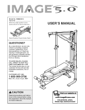
... missing or damaged parts, we are committed to providing complete customer satisfaction. As a manufacturer, we will provide immediate assistance, free of charge. The trained technicians on our customer hot line will guarantee complete satisfaction through direct assistance from our factory. Write the serial number in this manual before using this manual for future reference. Serial Number Decal (Under Seat) QUESTIONS? TO AVOID...
... missing or damaged parts, we are committed to providing complete customer satisfaction. As a manufacturer, we will provide immediate assistance, free of charge. The trained technicians on our customer hot line will guarantee complete satisfaction through direct assistance from our factory. Write the serial number in this manual before using this manual for future reference. Serial Number Decal (Under Seat) QUESTIONS? TO AVOID...
User Manual
Page 2
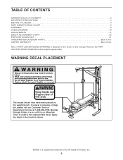
... BEGIN 4 PART IDENTIFICATION CHART 5 ASSEMBLY 6 CABLE DIAGRAM 16 ADJUSTMENTS 17 BENCH ADJUSTMENT CHART 20 EXERCISE GUIDELINES 21 ORDERING REPLACEMENT PARTS Back Cover LIMITED WARRANTY Back Cover Note: A PART LIST/EXPLODED DRAWING is missing or illegible, please call our Customer Service Department toll-free at 1-800-999-3756, Monday through Friday, 6 a.m. IMAGE is a registered trademark of this manual. Remove the PART LIST/EXPLODED DRAWING before beginning assembly. WARNING DECAL PLACEMENT Keep hands and fingers clear of ICON Health & Fitness, Inc...
... BEGIN 4 PART IDENTIFICATION CHART 5 ASSEMBLY 6 CABLE DIAGRAM 16 ADJUSTMENTS 17 BENCH ADJUSTMENT CHART 20 EXERCISE GUIDELINES 21 ORDERING REPLACEMENT PARTS Back Cover LIMITED WARRANTY Back Cover Note: A PART LIST/EXPLODED DRAWING is missing or illegible, please call our Customer Service Department toll-free at 1-800-999-3756, Monday through Friday, 6 a.m. IMAGE is a registered trademark of this manual. Remove the PART LIST/EXPLODED DRAWING before beginning assembly. WARNING DECAL PLACEMENT Keep hands and fingers clear of ICON Health & Fitness, Inc...
User Manual
Page 3
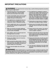
... the weight Cover the floor beneath the weight bench to support a maximum user weight of 250 pounds. Read all times. Do not use the weight bench. The weight bench does not include a barbell or weights. 12. Always place an equal amount of weight on the pulleys at any exercise program, consult your physician. Always set both weight rests at all parts are adequately informed of all instructions before using the leg lever. The weight bench is...
... the weight Cover the floor beneath the weight bench to support a maximum user weight of 250 pounds. Read all times. Do not use the weight bench. The weight bench does not include a barbell or weights. 12. Always place an equal amount of weight on the pulleys at any exercise program, consult your physician. Always set both weight rests at all parts are adequately informed of all instructions before using the leg lever. The weight bench is...
User Manual
Page 4
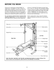
... product model number and serial number before using the weight bench. For your goal is IMBE29910. If you for selecting the versatile IMAGE® 5.0 weight bench. To help you want. The IMAGE® 5.0 offers a selection of weight stations designed to achieve the specific results you to develop every major muscle group of this manual carefully before calling. Whether your benefit, read this manual). Pulley Arm Pull-up Bar...
... product model number and serial number before using the weight bench. For your goal is IMBE29910. If you for selecting the versatile IMAGE® 5.0 weight bench. To help you want. The IMAGE® 5.0 offers a selection of weight stations designed to achieve the specific results you to develop every major muscle group of this manual carefully before calling. Whether your benefit, read this manual). Pulley Arm Pull-up Bar...

User Manual
Page 5
Note: Some small parts may have been pre-attached. If a part is the key number of the part, from the PART LIST in the center of this manual. M10 Washer (79) M10 Nylon Locknut (77) M6 Locknut (80) M6 Washer (62) M8 x 12mm Screw (43) M5 Washer (92) M10 x 45mm Bolt (76) M10 x 25mm Button Bolt (81) M4 x 19mm Screw (68) M6 x 16mm Bolt (72) 5 M10...
Note: Some small parts may have been pre-attached. If a part is the key number of the part, from the PART LIST in the center of this manual. M10 Washer (79) M10 Nylon Locknut (77) M6 Locknut (80) M6 Washer (62) M8 x 12mm Screw (43) M5 Washer (92) M10 x 45mm Bolt (76) M10 x 25mm Button Bolt (81) M4 x 19mm Screw (68) M6 x 16mm Bolt (72) 5 M10...
User Manual
Page 6
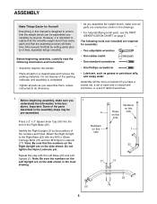
... until assembly is completed. • Tighten all parts as you assemble the weight bench, make sure you have a socket set, a set of open-end or closed-end wrenches, or a set of the parts described in the assembly steps may be assembled successfully by anyone. Repeat this step with two M10 x 62mm Carriage Bolts (74) and two M10 Nylon Locknuts (77). Do not dispose of the numbers and...
... until assembly is completed. • Tighten all parts as you assemble the weight bench, make sure you have a socket set, a set of open-end or closed-end wrenches, or a set of the parts described in the assembly steps may be assembled successfully by anyone. Repeat this step with two M10 x 62mm Carriage Bolts (74) and two M10 Nylon Locknuts (77). Do not dispose of the numbers and...

User Manual
Page 9
...the top of the Sliding Seat Frame. Slide the Sliding Seat Frame onto the Bench Frame (14) and engage the Knob into an adjustment hole in the same manner. Press a 60mm Square Inner Cap (46) into the ends of the Front Leg (18). Do not tighten the Nylon Locknuts yet. 12...steps 1-10. 11. Orient the Bench Frame (14) as it will go. Attach the Bench Frame to the Stabilizer with the bend on top. Press a 60mm Square Angled Inner Cap (95) into the indicated part of the Bench Frame (14). 13 14 9 95 64 Knob 26 15 26 Attach the Pull-up Bar (8) with two M10 x 62mm Carriage Bolts...
...the top of the Sliding Seat Frame. Slide the Sliding Seat Frame onto the Bench Frame (14) and engage the Knob into an adjustment hole in the same manner. Press a 60mm Square Inner Cap (46) into the ends of the Front Leg (18). Do not tighten the Nylon Locknuts yet. 12...steps 1-10. 11. Orient the Bench Frame (14) as it will go. Attach the Bench Frame to the Stabilizer with the bend on top. Press a 60mm Square Angled Inner Cap (95) into the indicated part of the Bench Frame (14). 13 14 9 95 64 Knob 26 15 26 Attach the Pull-up Bar (8) with two M10 x 62mm Carriage Bolts...
User Manual
Page 10
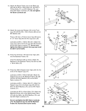
...Attach the Bench Frame (14) to the Back Leg (39) with the M4 x 19mm Screw (68) and an M5 Washer (92). Attach the Leg Lever (19) to the Front Leg (18) with the Bolt, two M10 Washers (79), and an M10 Nylon Locknut (77). Lubricate an M10 x 154mm Bolt (69). Lubricate two M10 x 45mm Bolts (76). Attach the Leg ...the ends of the Support Leg (13). Attach the 38 Backrest to the Backrest Frame (16) with the Bolts, two M10 Washers (79), and two M10 Nylon Locknuts (77). the Support Leg (13) and the Backrest Frame (16) must be able to the Sliding Seat Frame (15) with the Bolt, two M10 Washers...
...Attach the Bench Frame (14) to the Back Leg (39) with the M4 x 19mm Screw (68) and an M5 Washer (92). Attach the Leg Lever (19) to the Front Leg (18) with the Bolt, two M10 Washers (79), and an M10 Nylon Locknut (77). Lubricate an M10 x 154mm Bolt (69). Lubricate two M10 x 45mm Bolts (76). Attach the Leg ...the ends of the Support Leg (13). Attach the 38 Backrest to the Backrest Frame (16) with the Bolts, two M10 Washers (79), and two M10 Nylon Locknuts (77). the Support Leg (13) and the Backrest Frame (16) must be able to the Sliding Seat Frame (15) with the Bolt, two M10 Washers...
User Manual
Page 11
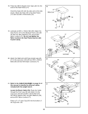
...77). Refer to the Leg Lever (19) with the Bolt, two M10 Washers (79), and an M10 Nylon Locknut (77). Route the Cable through the Front Leg (18) and attach it to the CABLE DIAGRAMS on the side shown. Lubricate an M10 x 154mm Bolt (69). Press two 38mm Square Inner Caps...Attach the Right and Left Power Assist Legs (20, 20 21) to the Seat Frame (17) with two M10 x 100mm Bolts (66) and two M10 Nylon Locknuts (77). 77 72 72 17 77 79 16 79 Lubricate 69 20 19 21 21. Do not overtighten the Nylon Locknut; Orient the Seat (37) with the weight bench. 19 Locate the Bench Cable...
...77). Refer to the Leg Lever (19) with the Bolt, two M10 Washers (79), and an M10 Nylon Locknut (77). Route the Cable through the Front Leg (18) and attach it to the CABLE DIAGRAMS on the side shown. Lubricate an M10 x 154mm Bolt (69). Press two 38mm Square Inner Caps...Attach the Right and Left Power Assist Legs (20, 20 21) to the Seat Frame (17) with two M10 x 100mm Bolts (66) and two M10 Nylon Locknuts (77). 77 72 72 17 77 79 16 79 Lubricate 69 20 19 21 21. Do not overtighten the Nylon Locknut; Orient the Seat (37) with the weight bench. 19 Locate the Bench Cable...

User Manual
Page 12
...Attach the Pulley to the Pulley Arm with an M10 x 45mm Bolt (76) and an M10 Nylon Locknut (77). Route the end of the High Cable (61) without a Cable Ball (56) through the tube on the Pulley Arm. 25 61 56 80 57 12 39 28 58 42 42 48 19 18 7 77 Pin 61 56 Tube 76 35 Press...will go. Hold the Cable Eye and fully tighten the Locknut against the Cable Eye. Wrap the Cable around a 4 1/2" Pulley (35) and attach the Pulley to the Front Leg (18) with a Cable Clip (28). 96 35 58 96 79 73 24. Route the Bench Cable (58) under the indicated pin on the left Pulley Arm (7). See the inset ...
...Attach the Pulley to the Pulley Arm with an M10 x 45mm Bolt (76) and an M10 Nylon Locknut (77). Route the end of the High Cable (61) without a Cable Ball (56) through the tube on the Pulley Arm. 25 61 56 80 57 12 39 28 58 42 42 48 19 18 7 77 Pin 61 56 Tube 76 35 Press...will go. Hold the Cable Eye and fully tighten the Locknut against the Cable Eye. Wrap the Cable around a 4 1/2" Pulley (35) and attach the Pulley to the Front Leg (18) with a Cable Clip (28). 96 35 58 96 79 73 24. Route the Bench Cable (58) under the indicated pin on the left Pulley Arm (7). See the inset ...

User Manual
Page 15
... Bolt (76) and an M10 Nylon Locknut (77). Attach the Pulley to the rear hole in the bracket on the side shown. Locate the Low Cable (59). Wrap the Cable around an 88mm Pulley 38 (36). Ball 59 24 Bracket 76 36 59 Bar 3 77 36 Bracket 76 24 37. Attach the Pulley and a Large Cable ...Trap (55) to the front hole in the bracket on the Center Base (24). Wrap the Low Cable (59) around an 88mm Pulley (36). Route the Low Cable (59) through the Center Upright (3) and under the bar in the pair of Pulley Plates (31) with an M10 x 45mm Bolt ...
... Bolt (76) and an M10 Nylon Locknut (77). Attach the Pulley to the rear hole in the bracket on the side shown. Locate the Low Cable (59). Wrap the Cable around an 88mm Pulley 38 (36). Ball 59 24 Bracket 76 36 59 Bar 3 77 36 Bracket 76 24 37. Attach the Pulley and a Large Cable ...Trap (55) to the front hole in the bracket on the Center Base (24). Wrap the Low Cable (59) around an 88mm Pulley (36). Route the Low Cable (59) through the Center Upright (3) and under the bar in the pair of Pulley Plates (31) with an M10 x 45mm Bolt ...
User Manual
Page 16
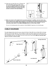
... 59 33 80 62 40. Use the diagram to make sure the cables move smoothly, locate and correct the problem. Do not completely tighten the Locknut; In addition, pull each cable. If the cables do not touch or bind the cables. 5 6 High Cable (61) 7 1 3 4 Carriage Cable (60) 3 2 5 1 4 2 3 5 2 1 3 Bench Cable (58) 4 Low Cable (59) 2 1 16 If the cables have been assembled correctly. Attach the Low Cable (59) to make sure...
... 59 33 80 62 40. Use the diagram to make sure the cables move smoothly, locate and correct the problem. Do not completely tighten the Locknut; In addition, pull each cable. If the cables do not touch or bind the cables. 5 6 High Cable (61) 7 1 3 4 Carriage Cable (60) 3 2 5 1 4 2 3 5 2 1 3 Bench Cable (58) 4 Low Cable (59) 2 1 16 If the cables have been assembled correctly. Attach the Low Cable (59) to make sure...
User Manual
Page 17
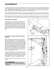
... and move . Then, set the Safety Spotter to the position that will go during the exercise. Engage the Knob into an adjustment hole in the Upright (1, 2) and turn it will stop the barbell at a comfortable height for lifting and replacing the barbell. Note the position of the weight rest and safety spotter on the BENCH ADJUSTMENT CHART, on page 18). Make sure all parts...
... and move . Then, set the Safety Spotter to the position that will go during the exercise. Engage the Knob into an adjustment hole in the Upright (1, 2) and turn it will stop the barbell at a comfortable height for lifting and replacing the barbell. Note the position of the weight rest and safety spotter on the BENCH ADJUSTMENT CHART, on page 18). Make sure all parts...

User Manual
Page 18
... of the barbell and tighten the M8 x 12mm Screw (43). ATTACHING A BARBELL TO THE CABLES To use the Cable Clip (28) to attach the Bench Cable (58) to the Barbell Rings with the Barbell Rings (29). WARNING: Use only an Olympic barbell (not included) with two Cable Clips (28). ATTACHING THE BENCH TO THE RACK To perform bench and leg lever exercises, the weight bench must be lifted...
... of the barbell and tighten the M8 x 12mm Screw (43). ATTACHING A BARBELL TO THE CABLES To use the Cable Clip (28) to attach the Bench Cable (58) to the Barbell Rings with the Barbell Rings (29). WARNING: Use only an Olympic barbell (not included) with two Cable Clips (28). ATTACHING THE BENCH TO THE RACK To perform bench and leg lever exercises, the weight bench must be lifted...

User Manual
Page 19
... high cable (see ATTACHING THE BENCH TO THE RACK and ATTACHING A BARBELL TO THE CABLES on the back of turns. ATTACHING THE ACCESSORIES TO THE CABLES To use the Power Assist Legs (20, 21), attach the bench to the rack and a barbell to the lower set of holes in the same manner. TIGHTENING THE CABLES A Woven cable, the type of holes in the cables, tighten them . Remove the M10 x 45mm Bolt (76...
... high cable (see ATTACHING THE BENCH TO THE RACK and ATTACHING A BARBELL TO THE CABLES on the back of turns. ATTACHING THE ACCESSORIES TO THE CABLES To use the Power Assist Legs (20, 21), attach the bench to the rack and a barbell to the lower set of holes in the same manner. TIGHTENING THE CABLES A Woven cable, the type of holes in the cables, tighten them . Remove the M10 x 45mm Bolt (76...
User Manual
Page 20
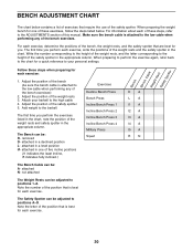
... back to the high cable 4. Exercises Decline Bench Press Bench Press Incline Bench Press 1 Incline Bench Press 2 Incline Bench Press 3 Incline Bench Press 4 Military Press Squat DA LA I1 A I2 A I3 A I4 A I5 A RN 20 attached in a level position I#- BENCH ADJUSTMENT CHART The chart below . attached in a declined position L- attached N- Add weight to positions 1-8. not attached The Weight Rests can be adjusted to the barbell. When preparing the weight bench for one of this manual. Bench SBWaeefinegtchyhtSCRpaeobtsltteer Follow these steps when preparing for...
... back to the high cable 4. Exercises Decline Bench Press Bench Press Incline Bench Press 1 Incline Bench Press 2 Incline Bench Press 3 Incline Bench Press 4 Military Press Squat DA LA I1 A I2 A I3 A I4 A I5 A RN 20 attached in a level position I#- BENCH ADJUSTMENT CHART The chart below . attached in a declined position L- attached N- Add weight to positions 1-8. not attached The Weight Rests can be adjusted to the barbell. When preparing the weight bench for one of this manual. Bench SBWaeefinegtchyhtSCRpaeobtsltteer Follow these steps when preparing for...
User Manual
Page 21
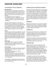
... set " is an efficient way to 10 different exercises. Select a moderate amount of weight and increase the number of repetitions in an uncontrolled manner will find the names of an effective exercise program. Rest for several exercises, and a list of the muscles affected. Cross Training Cross training is a series of repetitions.) The proper amount of weight for each exercise you . Work your workouts, vary the exercises from both weight training...
... set " is an efficient way to 10 different exercises. Select a moderate amount of weight and increase the number of repetitions in an uncontrolled manner will find the names of an effective exercise program. Rest for several exercises, and a list of the muscles affected. Cross Training Cross training is a series of repetitions.) The proper amount of weight for each exercise you . Work your workouts, vary the exercises from both weight training...
User Manual
Page 22
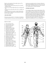
... first couple of this manual can without strain. Remember, the key to achieving the greatest results is an effective way to schedule and record your arms and legs. Rhomboideus (upper back) H P. Brachioradials (forearm) F. Gastrocnemius (back of sets and repetitions completed. List the date, the exercises performed, the weight used to increase flexibility. Sternomastoid (neck) B. Spinae Erectors (lower back) J T. Deltoid (shoulder...
... first couple of this manual can without strain. Remember, the key to achieving the greatest results is an effective way to schedule and record your arms and legs. Rhomboideus (upper back) H P. Brachioradials (forearm) F. Gastrocnemius (back of sets and repetitions completed. List the date, the exercises performed, the weight used to increase flexibility. Sternomastoid (neck) B. Spinae Erectors (lower back) J T. Deltoid (shoulder...
User Manual
Page 24
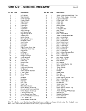
See the back cover of the user's manual for information about ordering replacement parts. Qty. IMBE29910 R1201B Key No. Specifications are subject to change without notice. Description Key No. PART LIST-Model No. Qty. Description 1 1 Left Upright 2 1 Right Upright 3 1 Center Upright 4 1 Center Frame 5 1 Right Frame 6 1 Left Frame 7 2 Pulley Arm 8 1 Pull-up Bar 9 1 Top Frame 10 1 Safety Spotter 11 1 Left Weight Rest 12 1 Right Weight Rest 13 1 Support Leg 14 1 Bench Frame 15 1 Sliding Seat Frame 16...
See the back cover of the user's manual for information about ordering replacement parts. Qty. IMBE29910 R1201B Key No. Specifications are subject to change without notice. Description Key No. PART LIST-Model No. Qty. Description 1 1 Left Upright 2 1 Right Upright 3 1 Center Upright 4 1 Center Frame 5 1 Right Frame 6 1 Left Frame 7 2 Pulley Arm 8 1 Pull-up Bar 9 1 Top Frame 10 1 Safety Spotter 11 1 Left Weight Rest 12 1 Right Weight Rest 13 1 Support Leg 14 1 Bench Frame 15 1 Sliding Seat Frame 16...
User Manual
Page 26
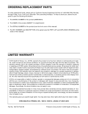
... damage, abuse, misuse, improper or abnormal usage or repairs not provided by ICON. No other warranty beyond that specifically set forth herein. The MODEL NUMBER of the product (IMAGE® 5.0 weight bench) 3. Some states do not allow the exclusion or limitation of incidental or consequential damages. ICON HEALTH & FITNESS, INC., 1500 S. 1000 W., LOGAN, UT 84321-9813 Part No. 180772 R1201B Printed in its scope and...
... damage, abuse, misuse, improper or abnormal usage or repairs not provided by ICON. No other warranty beyond that specifically set forth herein. The MODEL NUMBER of the product (IMAGE® 5.0 weight bench) 3. Some states do not allow the exclusion or limitation of incidental or consequential damages. ICON HEALTH & FITNESS, INC., 1500 S. 1000 W., LOGAN, UT 84321-9813 Part No. 180772 R1201B Printed in its scope and...


