
English Manual
Page 1
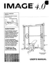
... you complete satisfaction through direct assistance from our factory. MST UTION ead all precautions and Instruclons,..1nthia manual before using, his or futUre refereriCe. IMBE40055 Serial No. Write the serial number in the space above-for reference. The trained technicians on our customer hot line will guarantee you . USER'S MANUAL As a manufacturer, we will provide immediate assistance, free of charge to...
... you complete satisfaction through direct assistance from our factory. MST UTION ead all precautions and Instruclons,..1nthia manual before using, his or futUre refereriCe. IMBE40055 Serial No. Write the serial number in the space above-for reference. The trained technicians on our customer hot line will guarantee you . USER'S MANUAL As a manufacturer, we will provide immediate assistance, free of charge to...

English Manual
Page 2
... specific legal rights. ICON's obligation under normal use , costs of removal, installation or other warranties and any and all freight and other rights which warranty claim is made must be pre-authorized by an ICON authorized service center, products used as store display models. IMAGE4.0 TABLE OF CONTENTS LIMITED WARRANTY IMPORTANT PRECAUTIONS BEFORE YOU BEGIN -ASSEMBLY HOW TO ADJUST THE IMAGE 4.0 ORDERING REPLACEMENT PARTS 2 3 4 - 512 Back Cover Note: A PART IDENTIFICATION CHART and a PART LIST...
... specific legal rights. ICON's obligation under normal use , costs of removal, installation or other warranties and any and all freight and other rights which warranty claim is made must be pre-authorized by an ICON authorized service center, products used as store display models. IMAGE4.0 TABLE OF CONTENTS LIMITED WARRANTY IMPORTANT PRECAUTIONS BEFORE YOU BEGIN -ASSEMBLY HOW TO ADJUST THE IMAGE 4.0 ORDERING REPLACEMENT PARTS 2 3 4 - 512 Back Cover Note: A PART IDENTIFICATION CHART and a PART LIST...

English Manual
Page 3
... away from moving parts. When you feel pain or, d4ziness while,exercising, stop immediately and make sure that the cables remainon the pulleyS at all instructions in this or any worn PartsjrnMediately. 10.Do not place more itnari)50:poUnda::on each weight carriage; Whepperforrhirig Mending exercises, stand Ingefalbp area theils shaded in the iCcomPanying literature before using the weight bench."' partner...
... away from moving parts. When you feel pain or, d4ziness while,exercising, stop immediately and make sure that the cables remainon the pulleyS at all instructions in this or any worn PartsjrnMediately. 10.Do not place more itnari)50:poUnda::on each weight carriage; Whepperforrhirig Mending exercises, stand Ingefalbp area theils shaded in the iCcomPanying literature before using the weight bench."' partner...

English Manual
Page 4
... model number and serial number before Before reading further, please review the drawing using the IMAGES 4.0 Weight Bench. ASSEMBLED DIMENSIONS: Height: 83" Base: 78" x 70" Pull-up Bar High Pulley Barbell Hooks Barbell Racks - To help you to the IMAGES 4.0 (see the front cover of the body. The model number Is IMBE40055. If you for selecting the versatile IMAGE® 4.0 Weight Bench. Safety Stops Weight Carriage Leg Lever Weight Tube 0 0 0 0 O 0 0 0 0 Lock Knob Backrest Weight Storage Tubes Weight Carriage Low Pulley...
... model number and serial number before Before reading further, please review the drawing using the IMAGES 4.0 Weight Bench. ASSEMBLED DIMENSIONS: Height: 83" Base: 78" x 70" Pull-up Bar High Pulley Barbell Hooks Barbell Racks - To help you to the IMAGES 4.0 (see the front cover of the body. The model number Is IMBE40055. If you for selecting the versatile IMAGE® 4.0 Weight Bench. Safety Stops Weight Carriage Leg Lever Weight Tube 0 0 0 0 O 0 0 0 0 Lock Knob Backrest Weight Storage Tubes Weight Carriage Low Pulley...

English Manual
Page 5
... parts used in assembly, use the PART IDENTIFICATION CHART located In the center of this manual. Before beginning assembly, be sure that all parts of ratchet wrenches. 1. Press a 2" x 2 1/2" Outer Cap (13) onto each Short Stabilizer (19). 2 Attach both Short Stabilizers (19) to the Base (54) with two M10 x 70mm Bolts (5) and two M10 Nylon Locknuts (1). • 19 0 13 5 13 13 0 0 0 0 19 54 5 Attach the Rear...
... parts used in assembly, use the PART IDENTIFICATION CHART located In the center of this manual. Before beginning assembly, be sure that all parts of ratchet wrenches. 1. Press a 2" x 2 1/2" Outer Cap (13) onto each Short Stabilizer (19). 2 Attach both Short Stabilizers (19) to the Base (54) with two M10 x 70mm Bolts (5) and two M10 Nylon Locknuts (1). • 19 0 13 5 13 13 0 0 0 0 19 54 5 Attach the Rear...

English Manual
Page 6
...the Backrest (15). Attach the Backrest (15) to the Base (54) 3 with four M6 x 40mm Bolts (4). Lubricate the two M10 x 190mm Bolts (58). Do not overtighten the Nylon Locknut. 3. Press 1" Square Inner Caps (57) into the ends of the Backrest Rails (16). 4 Turn the Backrest Rails (...the Bolt. Tighten the four M6 x 40mm Bolts (4). 15 5 16 1 21 Flat End 15 58 Lubricate 54 6 Do not overtIghten the Nylon Locknut. Attach the Backrest Rails to pivot freely. 4. Do 16 not tighten the Bolts yet. 53 54 0 4 57 Holes 5. Tighten an M10 Nylon Locknut (1) onto the Bolt. See step ...
...the Backrest (15). Attach the Backrest (15) to the Base (54) 3 with four M6 x 40mm Bolts (4). Lubricate the two M10 x 190mm Bolts (58). Do not overtighten the Nylon Locknut. 3. Press 1" Square Inner Caps (57) into the ends of the Backrest Rails (16). 4 Turn the Backrest Rails (...the Bolt. Tighten the four M6 x 40mm Bolts (4). 15 5 16 1 21 Flat End 15 58 Lubricate 54 6 Do not overtIghten the Nylon Locknut. Attach the Backrest Rails to pivot freely. 4. Do 16 not tighten the Bolts yet. 53 54 0 4 57 Holes 5. Tighten an M10 Nylon Locknut (1) onto the Bolt. See step ...

English Manual
Page 7
...6" Foam Pad (10) onto each end of the 54 18 11 10 Pad Tube. Lubricate the M12 x 95mm Bolt (59). Nylon l ocknot. 7 Lubricate N 59 60 17 0 18 46 ,18 49 11)- .41 1 6 2 6 5 46 12 17 8. N 0 65 67 1 7 Press a 3/4" Round Inner Cap (65) into the indicated tube on the Base (54). ... the Weight Tube (46). Be sure the Weight Tube Is Inserted so that It Is angled as shown In the Inset drawing. Attach the Seat (14) to the Base (54) with the M12 x 95mm Bolt and the M12 Nylon Locknut (60). Press a Leg Lever Bumper (49) into the Leg Lever (18). Attach the Leg Lever ...
...6" Foam Pad (10) onto each end of the 54 18 11 10 Pad Tube. Lubricate the M12 x 95mm Bolt (59). Nylon l ocknot. 7 Lubricate N 59 60 17 0 18 46 ,18 49 11)- .41 1 6 2 6 5 46 12 17 8. N 0 65 67 1 7 Press a 3/4" Round Inner Cap (65) into the indicated tube on the Base (54). ... the Weight Tube (46). Be sure the Weight Tube Is Inserted so that It Is angled as shown In the Inset drawing. Attach the Seat (14) to the Base (54) with the M12 x 95mm Bolt and the M12 Nylon Locknut (60). Press a Leg Lever Bumper (49) into the Leg Lever (18). Attach the Leg Lever ...

English Manual
Page 8
...13 13 26 8 10. Slide four Weight Carriage Rollers (44) onto the Weight Carriage. Attach the Left Base (25) to the Joiner Bracket 9 (27) with an 10 M10 x 50mm Bolt (39). Press a 1" Round Inner Cap (12) into the Right Base (26). Attach a 4 1/2" Pulley (61) and a Cable Trap (40) to the Joiner Bracket...Do not tiahten the Bolt yet. 9. The Weight Carriage Rollers must be turned as shown in the inset drawing. 44 Assemble the other Weight Carriage (37) in the same manner. 61. 0 37 0 Beveled edge must face this direction I 44-[ 37 61 40 39 12 8 Attach the Right Base (...
...13 13 26 8 10. Slide four Weight Carriage Rollers (44) onto the Weight Carriage. Attach the Left Base (25) to the Joiner Bracket 9 (27) with an 10 M10 x 50mm Bolt (39). Press a 1" Round Inner Cap (12) into the Right Base (26). Attach a 4 1/2" Pulley (61) and a Cable Trap (40) to the Joiner Bracket...Do not tiahten the Bolt yet. 9. The Weight Carriage Rollers must be turned as shown in the inset drawing. 44 Assemble the other Weight Carriage (37) in the same manner. 61. 0 37 0 Beveled edge must face this direction I 44-[ 37 61 40 39 12 8 Attach the Right Base (...

English Manual
Page 9
... each M10 x 80mm Carriage Bolt. Slide a 11 Weight Carriage (37) into each Barbell Upright (38, 41). Slot Assemble the other Storage Tube (68) to the bracket on the Right Base (26) with an M10 x 65mm Bolt (7) and an M-10 Nylon Locknut (1). Insert a Safety Stop (23) into the Weight Upright. The Roller Bushings must face this"----a" direction 31 9 Be sure that the...
... each M10 x 80mm Carriage Bolt. Slide a 11 Weight Carriage (37) into each Barbell Upright (38, 41). Slot Assemble the other Storage Tube (68) to the bracket on the Right Base (26) with an M10 x 65mm Bolt (7) and an M-10 Nylon Locknut (1). Insert a Safety Stop (23) into the Weight Upright. The Roller Bushings must face this"----a" direction 31 9 Be sure that the...

English Manual
Page 10
.... Attach each Weight Upright (42) to the Top Frame with two M10 x 90mm Bolts (9) and two M10 Washers (6). Press two 1" Round Inner Caps (12) into the Top Frame. Tighten the four M10 Nylon Locknuts (1) used in the same manner. 14 C 24 Lubricate • Welded Stop 28 0 28 C or C 29 6 26 29 Welded Stop Lubricate Lower Pulley Upper Pulley Bracket Bracket Welded Stop O Welded Stop 10 Lubricate the...
.... Attach each Weight Upright (42) to the Top Frame with two M10 x 90mm Bolts (9) and two M10 Washers (6). Press two 1" Round Inner Caps (12) into the Top Frame. Tighten the four M10 Nylon Locknuts (1) used in the same manner. 14 C 24 Lubricate • Welded Stop 28 0 28 C or C 29 6 26 29 Welded Stop Lubricate Lower Pulley Upper Pulley Bracket Bracket Welded Stop O Welded Stop 10 Lubricate the...

English Manual
Page 11
... Pulley. The Cable must be between the Pulley and the Top Frame (24). Note: The Pulley fits tightly into the Pulley Bracket. The Cable must be described in HOW TO ADJUST THE IMAGE 4.0, beginning on page 12 of the left Weight Uoriaht (42) with an M10 x 45mm Bolt (39) and an M10 Nylon Locknut (1). Attach the Pulley to the upper end of this step...
... Pulley. The Cable must be between the Pulley and the Top Frame (24). Note: The Pulley fits tightly into the Pulley Bracket. The Cable must be described in HOW TO ADJUST THE IMAGE 4.0, beginning on page 12 of the left Weight Uoriaht (42) with an M10 x 45mm Bolt (39) and an M10 Nylon Locknut (1). Attach the Pulley to the upper end of this step...

English Manual
Page 12
...be rotated so that the Safety Stops are below the Barbell Racks (31) and are at the same time. HOW TO ADJUST THE IMAGE® 4.0 The instructions below describe how each part of the IMAGE® 4.0 can be used with your own olympic barbell (...attach your barbell, first remove the olympic adapter sleeve from one of Barbell Adapters onto your barbell. Try to see the correct form for each Barbell Hook into the Barbell Racks (31). Tighten an M6 x 16mm Set Screw (52) into each pair of the large holes in the Barbell Uprights (38, 41). Refer to the EXERCISE GUIDE accompanying this manual...
...be rotated so that the Safety Stops are below the Barbell Racks (31) and are at the same time. HOW TO ADJUST THE IMAGE® 4.0 The instructions below describe how each part of the IMAGE® 4.0 can be used with your own olympic barbell (...attach your barbell, first remove the olympic adapter sleeve from one of Barbell Adapters onto your barbell. Try to see the correct form for each Barbell Hook into the Barbell Racks (31). Tighten an M6 x 16mm Set Screw (52) into each pair of the large holes in the Barbell Uprights (38, 41). Refer to the EXERCISE GUIDE accompanying this manual...

English Manual
Page 13
... from the Barbell Uprights. ATTACHING WEIGHTS TO THE WEIGHT CARRIAGES To use the upper or lower pulley stations, slide the desired amount of weight (not included) onto the weight post of one decline position, and two incline positions. Raise or lower the Backrest to use a Weight Adapter (48). USING THE BARBELL RACKS To use the Barbell Racks (31), first insert the Safety Stops (23) into a set of the...
... from the Barbell Uprights. ATTACHING WEIGHTS TO THE WEIGHT CARRIAGES To use the upper or lower pulley stations, slide the desired amount of weight (not included) onto the weight post of one decline position, and two incline positions. Raise or lower the Backrest to use a Weight Adapter (48). USING THE BARBELL RACKS To use the Barbell Racks (31), first insert the Safety Stops (23) into a set of the...

English Manual
Page 14
ATTACHING THE HANDLES TO THE UPPER A AND LOWER PULLEY STATIONS To use the upper pulley station (see drawing A) or lower pulley station (see drawing B), weight must first be attached to the Cables (45) in the same manner. The Handles (36) can be attached to the Cables (45) with the Cable Clips (64) as shown. The Ankle Strap (55) can be placed on the weight carriages (see ATTACHING WEIGHTS TO THE WEIGHT CARRIAGES on page 13). B 55 36 64 45 45 36 55 14
ATTACHING THE HANDLES TO THE UPPER A AND LOWER PULLEY STATIONS To use the upper pulley station (see drawing A) or lower pulley station (see drawing B), weight must first be attached to the Cables (45) in the same manner. The Handles (36) can be attached to the Cables (45) with the Cable Clips (64) as shown. The Ankle Strap (55) can be placed on the weight carriages (see ATTACHING WEIGHTS TO THE WEIGHT CARRIAGES on page 13). B 55 36 64 45 45 36 55 14

English Manual
Page 16
... of the product (IMAGE® 4.0 Weight Bench). • The SERIAL NUMBER of the product (see the front cover of this manual). _The KEY_LsIUMI3Elland_DESCF3REION_of_the_part(s)_(seathe_PART-LIST/EXPLODED_DRAW-ING-attached-to the center of this manual). Part No. 135831 R1296A Printed in China © 1996 ICON Health & Fitness, Inc. until 6 p.m. Mountain Time (excluding holidays). ORDERING REPLACEMENT PARTS To order replacement parts, simply call our Customer Service Department toll-free at 1-800-999...
... of the product (IMAGE® 4.0 Weight Bench). • The SERIAL NUMBER of the product (see the front cover of this manual). _The KEY_LsIUMI3Elland_DESCF3REION_of_the_part(s)_(seathe_PART-LIST/EXPLODED_DRAW-ING-attached-to the center of this manual). Part No. 135831 R1296A Printed in China © 1996 ICON Health & Fitness, Inc. until 6 p.m. Mountain Time (excluding holidays). ORDERING REPLACEMENT PARTS To order replacement parts, simply call our Customer Service Department toll-free at 1-800-999...

English Manual
Page 17
IMBE40055 R1296A Important: Some parts may have been pre-assembled for assembly. REMOVE THIS PART IDENTIFICATION CHART FROM THE MANUAL This chart is provided to see If It has been pre-assembled. If you cannot find a part In the parts bags, check to help you identify the small parts used in parenthesis below each part refers to the quantity needed for shipping purposes. The second number refers to the key number of the part. The number in assembly.
IMBE40055 R1296A Important: Some parts may have been pre-assembled for assembly. REMOVE THIS PART IDENTIFICATION CHART FROM THE MANUAL This chart is provided to see If It has been pre-assembled. If you cannot find a part In the parts bags, check to help you identify the small parts used in parenthesis below each part refers to the quantity needed for shipping purposes. The second number refers to the key number of the part. The number in assembly.

English Manual
Page 22
... Seat Backrest Backrest Rail 2" Square Inner Cap Leg Lever Short Stabilizer 3" Round Inner Cap Adjustment Tube Rear Stabilizer Safety Stop Top Frame Left Base Right Base Joiner Bracket Upper Pulley Bracket Lower Pulley Bracket Roller Bushing Barbell Rack Left Barbell Hook M6 x 65mm Bolt Right Barbell Hook 3 1/2" Pulley Handle Weight Carriage Right Barbell Upright M10 x 50mm Bolt Cable Trap Left Barbell Upright Weight Upright M10 x 140mm Bolt Weight Carriage Roller Cable Key No. PART LIST Model...
... Seat Backrest Backrest Rail 2" Square Inner Cap Leg Lever Short Stabilizer 3" Round Inner Cap Adjustment Tube Rear Stabilizer Safety Stop Top Frame Left Base Right Base Joiner Bracket Upper Pulley Bracket Lower Pulley Bracket Roller Bushing Barbell Rack Left Barbell Hook M6 x 65mm Bolt Right Barbell Hook 3 1/2" Pulley Handle Weight Carriage Right Barbell Upright M10 x 50mm Bolt Cable Trap Left Barbell Upright Weight Upright M10 x 140mm Bolt Weight Carriage Roller Cable Key No. PART LIST Model...


