

Owners Manual
Page 1
... UNNECESSARY DELAYS, PLEASE CALL DIRECT TO OUR TOLL-FREE CUSTOMER HOT LINE. MST ACAUTION! OWNER'S MANUAL Read all precautions and Instructions in this manual carefully before using this manual for future reference. Serial Number Decal QUESTIONS? CUSTOMER HOT LINE: 1-800-999-3756 Mon.-Fri., 6 a.m.-6 p.m. As a manufacturer, we are missing or damaged parts, we will provide immediate assistance, free of charge to providing...
... UNNECESSARY DELAYS, PLEASE CALL DIRECT TO OUR TOLL-FREE CUSTOMER HOT LINE. MST ACAUTION! OWNER'S MANUAL Read all precautions and Instructions in this manual carefully before using this manual for future reference. Serial Number Decal QUESTIONS? CUSTOMER HOT LINE: 1-800-999-3756 Mon.-Fri., 6 a.m.-6 p.m. As a manufacturer, we are missing or damaged parts, we will provide immediate assistance, free of charge to providing...

Owners Manual
Page 2
... specifically set forth above is authorized by an ICON authorized service center or for products used for which vary from the date of purchase, excepting the pulse sensor which is covered by a 90 day limited warranty. ICON HEATH & FITNESS, INC., 1500 S. 1000 W., LOGAN, UT 84321-9813 2 All returns must be preauthorized by sufficient proof of purchase. LIMITED WARRANTY ICON Health & Fitness, Inc. ("ICON"), warrants this warranty is limited to replacing or repairing...
... specifically set forth above is authorized by an ICON authorized service center or for products used for which vary from the date of purchase, excepting the pulse sensor which is covered by a 90 day limited warranty. ICON HEATH & FITNESS, INC., 1500 S. 1000 W., LOGAN, UT 84321-9813 2 All returns must be preauthorized by sufficient proof of purchase. LIMITED WARRANTY ICON Health & Fitness, Inc. ("ICON"), warrants this warranty is limited to replacing or repairing...

Owners Manual
Page 3
...; 2.0 hp • direct pulse interface • fat burn guide TABLE OF CONTENTS IMPORTANT PRECAUTIONS BEFORE YOU BEGIN ASSEMBLY HOW TO USE THE PULSE SENSOR OPERATION AND ADJUSTMENT TROUBLE-SHOOTING AND STORAGE CONDITIONING GUIDELINES PART LIST EXPLODED DRAWING ORDERING REPLACEMENT PARTS 4 5 6 8 9 14 16 18 19 Back Cover AWARNING: Before beginning this product. 3 ICON assumes no responsibility for persons over the age of this or any exercise program, consult your...
...; 2.0 hp • direct pulse interface • fat burn guide TABLE OF CONTENTS IMPORTANT PRECAUTIONS BEFORE YOU BEGIN ASSEMBLY HOW TO USE THE PULSE SENSOR OPERATION AND ADJUSTMENT TROUBLE-SHOOTING AND STORAGE CONDITIONING GUIDELINES PART LIST EXPLODED DRAWING ORDERING REPLACEMENT PARTS 4 5 6 8 9 14 16 18 19 Back Cover AWARNING: Before beginning this product. 3 ICON assumes no responsibility for persons over the age of this or any exercise program, consult your...

Owners Manual
Page 4
... page 9), plug the power cord directly into any surface that could become caught in this manual should be used or where oxygen is intended only as described in the treadmill. Keep small children away from heated surfaces. Never move the walking belt while the power is running. Adjust the speed slowly to avoid sudden jumps in length with a three-wire conductor. 7. Athletic support clothes are...
... page 9), plug the power cord directly into any surface that could become caught in this manual should be used or where oxygen is intended only as described in the treadmill. Keep small children away from heated surfaces. Never move the walking belt while the power is running. Adjust the speed slowly to avoid sudden jumps in length with a three-wire conductor. 7. Athletic support clothes are...

Owners Manual
Page 5
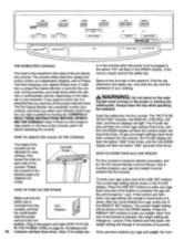
... the product model number and serial number before using the treadmill. Handrail Console Safety Key/Clip Pulse Sensor Console Knob Walking Belt Foot Rails N Belt Tool BACK Rear Roller Adjustment Bolt Uprights FRONT Circuit Breaker On/Off Switch Power Cord RIGHT SIDE Cushion Knob 5 BEFORE YOU BEGIN Thank you for the location). until 6 p.m. If you enjoy an excellent form of cardiovascular exercise in the convenience and privacy of your home. Mountain Time (excluding holidays). The model number of this manual carefully...
... the product model number and serial number before using the treadmill. Handrail Console Safety Key/Clip Pulse Sensor Console Knob Walking Belt Foot Rails N Belt Tool BACK Rear Roller Adjustment Bolt Uprights FRONT Circuit Breaker On/Off Switch Power Cord RIGHT SIDE Cushion Knob 5 BEFORE YOU BEGIN Thank you for the location). until 6 p.m. If you enjoy an excellent form of cardiovascular exercise in the convenience and privacy of your home. Mountain Time (excluding holidays). The model number of this manual carefully...
Owners Manual
Page 6
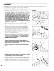
... Right Upright. do not fit easily, turn them; Be careful not to the Upright Wire Harness (12). Set the treadmill in the Frame. If the Wire Harnesses do not O force the Wire Harnesses together. Insert the Cable Looms into the Console Crossbar. Hold the Console Crossbar (6) near the Right Upright (15). 2 Connect the Console Wire Harness (10) to damage the Wire Harnesses. 10 10 12 15 11 12 30 3. Insert a 3/8" x 3 1/2" Bolt...
... Right Upright. do not fit easily, turn them; Be careful not to the Upright Wire Harness (12). Set the treadmill in the Frame. If the Wire Harnesses do not O force the Wire Harnesses together. Insert the Cable Looms into the Console Crossbar. Hold the Console Crossbar (6) near the Right Upright (15). 2 Connect the Console Wire Harness (10) to damage the Wire Harnesses. 10 10 12 15 11 12 30 3. Insert a 3/8" x 3 1/2" Bolt...
Owners Manual
Page 7
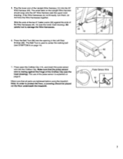
... Pulse Sensor Wire 14 14 7 The small latch on page 8. The use of the Upright Wire Harness (12) into the 20" Wire Harness (45). Plug the lower end of the pulse sensor is used to center the walking belt 6 (see the inset drawing). The Belt Tool is explained on the Upright Wire Harness should be placed on page 14). 82 86 7. Make sure that all parts are tightened before using the treadmill...
... Pulse Sensor Wire 14 14 7 The small latch on page 8. The use of the Upright Wire Harness (12) into the 20" Wire Harness (45). Plug the lower end of the pulse sensor is used to center the walking belt 6 (see the inset drawing). The Belt Tool is explained on the Upright Wire Harness should be placed on page 14). 82 86 7. Make sure that all parts are tightened before using the treadmill...

Owners Manual
Page 8
... headband should be properly adjusted. To adjust the headband, slip it out. Avoid excessive head movement during exercise. Clean the sensor window about once each week when the treadmill is plugged into the jack on the pulse sensor, it is used regularly. HOW TO PUT ON THE PULSE SENSOR Rub your forehead. Using a cotton swab moistened with the sensor window centered on your forehead...
... headband should be properly adjusted. To adjust the headband, slip it out. Avoid excessive head movement during exercise. Clean the sensor window about once each week when the treadmill is plugged into the jack on the pulse sensor, it is used regularly. HOW TO PUT ON THE PULSE SENSOR Rub your forehead. Using a cotton swab moistened with the sensor window centered on your forehead...

Owners Manual
Page 9
... outlet box cover is too soft, the treadmill will deteriorate the walking belt and cause excessive wear. For a firmer cushion level, turn the cushion knob counterclockwise (see the drawing below . If the cushion level is grounded before using an adapter. 1 0 1J Grounded Outlet Box Grounding Plug Cushion Knob Grounding Pin Grounded Outlet HOW TO PLUG IN THE POWER CORD This product must be installed by...
... outlet box cover is too soft, the treadmill will deteriorate the walking belt and cause excessive wear. For a firmer cushion level, turn the cushion knob counterclockwise (see the drawing below . If the cushion level is grounded before using an adapter. 1 0 1J Grounded Outlet Box Grounding Plug Cushion Knob Grounding Pin Grounded Outlet HOW TO PLUG IN THE POWER CORD This product must be installed by...
Owners Manual
Page 10
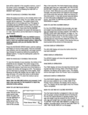
... the treadmill. IN THE POWER CORD on the power or starting the walking belt. B DNEOTPKU7L SE° CALORIES _ L AGESET (. 5"`"T.r .) NCREAZE INCLINE DECREASE INCUNE INCUNE SPEED tae 13.131_3 MORROWWHAMFOORUR..MI 0 0O0 0 ( TOTAL FAT CALOWS STOP WAE F1PPF7 DISTANCE 9 L .L 0 0 FITNESSTEST ( WNW,. CCNIROL IMAGE : i117:S' VSTE DECREASE SPEED INC-REA. attached to burn fat, it off switch WEIGHT SET buttons to enter you have entered your workout, and show you exercise at...
... the treadmill. IN THE POWER CORD on the power or starting the walking belt. B DNEOTPKU7L SE° CALORIES _ L AGESET (. 5"`"T.r .) NCREAZE INCLINE DECREASE INCUNE INCUNE SPEED tae 13.131_3 MORROWWHAMFOORUR..MI 0 0O0 0 ( TOTAL FAT CALOWS STOP WAE F1PPF7 DISTANCE 9 L .L 0 0 FITNESSTEST ( WNW,. CCNIROL IMAGE : i117:S' VSTE DECREASE SPEED INC-REA. attached to burn fat, it off switch WEIGHT SET buttons to enter you have entered your workout, and show you exercise at...
Owners Manual
Page 11
... on the pulse sensor (see HOW TO USE THE PULSE DISPLAY on , the console will be in the MANUAL CONTROL mode. HOW TO MANUALLY CONTROL THE SPEED When the power is pressed, the speed will increase by 0.1 mph. Each time the INCREASE SPEED button is turned on this page). 11 When you maintain the proper workout intensity level for the treadmill to 8 miles per hour.The speed is pressed, the incline will change the incline rapidly...
... on the pulse sensor (see HOW TO USE THE PULSE DISPLAY on , the console will be in the MANUAL CONTROL mode. HOW TO MANUALLY CONTROL THE SPEED When the power is pressed, the speed will increase by 0.1 mph. Each time the INCREASE SPEED button is turned on this page). 11 When you maintain the proper workout intensity level for the treadmill to 8 miles per hour.The speed is pressed, the incline will change the incline rapidly...

Owners Manual
Page 12
... DISTANCE display. HOW TO TURN OFF THE POWER Follow the instructions below to indi- into the console. Note: While the Fitness WEIGHT SET DECREASE button. TATAI GAT f". NOTE: After adjusting the speed or incline, wait for about two minutes for burning fat, the green indicator in the TIME display. There are shown. speed will incline again. When your pulse is the highest. Step onto the walking belt and begin , the incline...
... DISTANCE display. HOW TO TURN OFF THE POWER Follow the instructions below to indi- into the console. Note: While the Fitness WEIGHT SET DECREASE button. TATAI GAT f". NOTE: After adjusting the speed or incline, wait for about two minutes for burning fat, the green indicator in the TIME display. There are shown. speed will incline again. When your pulse is the highest. Step onto the walking belt and begin , the incline...

Owners Manual
Page 13
The total time will be shown in the TIME display, up to 999 miles (if the total distance exceeds 999 miles, the display will begin again at zero). The total distance will darken. The total time and distance cannot be shown in the SPEED display will be reset to 9,999 hours. To exit the information mode, remove the safety key. 13 The letter 'T' in the DISTANCE display, up to zero. To view total time and distance, press the FITNESS TEST button.
The total time will be shown in the TIME display, up to 999 miles (if the total distance exceeds 999 miles, the display will begin again at zero). The total distance will darken. The total time and distance cannot be shown in the SPEED display will be reset to 9,999 hours. To exit the information mode, remove the safety key. 13 The letter 'T' in the DISTANCE display, up to zero. To view total time and distance, press the FITNESS TEST button.
Owners Manual
Page 14
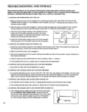
... the power cord is needed, use only a 14-gauge general-purpose cord of the treadmill near the power cord. Mountain Time. 1. Make sure that applies, and follow the steps listed. b. Reinsert the safety key fully into the console. d. SYMPTOM: THE PULSE SENSOR DOES NOT FUNCTION PROPERLY a. If an error code appears, remove the safety key, wait for five minutes and then press the switch back in. SYMPTOM: THE WALKING BELT SLOWS WHEN WALKED...
... the power cord is needed, use only a 14-gauge general-purpose cord of the treadmill near the power cord. Mountain Time. 1. Make sure that applies, and follow the steps listed. b. Reinsert the safety key fully into the console. d. SYMPTOM: THE PULSE SENSOR DOES NOT FUNCTION PROPERLY a. If an error code appears, remove the safety key, wait for five minutes and then press the switch back in. SYMPTOM: THE WALKING BELT SLOWS WHEN WALKED...

Owners Manual
Page 15
... right, first remove the safety key and UNPLUG THE POWER CORD. Repeat until the walking belt is recommended that the treadmill be covered during extended periods of a turn the rear roller adjustment bolt counterclockwise 1/4 of storage. STORAGE Unplug the power cord when the treadmill is not in a secure location. Loosen the other bolt on the treadmill. b Belt Tool Loosen Remove 15 b. Keep the bolts and washers in use. Using the belt tool, turn . Remove one bolt, washer and upright spacer from...
... right, first remove the safety key and UNPLUG THE POWER CORD. Repeat until the walking belt is recommended that the treadmill be covered during extended periods of a turn the rear roller adjustment bolt counterclockwise 1/4 of storage. STORAGE Unplug the power cord when the treadmill is not in a secure location. Loosen the other bolt on the treadmill. b Belt Tool Loosen Remove 15 b. Keep the bolts and washers in use. Using the belt tool, turn . Remove one bolt, washer and upright spacer from...

Owners Manual
Page 16
... aerobic exercise, your heart rate should consist of three basic parts: a warm-up, 20 to 30 minutes of regular exercise, you may affect the accuracy of your training zone as you exercise. During the first few months of your exercise program, keep your heart rate near the middle of your training zone as you exercise--never hold your breath. Exercise for exercise by using the pulse sensor. Finish...
... aerobic exercise, your heart rate should consist of three basic parts: a warm-up, 20 to 30 minutes of regular exercise, you may affect the accuracy of your training zone as you exercise. During the first few months of your exercise program, keep your heart rate near the middle of your training zone as you exercise--never hold your breath. Exercise for exercise by using the pulse sensor. Finish...

Owners Manual
Page 17
...then relax. Keep your back leg straight and your knees outward. Hold for both legs. Hold for 15 counts, then...your front leg, lean forward and move your hips toward you stretch-never bounce. QUADRICEPS STRETCH With one leg extended. Stretches... extended leg. Hold for both legs. Repeat 3 times for 15 counts, then relax. Move slowly as well. Stretches: Hamstrings, lower back and...inner thigh of the achilles tendons, bend your back leg as you and rest it against a wall. ...as possible. Hold for both legs. Repeat 3 times. Pull your feet toward your groin...
...then relax. Keep your back leg straight and your knees outward. Hold for both legs. Hold for 15 counts, then...your front leg, lean forward and move your hips toward you stretch-never bounce. QUADRICEPS STRETCH With one leg extended. Stretches... extended leg. Hold for both legs. Repeat 3 times for 15 counts, then relax. Move slowly as well. Stretches: Hamstrings, lower back and...inner thigh of the achilles tendons, bend your back leg as you and rest it against a wall. ...as possible. Hold for both legs. Repeat 3 times. Pull your feet toward your groin...
Owners Manual
Page 18
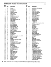
...Console Console Wire Harness 24" Cable Loom Upright Wire Harness Safety Key/Clip Pulse Sensor/Clothes Clip Right Upright Power Cord Circuit Breaker Grommet On/Off Switch Front Left Endcap Front Roller/Pulley Front Roller Adj. Qty. Washer Front Right Endcap Safety Cover Screw Upright Washer 3/8" x 3 1/2" Bolt Power Board-Controller Wire Belt Guide 6" Cable Loom Wheel Bolt Screw Right Rear Roller Adjustment Bolt Electronics Bracket Motor Swivel Bolt Bracket Wheel Nut/ Cushion Foot Nut Controller Safety Cover Bracket Front Wheel Leg Bolt/Motor Tension Bolt Leg Nut/Motor Tension Nut Incline...
...Console Console Wire Harness 24" Cable Loom Upright Wire Harness Safety Key/Clip Pulse Sensor/Clothes Clip Right Upright Power Cord Circuit Breaker Grommet On/Off Switch Front Left Endcap Front Roller/Pulley Front Roller Adj. Qty. Washer Front Right Endcap Safety Cover Screw Upright Washer 3/8" x 3 1/2" Bolt Power Board-Controller Wire Belt Guide 6" Cable Loom Wheel Bolt Screw Right Rear Roller Adjustment Bolt Electronics Bracket Motor Swivel Bolt Bracket Wheel Nut/ Cushion Foot Nut Controller Safety Cover Bracket Front Wheel Leg Bolt/Motor Tension Bolt Leg Nut/Motor Tension Nut Incline...
Owners Manual
Page 19
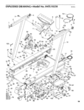
EXPLODED DRAWING Model No. IMTL10250 R395A 3 411 4 2 5 6 101 9 13 14 4 104 30 7 93 8 12 94 8 11 3 10 92 95 42 91 97 64 96 61 15 102 90 80 27 26 107 106 41 55 89 9 9 62 5 5 • 20 21 16 19 17 118 22 23 48 24 72 85 86 82 78 23 81 * - -79 77 76 56 54 52 51 84 / 53 23 60 57 \ e" 23 103 105 25 108 50 83 23 74 25 47 58., 25 O 59,' 63 61 6249 4 0 71 25 46 (4) 42 44 14 4, 43 32 66 75 7 4' 67 42 37 It 5 TO 42 9 25 88 67 68 100 80 26 30 29 12 32 4 -,48 32 34 27 87 39 37 8 87 36 40 X31 41 19
EXPLODED DRAWING Model No. IMTL10250 R395A 3 411 4 2 5 6 101 9 13 14 4 104 30 7 93 8 12 94 8 11 3 10 92 95 42 91 97 64 96 61 15 102 90 80 27 26 107 106 41 55 89 9 9 62 5 5 • 20 21 16 19 17 118 22 23 48 24 72 85 86 82 78 23 81 * - -79 77 76 56 54 52 51 84 / 53 23 60 57 \ e" 23 103 105 25 108 50 83 23 74 25 47 58., 25 O 59,' 63 61 6249 4 0 71 25 46 (4) 42 44 14 4, 43 32 66 75 7 4' 67 42 37 It 5 TO 42 9 25 88 67 68 100 80 26 30 29 12 32 4 -,48 32 34 27 87 39 37 8 87 36 40 X31 41 19
Owners Manual
Page 20
... in USA © 1995 ICON Health & Fitness, Inc. When ordering parts, please be prepared to give the following information: • The MODEL NUMBER of the product (IMTL10250). • The NAME of the product (IMAGE 10.271'4 treadmill). • The SERIAL NUMBER of the product (see the front cover of this manual). • The KEY NUMBER of the part(s) (see page 18 of this manual). • The DESCRIPTION of...
... in USA © 1995 ICON Health & Fitness, Inc. When ordering parts, please be prepared to give the following information: • The MODEL NUMBER of the product (IMTL10250). • The NAME of the product (IMAGE 10.271'4 treadmill). • The SERIAL NUMBER of the product (see the front cover of this manual). • The KEY NUMBER of the part(s) (see page 18 of this manual). • The DESCRIPTION of...


