Instruction Manual
Page 1
COMMUNICATIONS RECEIVER iR9500 Instruction Manual A-6553H-1EX-q Printed in Japan © 2007 Icom Inc.
COMMUNICATIONS RECEIVER iR9500 Instruction Manual A-6553H-1EX-q Printed in Japan © 2007 Icom Inc.
Instruction Manual
Page 2
... LCD ❍ Built-in your responsibility to comply with export regulations may occur. FOREWORD Thank you for the IC-R9500. D FEATURES ❍ Ultimate receiver performance: 109 dB wide dynamic range and third-order intercept (IP3) of Icom Incorporated (Japan) in this product, it is your country. If disregarded, inconvenience only. ABOUT RE-EXPORTING THIS...
... LCD ❍ Built-in your responsibility to comply with export regulations may occur. FOREWORD Thank you for the IC-R9500. D FEATURES ❍ Ultimate receiver performance: 109 dB wide dynamic range and third-order intercept (IP3) of Icom Incorporated (Japan) in this product, it is your country. If disregarded, inconvenience only. ABOUT RE-EXPORTING THIS...
Instruction Manual
Page 3
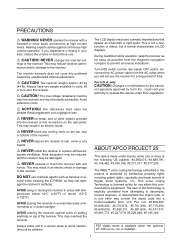
... caused by intellectual property rights including patent rights, copyrights and trade secrets of the receiver. equate ventilation. cohol when cleaning the IC-R9500, as small dark or light spots. The receiver weighs approx. 20 kg (44 lb). Always have cosmetic imperfections that appear as they...the AC power cable from attempting to operate this device, not expressly approved by Icom Inc., could void your ears, reduce the volume or discontinue use the receiver for use chemical agents such as possible from the magnetic navigation compass to avoid inadvertent...
... caused by intellectual property rights including patent rights, copyrights and trade secrets of the receiver. equate ventilation. cohol when cleaning the IC-R9500, as small dark or light spots. The receiver weighs approx. 20 kg (44 lb). Always have cosmetic imperfections that appear as they...the AC power cable from attempting to operate this device, not expressly approved by Icom Inc., could void your ears, reduce the volume or discontinue use the receiver for use chemical agents such as possible from the magnetic navigation compass to avoid inadvertent...
Instruction Manual
Page 5
... gain adjustment 3-8 ■ Squelch level adjustment 3-8 ■ Audio tone adjustment 3-9 D Treble level adjustment 3-9 D Bass level adjustment 3-9 ■ Meter indication selection 3-10 D Meter type selection 3-10 RECEIVE MODES ■ Operating FM 4-2 D Convenient functions for FM 4-2 ■ Duplex operation 4-3 D Offset frequency setting 4-3 iv
... gain adjustment 3-8 ■ Squelch level adjustment 3-8 ■ Audio tone adjustment 3-9 D Treble level adjustment 3-9 D Bass level adjustment 3-9 ■ Meter indication selection 3-10 D Meter type selection 3-10 RECEIVE MODES ■ Operating FM 4-2 D Convenient functions for FM 4-2 ■ Duplex operation 4-3 D Offset frequency setting 4-3 iv
Instruction Manual
Page 6
... D Convenient functions for P25 4-18 ■ Digital squelch operation 4-19 ■ TV channel operation (except for USA versions 4-20 D Convenient functions for TV operation 4-20 RECEIVE FUNCTIONS ■ Spectrum scope screen 5-2 D Center mode 5-2 D Fix mode 5-3 D Peak marker function 5-4 D Wide band-pass filter selection 5-5 D Wide band scope function 5-5 D Mini scope screen indication...
... D Convenient functions for P25 4-18 ■ Digital squelch operation 4-19 ■ TV channel operation (except for USA versions 4-20 D Convenient functions for TV operation 4-20 RECEIVE FUNCTIONS ■ Spectrum scope screen 5-2 D Center mode 5-2 D Fix mode 5-3 D Peak marker function 5-4 D Wide band-pass filter selection 5-5 D Wide band scope function 5-5 D Mini scope screen indication...
Instruction Manual
Page 7
...; Noise reduction 5-16 ■ Notch function 5-16 ■ Autotune function 5-17 ■ AFC function 5-17 VOICE RECORDER FUNCTIONS ■ About digital voice recorder 6-2 ■ Recording a received audio 6-3 D Regular recording 6-3 ■ Playing the recorded audio 6-4 D Regular playing 6-4 ■ Erasing the recorded contents 6-4 ■ Selecting the CF memory card or USB-Memory 6-4 ■...
...; Noise reduction 5-16 ■ Notch function 5-16 ■ Autotune function 5-17 ■ AFC function 5-17 VOICE RECORDER FUNCTIONS ■ About digital voice recorder 6-2 ■ Recording a received audio 6-3 D Regular recording 6-3 ■ Playing the recorded audio 6-4 D Regular playing 6-4 ■ Erasing the recorded contents 6-4 ■ Selecting the CF memory card or USB-Memory 6-4 ■...

Instruction Manual
Page 8
... card or USB-Memory 11-23 ■ Display set (Video) mode 11-24 ■ LCD set mode 11-26 Section 12 MAINTENANCE ■ Troubleshooting 12-2 D Receiver power 12-2 D Receiving 12-2 vii
... card or USB-Memory 11-23 ■ Display set (Video) mode 11-24 ■ LCD set mode 11-26 Section 12 MAINTENANCE ■ Troubleshooting 12-2 D Receiver power 12-2 D Receiving 12-2 vii
Instruction Manual
Page 9
... 12-3 ■ Screen type selection 12-4 ■ Main dial brake adjustment 12-4 ■ Frequency calibration (approximate 12-5 ■ Opening the receiver's case 12-6 ■ Opening the shield case 12-6 ■ UT-122 installation 12-7 ■ Clock backup battery replacement 12-7 ■...setting 13-11 D Data mode with filter width setting 13-11 Section 14 SPECIFICATIONS AND OPTIONS ■ Specifications 14-2 D General 14-2 D Receiver 14-3 ■ Options 14-4 Section 15 UPDATING THE FIRMWARE ■ General 15-2 ■ Caution 15-2 ■ Preparation 15-3 D Firmware...
... 12-3 ■ Screen type selection 12-4 ■ Main dial brake adjustment 12-4 ■ Frequency calibration (approximate 12-5 ■ Opening the receiver's case 12-6 ■ Opening the shield case 12-6 ■ UT-122 installation 12-7 ■ Clock backup battery replacement 12-7 ■...setting 13-11 D Data mode with filter width setting 13-11 Section 14 SPECIFICATIONS AND OPTIONS ■ Specifications 14-2 D General 14-2 D Receiver 14-3 ■ Options 14-4 Section 15 UPDATING THE FIRMWARE ■ General 15-2 ■ Caution 15-2 ■ Preparation 15-3 D Firmware...
Instruction Manual
Page 12
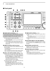
... internal power supply is switched ON. e PANEL LOCK SWITCH [PANEL LOCK] (p. 9-2) ➥ Push to turn the panel lock function ON or OFF. to turn the receiver power ON. • The [POWER] indicator above this switch are connected, the internal speaker or connected external speaker does not function. 1-2 Connects to the AUX...
... internal power supply is switched ON. e PANEL LOCK SWITCH [PANEL LOCK] (p. 9-2) ➥ Push to turn the panel lock function ON or OFF. to turn the receiver power ON. • The [POWER] indicator above this switch are connected, the internal speaker or connected external speaker does not function. 1-2 Connects to the AUX...
Instruction Manual
Page 13
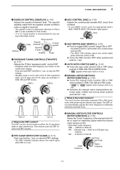
...] control usage ON or OFF. • Use [AGC] control to effectively eliminate unwanted tones. High cut Center Low cut ✔ What is open. This receiver uses the DSP circuit for the PBT function. !0 PBT CLEAR SWITCH [PBT CLEAR] (p. 5-11) Push and hold [PBT CLEAR] for 1 sec. Shallow Deep...are shown on the multifunction display. • Push and hold for 1 sec. The squelch disables output from the speaker (closed condition) when no signal is received. • The squelch control is ON. • Notch filter center frequency: SSB : -1060 Hz to 4040 Hz CW : CW pitch freq. + ...
...] control usage ON or OFF. • Use [AGC] control to effectively eliminate unwanted tones. High cut Center Low cut ✔ What is open. This receiver uses the DSP circuit for the PBT function. !0 PBT CLEAR SWITCH [PBT CLEAR] (p. 5-11) Push and hold [PBT CLEAR] for 1 sec. Shallow Deep...are shown on the multifunction display. • Push and hold for 1 sec. The squelch disables output from the speaker (closed condition) when no signal is received. • The squelch control is ON. • Notch filter center frequency: SSB : -1060 Hz to 4040 Hz CW : CW pitch freq. + ...
Instruction Manual
Page 15
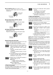
... "P. useful for 1 sec. (p. 5-9) ✔ What is available. • "VR (volume)" indicates that AGC time constant depends on the receiving conditions. ➥ Switches between NAC squelch, selective squelch and OFF in P25 mode. (p. 4-19) ➥ Enters the code set screen when ...attenuator when pushed and held for 1 sec. p. 3-9) Adjusts the treble response of the audio output. p. 3-8) Varies the audio output level of 2 receive RF preamps or bypasses them. (p. 5-9) ● HF bands • "P. Audio output increases Audio output decreases @3 BASS RESPONSE CONTROL [BASS] (outer...
... "P. useful for 1 sec. (p. 5-9) ✔ What is available. • "VR (volume)" indicates that AGC time constant depends on the receiving conditions. ➥ Switches between NAC squelch, selective squelch and OFF in P25 mode. (p. 4-19) ➥ Enters the code set screen when ...attenuator when pushed and held for 1 sec. p. 3-9) Adjusts the treble response of the audio output. p. 3-8) Varies the audio output level of 2 receive RF preamps or bypasses them. (p. 5-9) ● HF bands • "P. Audio output increases Audio output decreases @3 BASS RESPONSE CONTROL [BASS] (outer...
Instruction Manual
Page 16
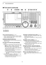
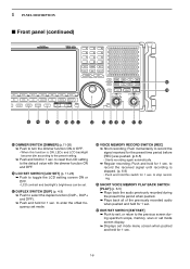
...; Unwanted tuning step for each operating mode can be set between 0.1 and 999.9 kHz in 0.1 kHz steps. ➠ To set mode settings, etc. @7 RECEIVE INDICATOR [RECEIVE] Lights green while receiving a signal and when the squelch is activated. 1-6 1 PANEL DESCRIPTION ■ Front panel (continued) @6 @7 @8 @9 #0 #1 #2 #3 #4 #5 #6 #7 #8 #9 $0 $1 $2 $3 $4 @6 ...ON or OFF when pushed and held for 1 sec. #1 REMOTE CONTROL INDICATOR [REMOTE] Lights yellow when a command is received from a PC via the keypad, then push [YUP] or [ZDOWN]. ➥ Push and hold [▲UP] (or [▼DOWN]) for ...
...; Unwanted tuning step for each operating mode can be set between 0.1 and 999.9 kHz in 0.1 kHz steps. ➠ To set mode settings, etc. @7 RECEIVE INDICATOR [RECEIVE] Lights green while receiving a signal and when the squelch is activated. 1-6 1 PANEL DESCRIPTION ■ Front panel (continued) @6 @7 @8 @9 #0 #1 #2 #3 #4 #5 #6 #7 #8 #9 $0 $1 $2 $3 $4 @6 ...ON or OFF when pushed and held for 1 sec. #1 REMOTE CONTROL INDICATOR [REMOTE] Lights yellow when a command is received from a PC via the keypad, then push [YUP] or [ZDOWN]. ➥ Push and hold [▲UP] (or [▼DOWN]) for ...
Instruction Manual
Page 17
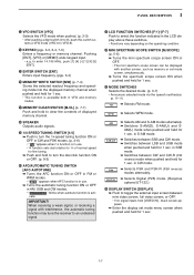
... for 1 sec. 1-7 AM(L) mode when pushed and held for 1 sec. Pushing [ENT], [VFO] or [MEMO] ends keypad input. • e.g. When receiving a weak signal, or receiving a signal with interference, the automatic tuning function may tune the receiver to an undesired signal. $1 LCD FUNCTION SWITCHES [F-1]-[F-7] Push to VFO-9). #4 KEYPAD (pgs. 3-3, 3-4, 7-3) Enters a frequency or memory channel.
... for 1 sec. 1-7 AM(L) mode when pushed and held for 1 sec. Pushing [ENT], [VFO] or [MEMO] ends keypad input. • e.g. When receiving a weak signal, or receiving a signal with interference, the automatic tuning function may tune the receiver to an undesired signal. $1 LCD FUNCTION SWITCHES [F-1]-[F-7] Push to VFO-9). #4 KEYPAD (pgs. 3-3, 3-4, 7-3) Enters a frequency or memory channel.
Instruction Manual
Page 18
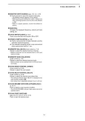
... pushed and held for 1 sec. %0 EXIT/SET SWITCH [EXIT/SET] ➥ Push to exit, or return to record the signal received for the preset time period before [REC] was pushed. (p.6-5) • Starts recording again automatically. ➥ Regular recording; Push and hold... %4 %5 %6 %7 %8 $5 DIMMER SWITCH [DIMMER] (p.11-26) ➥ Push to turn the dimmer function ON or OFF. • When this switch for 1 sec. to record the received signal until recording is stopped. (p. 6-3) • Push and hold this function is ON, LEDs and LCD backlight become dim according to the preset setting. ➥...
... pushed and held for 1 sec. %0 EXIT/SET SWITCH [EXIT/SET] ➥ Push to exit, or return to record the signal received for the preset time period before [REC] was pushed. (p.6-5) • Starts recording again automatically. ➥ Regular recording; Push and hold... %4 %5 %6 %7 %8 $5 DIMMER SWITCH [DIMMER] (p.11-26) ➥ Push to turn the dimmer function ON or OFF. • When this switch for 1 sec. to record the received signal until recording is stopped. (p. 6-3) • Push and hold this function is ON, LEDs and LCD backlight become dim according to the preset setting. ➥...
Instruction Manual
Page 19
... and hold to open the squelch manually. • The [MONI] indicator appears on the display. • While pushing and holding this switch, release any other receiving functions such as the noise blanker or ANF. • While in a duplex operation, monitor the shifted frequency. %2 MAIN DIAL Changes the displayed frequency, selects set...
... and hold to open the squelch manually. • The [MONI] indicator appears on the display. • While pushing and holding this switch, release any other receiving functions such as the noise blanker or ANF. • While in a duplex operation, monitor the shifted frequency. %2 MAIN DIAL Changes the displayed frequency, selects set...
Instruction Manual
Page 20
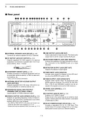
... the others set mode to activate this jack when scan stopped. (p. 11-11) • Output level can be adjusted in parallel with WFM mode are received. The fixed audio output level is ON. !1 VIDEO OUTPUT JACK [VIDEO OUT] Outputs video signals when TV frequencies with 13.8 V outputs of [ACC]. (max. 1 A total...
... the others set mode to activate this jack when scan stopped. (p. 11-11) • Output level can be adjusted in parallel with WFM mode are received. The fixed audio output level is ON. !1 VIDEO OUTPUT JACK [VIDEO OUT] Outputs video signals when TV frequencies with 13.8 V outputs of [ACC]. (max. 1 A total...
Instruction Manual
Page 21
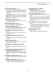
... 2-5) Accepts a 50 Ω antenna with a Type-N connector. Using a fuse rated for a different input power may damege your house electrical system or the receiver. !6 AC POWER SOCKET [AC] (p. 2-5) Connects the supplied AC power cable to an AC line-voltage receptacle. !7 MAIN POWER SWITCH [I/O] (p. 3-2) Turns ... transceive operation with another Icom CI-V transceiver or receiver. @9 DATA SOCKET [DATA IN] (pgs. 2-10, 2-12) Outputs LCD monitor signals (NTSC system). 1-11 Can be used for remote control of the receiver. ➥ Used for external control of the IC-R9500 without the optional CT...
... 2-5) Accepts a 50 Ω antenna with a Type-N connector. Using a fuse rated for a different input power may damege your house electrical system or the receiver. !6 AC POWER SOCKET [AC] (p. 2-5) Connects the supplied AC power cable to an AC line-voltage receptacle. !7 MAIN POWER SWITCH [I/O] (p. 3-2) Turns ... transceive operation with another Icom CI-V transceiver or receiver. @9 DATA SOCKET [DATA IN] (pgs. 2-10, 2-12) Outputs LCD monitor signals (NTSC system). 1-11 Can be used for remote control of the receiver. ➥ Used for external control of the IC-R9500 without the optional CT...
Instruction Manual
Page 22
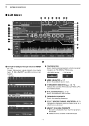
... memory mode. 1-12 1 PANEL DESCRIPTION ■ LCD display q w e r t y u i o @9 @8 @7 @6 @5 @4 @3 @2 @1 @0 !9 !8 !7 !6 !5 !4 !3 !2 !1 !0 q RSSI (Received Signal Strength Indication) METER (p. 3-10) Shows the received signal strength. Four meter types, S, dBµ, dBµ(EMF) and dBm meters are selectable. • S-meter w CENTER METER Shows that the... received signal is set as a select memory channel. r VFO/MEMORY INDICATOR (pgs. 3-3, 7-3) Indicates the selected VFO number (VFO...
... memory mode. 1-12 1 PANEL DESCRIPTION ■ LCD display q w e r t y u i o @9 @8 @7 @6 @5 @4 @3 @2 @1 @0 !9 !8 !7 !6 !5 !4 !3 !2 !1 !0 q RSSI (Received Signal Strength Indication) METER (p. 3-10) Shows the received signal strength. Four meter types, S, dBµ, dBµ(EMF) and dBm meters are selectable. • S-meter w CENTER METER Shows that the... received signal is set as a select memory channel. r VFO/MEMORY INDICATOR (pgs. 3-3, 7-3) Indicates the selected VFO number (VFO...
Instruction Manual
Page 25
... and frequency 2-9 ■ Monitor display connection 2-10 ■ Transceive function 2-10 ■ FSK and AFSK (SSTV) connections 2-11 ■ Accessory connector information 2-12 CAUTION!: The receiver weighs approx. 20 kg (44 lb). Always have two people available to carry, lift or turn over the...
... and frequency 2-9 ■ Monitor display connection 2-10 ■ Transceive function 2-10 ■ FSK and AFSK (SSTV) connections 2-11 ■ Accessory connector information 2-12 CAUTION!: The receiver weighs approx. 20 kg (44 lb). Always have two people available to carry, lift or turn over the...
Instruction Manual
Page 26
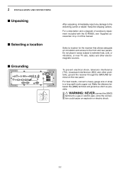
..., cold, or vibrations, or near TV sets, radios and other problems, ground the receiver through the GROUND terminal on p. iii of accessory equipment included with the IC-R9500, see 'Supplied accessories' on the rear panel. Select a location for the receiver that allows adequate air circulation and access to a long earth-sunk copper rod. For...
..., cold, or vibrations, or near TV sets, radios and other problems, ground the receiver through the GROUND terminal on p. iii of accessory equipment included with the IC-R9500, see 'Supplied accessories' on the rear panel. Select a location for the receiver that allows adequate air circulation and access to a long earth-sunk copper rod. For...

