Instruction Manual
Page 1
COMMUNICATIONS RECEIVER iR9500 Instruction Manual A-6553H-1EX-q Printed in Japan © 2007 Icom Inc.
COMMUNICATIONS RECEIVER iR9500 Instruction Manual A-6553H-1EX-q Printed in Japan © 2007 Icom Inc.
Instruction Manual
Page 3
...cohol when cleaning the IC-R9500, as small dark or light spots. AVOID using or storing the receiver in your authority to the receiver. During maritime mobile operation, keep the receiver as far away ...Icom Inc., could void your ears, reduce the volume or discontinue use. P25 digital mode is available when the optional UT-122 DIGITAL UNIT is protected by unauthorized internal adjustment. The receiver... sein. This may have two people available to this communications equipment. AVOID placing the receiver against continuous high volume operation. This is explicitly prohibited from...
...cohol when cleaning the IC-R9500, as small dark or light spots. AVOID using or storing the receiver in your authority to the receiver. During maritime mobile operation, keep the receiver as far away ...Icom Inc., could void your ears, reduce the volume or discontinue use. P25 digital mode is available when the optional UT-122 DIGITAL UNIT is protected by unauthorized internal adjustment. The receiver... sein. This may have two people available to this communications equipment. AVOID placing the receiver against continuous high volume operation. This is explicitly prohibited from...
Instruction Manual
Page 20
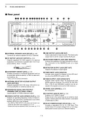
... REMOTE JACK [REC REMOTE] Controls the operation of external equipment such as an automatic antenna selector, a TNC for data communications, etc. • See p. 2-12 for external equipment. The NTSC M, PAL B/G, PAL I /O 10MHz-10dBm] Inputs..., S-meter indication and time with a synthesized voice when pushing [SPCH] or scan stopped. • Turn ON the "REC SPCH" in parallel with WFM mode are received. Connects to 15 V DC input. w DC OUTPUT JACK [DC OUTPUT] (p. 2-6) Outputs regulated 15 V DC (approx.) for socket information. 1 PANEL DESCRIPTION ■ Rear panel q w e r t y ...
... REMOTE JACK [REC REMOTE] Controls the operation of external equipment such as an automatic antenna selector, a TNC for data communications, etc. • See p. 2-12 for external equipment. The NTSC M, PAL B/G, PAL I /O 10MHz-10dBm] Inputs..., S-meter indication and time with a synthesized voice when pushing [SPCH] or scan stopped. • Turn ON the "REC SPCH" in parallel with WFM mode are received. Connects to 15 V DC input. w DC OUTPUT JACK [DC OUTPUT] (p. 2-6) Outputs regulated 15 V DC (approx.) for socket information. 1 PANEL DESCRIPTION ■ Rear panel q w e r t y ...
Instruction Manual
Page 35
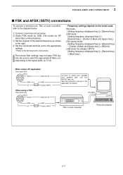
...Rear panel view [ACC] 76 381 54 2 SQLS GND AF SQELCH IN GND AUDIO INPUT Connect to the desired frequency as below . e Set the receiver to serial port, parallel port, speaker jack, and line IN/OUT jack, etc. q Connect a terminal unit as shown to the diagram below ....- [Center of Mark and Space freq.] CW narrow mode: [Setting frequency (displayed freq.)] = [Desired freq.] - [Center of the application for HF band data communications). 2 INSTALLATION AND CONNECTIONS ■ FSK and AFSK (SSTV) connections To connect a terminal unit, TNC or scan converter, refer to the right.
...Rear panel view [ACC] 76 381 54 2 SQLS GND AF SQELCH IN GND AUDIO INPUT Connect to the desired frequency as below . e Set the receiver to serial port, parallel port, speaker jack, and line IN/OUT jack, etc. q Connect a terminal unit as shown to the diagram below ....- [Center of Mark and Space freq.] CW narrow mode: [Setting frequency (displayed freq.)] = [Desired freq.] - [Center of the application for HF band data communications). 2 INSTALLATION AND CONNECTIONS ■ FSK and AFSK (SSTV) connections To connect a terminal unit, TNC or scan converter, refer to the right.
Instruction Manual
Page 49
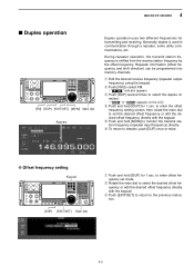
... for 1 sec. Repeater information (offset frequency and shift direction) can be programmed into memory channels. r Push and hold [DUP] for transmitting and receiving. e Push [DUP] several times to simplex, push [DUP] once or twice. " or " DUP+ " appears on the LCD. y To ...return to select the duplex direction. • " DUP- During repeater operation, the transmit station frequency is used in communication through a repeater, some utility communications, etc. w Rotate the main dial to enter offset frequency set the desired offset frequency or edit the desired offset frequency...
... for 1 sec. Repeater information (offset frequency and shift direction) can be programmed into memory channels. r Push and hold [DUP] for transmitting and receiving. e Push [DUP] several times to simplex, push [DUP] once or twice. " or " DUP+ " appears on the LCD. y To ...return to select the duplex direction. • " DUP- During repeater operation, the transmit station frequency is used in communication through a repeater, some utility communications, etc. w Rotate the main dial to enter offset frequency set the desired offset frequency or edit the desired offset frequency...
Instruction Manual
Page 166
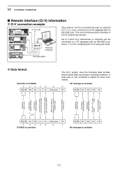
... End of message code (fixed) (fixed) FE FE E0 72H Cn Sc Data area FD q w ert y u IC-R9500 to controller FE FE E0 72H FA FD NG message to controller 13-2 The Icom Communications Interface-V (CI-V) controls the receiver. mini-plug cable D Data format Controller to command numbers. 13 CONTROL COMMAND ■ Remote interface (CI...
... End of message code (fixed) (fixed) FE FE E0 72H Cn Sc Data area FD q w ert y u IC-R9500 to controller FE FE E0 72H FA FD NG message to controller 13-2 The Icom Communications Interface-V (CI-V) controls the receiver. mini-plug cable D Data format Controller to command numbers. 13 CONTROL COMMAND ■ Remote interface (CI...

Instruction Manual
Page 188
... from the PC iR9500 COMMUNICATIONS RECEIVER q Start up the IC-R9500 Firm Utility. • The window as the location. w Read the caution in the window carefully. Click to continue IC-R9500 Firm Utility iR9500 COMMUNICATIONS RECEIVER Firmware File Name Click ...[...] to the firmware download homepage and/or the instruction manual for the correct procedures in such case. r Select the firmware file with the "dat" extension (e.g.: 9500xxxx.dat). • Click [...], then select the file, as well as at Icom...
... from the PC iR9500 COMMUNICATIONS RECEIVER q Start up the IC-R9500 Firm Utility. • The window as the location. w Read the caution in the window carefully. Click to continue IC-R9500 Firm Utility iR9500 COMMUNICATIONS RECEIVER Firmware File Name Click ...[...] to the firmware download homepage and/or the instruction manual for the correct procedures in such case. r Select the firmware file with the "dat" extension (e.g.: 9500xxxx.dat). • Click [...], then select the file, as well as at Icom...

Instruction Manual
Page 189
...IC-R9500 display. Version 1.00 (C) 2006 Icom Inc. After turning the power ON, the IC-R9500 will start automatically depending on the status of the update process, either of dialogs at this stage. The sub CPU and/or DSP firmware update will work with [POWER] switch. The receiver...The "FIRMWARE UPDATING" dialog as above disappears. !1 Push [POWER] to the IC-R9500. 15 UPDATING THE FIRMWARE IC-R9500 Firm Utility iR9500 COMMUNICATIONS RECEIVER Firmware File Name IC-R9500 IP Address Connecting to finish the firmware update. RX-DSP UPDATING... WARNING! ...
...IC-R9500 display. Version 1.00 (C) 2006 Icom Inc. After turning the power ON, the IC-R9500 will start automatically depending on the status of the update process, either of dialogs at this stage. The sub CPU and/or DSP firmware update will work with [POWER] switch. The receiver...The "FIRMWARE UPDATING" dialog as above disappears. !1 Push [POWER] to the IC-R9500. 15 UPDATING THE FIRMWARE IC-R9500 Firm Utility iR9500 COMMUNICATIONS RECEIVER Firmware File Name IC-R9500 IP Address Connecting to finish the firmware update. RX-DSP UPDATING... WARNING! ...
Instruction Manual
Page 190
Kind of equipment: COMMUNICATIONS RECEIVER Type-designation: iR9500 Version (where applicable): This compliance is based on our sole responsibility that this equipment complies with the following harmonised standards, specifications or ... Directive, 1999/5/EC, and that any applicable Essential Test Suite measurements have been performed. Ikegami General Manager Signature iv)v) ABOUT CE DECLARATION OF CONFORMITY We Icom Inc. Japan 1-1-32, Kamiminami, Hirano-ku Osaka 547-0003, Japan Declare on conformity with the essential requirements of issue...
Kind of equipment: COMMUNICATIONS RECEIVER Type-designation: iR9500 Version (where applicable): This compliance is based on our sole responsibility that this equipment complies with the following harmonised standards, specifications or ... Directive, 1999/5/EC, and that any applicable Essential Test Suite measurements have been performed. Ikegami General Manager Signature iv)v) ABOUT CE DECLARATION OF CONFORMITY We Icom Inc. Japan 1-1-32, Kamiminami, Hirano-ku Osaka 547-0003, Japan Declare on conformity with the essential requirements of issue...
Technical Specifications
Page 2
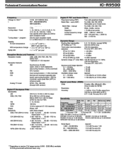
r9500 **Depending on version. Full range version (0.005 - 3335 MHz) available to USA government authorized users only. Professional Communications Receiver Range for USA**: 0.005 - 821.999999 MHz, 851 - 866.999999 MHz, 896-3335 MHz ic-
r9500 **Depending on version. Full range version (0.005 - 3335 MHz) available to USA government authorized users only. Professional Communications Receiver Range for USA**: 0.005 - 821.999999 MHz, 851 - 866.999999 MHz, 896-3335 MHz ic-

Technical Specifications
Page 4
r9500 ©2007 The Icom logo is a registered trademark of Icom Inc. 9772 2380 116th Ave NE Bellevue, WA 98004 Voice: 425-454-8155 Fax: 425-454-1509 www.icomamerica.com Professional Communications Receiver ic-
r9500 ©2007 The Icom logo is a registered trademark of Icom Inc. 9772 2380 116th Ave NE Bellevue, WA 98004 Voice: 425-454-8155 Fax: 425-454-1509 www.icomamerica.com Professional Communications Receiver ic-

Service Manual
Page 2
... could damage the receiver's front end. An insulated tuning tool MUST be used for the IC-R9500 COMMUNICATIONS RECEIVER at the time of test equipment throughly before disassembling the receiver. 2. READ the instructions of publication. DO NOT open the receiver until the receiver is internal before connecting... Turn them slowly and smoothly. 4. DO NOT short any of Icom Incorporated (Japan) in the United States the United Kingdom Germany France Spain Russia and/or other countries. Icom Icom Inc. DO NOT keep power ON for your convenience. CAUTION NEVER...
... could damage the receiver's front end. An insulated tuning tool MUST be used for the IC-R9500 COMMUNICATIONS RECEIVER at the time of test equipment throughly before disassembling the receiver. 2. READ the instructions of publication. DO NOT open the receiver until the receiver is internal before connecting... Turn them slowly and smoothly. 4. DO NOT short any of Icom Incorporated (Japan) in the United States the United Kingdom Germany France Spain Russia and/or other countries. Icom Icom Inc. DO NOT keep power ON for your convenience. CAUTION NEVER...
Service Manual
Page 13
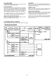
...(IC201, IC202). COMPACT FLASH IC402 is the power controller for work space. IC103 (CPU1) and IC604 (CPU2) communicate each data is routed to the whole of the receiver. • VOLTAGE BLOCK DIAGRAM AC AC-SW AC-DC IN SW VDD15V REG VDD3R3VA REG VDD3R3VB VDD15V SW 15V REG... EEPROM (IC403) stores the settings for storing program, image and audio files. A portion of the IC-R9500, and processes audio signal. LAN DRIVER LAN driver IC (IC404) conduct the LAN communications via the dual port SRAM (IC51). 3-3 LOGIC UNIT LOGIC UNIT generally controls the whole of the circuit of...
...(IC201, IC202). COMPACT FLASH IC402 is the power controller for work space. IC103 (CPU1) and IC604 (CPU2) communicate each data is routed to the whole of the receiver. • VOLTAGE BLOCK DIAGRAM AC AC-SW AC-DC IN SW VDD15V REG VDD3R3VA REG VDD3R3VB VDD15V SW 15V REG... EEPROM (IC403) stores the settings for storing program, image and audio files. A portion of the IC-R9500, and processes audio signal. LAN DRIVER LAN driver IC (IC404) conduct the LAN communications via the dual port SRAM (IC51). 3-3 LOGIC UNIT LOGIC UNIT generally controls the whole of the circuit of...

