
Instruction Manual
Page 12
e r ACCESSORY CONNECTOR [ACC] (pgs. 12, 13, 61) Connects a CW keyer or an FSK terminal unit, etc. e MODEM CONNECTOR [AF/MOD] (pgs. 53, 62) Connects to a PC via an RS232C cable (D-sub 9-pin). t CONTROLLER CONNECTOR [CONTROLLER] (p. 53) Connects the supplied remote controller. w REMOTE CONNECTOR [REMOTE] (pgs. ...
e r ACCESSORY CONNECTOR [ACC] (pgs. 12, 13, 61) Connects a CW keyer or an FSK terminal unit, etc. e MODEM CONNECTOR [AF/MOD] (pgs. 53, 62) Connects to a PC via an RS232C cable (D-sub 9-pin). t CONTROLLER CONNECTOR [CONTROLLER] (p. 53) Connects the supplied remote controller. w REMOTE CONNECTOR [REMOTE] (pgs. ...

Instruction Manual
Page 55
...select the desired e-mail channel. Ask your provider for connection details. e Push [e-mail] then rotate [GRP] and [CH] to [AF/MOD] on the IC-M802 main unit front panel. • See page 53 for e-mail operation in advance. r Follow the e-mail application instruction for simple operation. ...8226; Selectable e-mail frequencies may need to 160 e-mail frequency channels and a connecting terminal for an e-mail modem are available. I General The IC-M802 is ready for more details. NOTE: For e-mail operation, you MUST make a contract with a push of a button or group/channel selector ...
...select the desired e-mail channel. Ask your provider for connection details. e Push [e-mail] then rotate [GRP] and [CH] to [AF/MOD] on the IC-M802 main unit front panel. • See page 53 for e-mail operation in advance. r Follow the e-mail application instruction for simple operation. ...8226; Selectable e-mail frequencies may need to 160 e-mail frequency channels and a connecting terminal for an e-mail modem are available. I General The IC-M802 is ready for more details. NOTE: For e-mail operation, you MUST make a contract with a push of a button or group/channel selector ...

Instruction Manual
Page 60
... selects the input/output terminal for signals to/from an external unit, such as an HF e-mail modem, TNC (Terminal Node Controller), etc. (default: AF/MOD) Position indication type Select the position indicating type from simple and detail. • SIMPLE : Hides second digits (default) • DETAIL : Shows second digits Offset time...
... selects the input/output terminal for signals to/from an external unit, such as an HF e-mail modem, TNC (Terminal Node Controller), etc. (default: AF/MOD) Position indication type Select the position indicating type from simple and detail. • SIMPLE : Hides second digits (default) • DETAIL : Shows second digits Offset time...
Instruction Manual
Page 69
.... * DC GND Common ground. Coaxial ground for AF1 and AF2. Specification Input impedance : 2.4 kΩ When grounded, transmits. When grounded, transmits. * 76 381 54 2 4 MOD Modulator input. Input level Specification : Less than 0.6 V for transmit Ground level Input current : -0.5 to 0.8 V : Less than 20 mA Input impedance : 5 kΩ Input level...
.... * DC GND Common ground. Coaxial ground for AF1 and AF2. Specification Input impedance : 2.4 kΩ When grounded, transmits. When grounded, transmits. * 76 381 54 2 4 MOD Modulator input. Input level Specification : Less than 0.6 V for transmit Ground level Input current : -0.5 to 0.8 V : Less than 20 mA Input impedance : 5 kΩ Input level...
Instruction Manual
Page 70
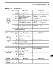
13 CONFECTION AND INSTALLATION I Connector information (continued) AF/MOD 5 1 9 6 Pin Pin name Description 1 MOD+ Modulation input from an external terminal unit. 2 MOD- Coaxial ground for NAF+. 6 GND Ground for digital equipment. 7 NC No connection. 8 SEND Transmits when grounded. 9 GND Ground for clear-to-send data. 9 NC No ...
13 CONFECTION AND INSTALLATION I Connector information (continued) AF/MOD 5 1 9 6 Pin Pin name Description 1 MOD+ Modulation input from an external terminal unit. 2 MOD- Coaxial ground for NAF+. 6 GND Ground for digital equipment. 7 NC No connection. 8 SEND Transmits when grounded. 9 GND Ground for clear-to-send data. 9 NC No ...
Instruction Manual
Page 74
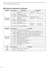
... • CONTROLLER connector : 8-pin MINI DIN connector • GPS connector : BNC connector (NMEA0183 ver. 3.01) • REMOTE connector : D-sub 9-pin (RS-232C/NMEA) • AF/MOD connector : D-sub 9-pin • Transmitter • Output power 1.6-27.5000 MHz • Spurious emission • Carrier suppression • Unwanted sideband suppression • Mic. range : -30...
... • CONTROLLER connector : 8-pin MINI DIN connector • GPS connector : BNC connector (NMEA0183 ver. 3.01) • REMOTE connector : D-sub 9-pin (RS-232C/NMEA) • AF/MOD connector : D-sub 9-pin • Transmitter • Output power 1.6-27.5000 MHz • Spurious emission • Carrier suppression • Unwanted sideband suppression • Mic. range : -30...


