Icom IC-FR6300 Support and Manuals
Get Help and Manuals for this Icom item
View All Support Options Below
Free Icom IC-FR6300 manuals!
Problems with Icom IC-FR6300?
Ask a Question
Free Icom IC-FR6300 manuals!
Problems with Icom IC-FR6300?
Ask a Question
Popular Icom IC-FR6300 Manual Pages
Instruction Manual - Page 1
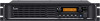
INSTRUCTION MANUAL
VHF DIGITAL REPEATER
|FR5300
UHF DIGITAL REPEATER
|FR6300
Instruction Manual - Page 2
..., lightning, other countries.
No risk of trouble-free operation. m O nline control and Digital Trunking operation
Online control and digital trunking operation are built-in as standard.
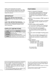
With proper care, this product should provide you for the IC-FR5300/IC-FR6300 vhf/uhf digital repeaters. IMPORTANT
READ THIS INSTRUCTION MANUAL CAREFULLY before attempting to 2 channels of the...
Instruction Manual - Page 3
... or make incorrect contact with wet hands.
ii NEVER install the antenna at any liquids.
Contact your Icom dealer or distributor for extended periods.
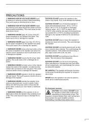
CAUTION: DO NOT ...damage to avoid use or leave the repeater in excessively dusty environments. CAUTION: DO NOT use non-Icom microphones. For European versions CAUTION: Hot surfaces.
R WARNING! R WARNING! R WARNING! NEVER ...
Instruction Manual - Page 4
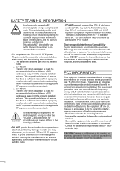
...installed externally-mounted antenna to do so. Transmitting more than 50% of total radio use with the instructions, may also cause you to radio communications.
Electromagnetic Interference/Compatibility During transmissions, your Icom... in the applicable RF exposure compliance standards.
2. IC-FR6300: Transmit only when people are designed to electromagnetic radiation...
Instruction Manual - Page 7
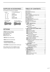
...8226; UR-FR5300/UR-FR6300 channel extension modules
• UC-FR5300 trunking/network controller
Some options may not be available in some countries. INSTALLATION AND CONNECTIONS 4 ■...install. MAINTENANCE 9 ■■Troubleshooting 9
5. INFORMATION 10 ■■About CE and DOC 10 ■■Disposal 10 ■■Voice coding technology 10 ■■Installation...
Instruction Manual - Page 9
... optional trunking/network controller
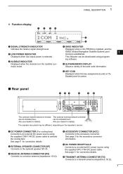
can be installed here. The repeater rear panel may be installed here. See page 5 for details. 1 PANEL DESCRIPTION
DD Function display
q w er
ICOM Inc.
e RECEIVE ANTENNA CONNECTOR ...software. t ALPHANUMERIC DISPLAY Shows a variety of text and code information. mute) mode.
e AUDIBLE INDICATOR Displayed when the channel is selected.
t ...
Instruction Manual - Page 10
...- - -
-
- - - -
-
-
-
- -
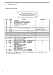
*1 A desired function can be assigned.*1 (Default: Null)
Specification
Input level: 85 mV rms
Output level: 300 mV rms
- Output terminal for AF signals from an external terminal unit. Output ...level is fixed, regardless of the [AF] control setting. D/A
VCC NC NC GND EXT.I/O 15
EXT.I/O 16
EXT.I/O 17 EXT.I/O 18 EXT.I/O...
Instruction Manual - Page 11
... the screws.
14
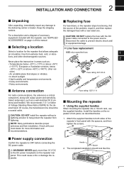
antennas and their installation. Of course, the transmission line should look like this manual.
Check with the DC
power cable connected...Replacing fuse
If a fuse blows, or the repeater stops functioning, find the source of this .
19
to help protect the repeater from extreme heat, cold, or vibra- Install the handles on page vi of the problem, repair it, and then replace...
Instruction Manual - Page 12
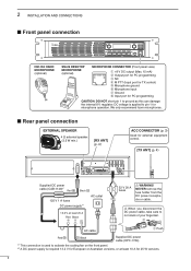
2 INSTALLATION AND CONNECTIONS ■■Front panel connection
P0
P1
P2
P3
P4
HM-152 HAND... to ground as this can damage the internal 8 V regulator. NEVER remove the fuse holder from the DC power receptacle or cable. We only recommend Icom microphones.
■■Rear panel connection
EXTERNAL SPEAKER
4 ø external speaker. (3.5 W min.)
[RX ANT] (p. 4)
ACC CONNECTOR (p. 3) ...
Instruction Manual - Page 13
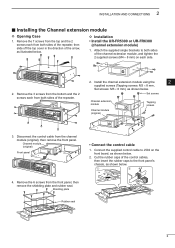
... Installation • Install the UR-FR5300 or UR-FR6300
(channel extension module)
1. Attach the supplied single brackets to both sides of the arrow, as illustrated below .
13
q
w
14
J502
15
16
17
18
19
20
21
6 Shielding plate
Rubber seal
1
2. Install the channel extension module using the
2
supplied screws (Tapping screws: M3 × 8 mm,
Set...
Instruction Manual - Page 15
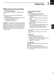
..., then speak at your normal voice level.
12
13
14
15
16
17
18
19
20
21
8 Release [PTT] to adjust the audio output
level. Set the audio and squelch levels. IMPORTANT:
9
To maximize the audio quality of [VOLUME] to turn ON the power. tings. zzRotate [VOLUME] to receive. A protector...
Instruction Manual - Page 16
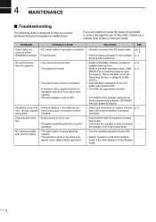
...Icom Dealer or Service Center. are audible.
with a rated one.
If you correct problems that are not equipment malfunctions.
circuited.
• Check and reconnect (or replace if neces- Output power is too • Output power is set to the Full-
• Set... squelch function ON.
-
4 MAINTENANCE
■■Troubleshooting
The following chart is designed to help you are...
Instruction Manual - Page 17
...IC-FR5300 and IC-FR6300
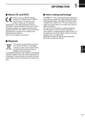
this product is protected by intellectual property rights
which have the "CE" symbol on
3
your
7
area.
8
9
10
11
12
13
14
15
16
17
18
19
20
21
10 https://www.icomjapan.com/support... 5 INFORMATION
■■About CE and DOC
■■Voice coding technology
Hereby, Icom Inc.
The full text of their working life.
requirements of the Radio...
Instruction Manual - Page 19
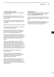
...the roof of an office.
The specification of the RG-213 cable gives a loss
of access
control fence or barrier around the antenna
15
installation should be such that the antenna... distance of
approx. 1.5 m and a height clearance of 3 m.
5
The antenna installation needs to ensure that the
6
lowest part of the antenna is at least 3 m above comments on the mean power averaged over...
Instruction Manual - Page 21
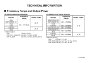
TECHNICAL INFORMATION
■ Frequency Range and Output Power
• IC-FR5300 VHF Digital Repeater
Version
Frequency Range
Output Power
USA
EXP-01/EXP-03 CAN AUS
136 -...6.25 kHz, 12.5 kHz, 25 kHz
EXP-02, EUR:
6.25 kHz, 12.5 kHz, 20 kHz, 25 kHz
• IC-FR6300 UHF Digital Repeater
Version
Frequency Range
Output Power
USA-01/USA-04
EXP-01/EXP-06 400 - 470 MHz
CAN
EXP-03
330 -...
Icom IC-FR6300 Reviews
We have not received any reviews for Icom yet.