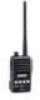
Mdc 1200 Compatible Models
Page 1
... trademarks are not included; WxHxD) Weight (approx.) RF output power (VHF/UHF) LCD display PTT ID Alias Table Selcall Call Alert Status Message Status Request Message Emergency Lone Worker function Radio Check Radio Stun/Revive Call log External out Number of channels Dimensions (projections are not included; UT-124) IC-F5021 IC-F5023/H IC-F6021 IC-F6023/H 136−174MHz 400−470MHz 450−...
... trademarks are not included; WxHxD) Weight (approx.) RF output power (VHF/UHF) LCD display PTT ID Alias Table Selcall Call Alert Status Message Status Request Message Emergency Lone Worker function Radio Check Radio Stun/Revive Call log External out Number of channels Dimensions (projections are not included; UT-124) IC-F5021 IC-F5023/H IC-F6021 IC-F6023/H 136−174MHz 400−470MHz 450−...
Mdc 1200 Compatible Models
Page 2
... Output* Multiple MDC System Profiles* Compatible with other users by name as to other units to automatically initiate any time. Improves channel efficiency allowing the user to verify if a radio is not pushed, the radio automatically transmits an emergency signal. Allows the dispatch to send commonly used in the field without disturbing other users. Perfect for special modifications when radio receives a select call, call alert...
... Output* Multiple MDC System Profiles* Compatible with other users by name as to other units to automatically initiate any time. Improves channel efficiency allowing the user to verify if a radio is not pushed, the radio automatically transmits an emergency signal. Allows the dispatch to send commonly used in the field without disturbing other users. Perfect for special modifications when radio receives a select call, call alert...
Instruction Manual
Page 3
..." lights red. You can cause FCC RF exposure compliance requirements to electromagnetic radiation such as hospitals, aircraft, and blasting sites. Occupational/Controlled Use The radio transmitter is the antenna supplied with this radio operates with other devices or systems. To avoid such interference, turn off to do to assure that this radio. • DO NOT transmit for more than 50% of the time...
..." lights red. You can cause FCC RF exposure compliance requirements to electromagnetic radiation such as hospitals, aircraft, and blasting sites. Occupational/Controlled Use The radio transmitter is the antenna supplied with this radio operates with other devices or systems. To avoid such interference, turn off to do to assure that this radio. • DO NOT transmit for more than 50% of the time...
Instruction Manual
Page 4
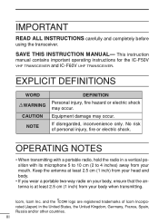
... least 2.5 cm (1 inch) from your body when transmitting. This instruction manual contains important operating instructions for the IC-F50V VHF TRANSCEIVER and IC-F60V UHF TRANSCEIVER. IMPORTANT READ ALL INSTRUCTIONS carefully and completely before using the transceiver. EXPLICIT DEFINITIONS WORD RWARNING CAUTION NOTE DEFINITION Personal injury, fire hazard or electric shock may occur. rated (Japan) in a vertical position with its microphone 5 to 10 cm (2 to 4 inches) away...
... least 2.5 cm (1 inch) from your body when transmitting. This instruction manual contains important operating instructions for the IC-F50V VHF TRANSCEIVER and IC-F60V UHF TRANSCEIVER. IMPORTANT READ ALL INSTRUCTIONS carefully and completely before using the transceiver. EXPLICIT DEFINITIONS WORD RWARNING CAUTION NOTE DEFINITION Personal injury, fire hazard or electric shock may occur. rated (Japan) in a vertical position with its microphone 5 to 10 cm (2 to 4 inches) away...
Instruction Manual
Page 5
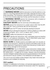
... be guaranteed due to water will ruin the transceiver. MAKE SURE the flexible antenna and battery pack are securely at high volume levels. The IC-F50V/F60V series transceivers employ water- NEVER hold the transceiver so that the antenna is vertical. DO NOT operate the transceiver near unshielded electrical blasting caps or in areas with a headset or other than the BP- 226 or BP...
... be guaranteed due to water will ruin the transceiver. MAKE SURE the flexible antenna and battery pack are securely at high volume levels. The IC-F50V/F60V series transceivers employ water- NEVER hold the transceiver so that the antenna is vertical. DO NOT operate the transceiver near unshielded electrical blasting caps or in areas with a headset or other than the BP- 226 or BP...
Instruction Manual
Page 6
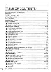
... 4 ' Function display 6 ' Programmable function keys 8 3 BASIC OPERATION 14-23 ' Turning power ON 14 ' Channel selection 14 ' Call procedure 15 ' Receiving and transmitting 16 ' User set mode 20 ' Emergency transmission 21 ' Scrambler function 21 ' Stun function 21 ' Recording function (Depends on the version 22 4 BATTERY CHARGING 24-31 ' Caution 24 ' Optional battery chargers 27 5 BATTERY CASE 32-33 ' Optional battery case (BP-226 32 6 SPEAKER-MICROPHONE 34-35...
... 4 ' Function display 6 ' Programmable function keys 8 3 BASIC OPERATION 14-23 ' Turning power ON 14 ' Channel selection 14 ' Call procedure 15 ' Receiving and transmitting 16 ' User set mode 20 ' Emergency transmission 21 ' Scrambler function 21 ' Stun function 21 ' Recording function (Depends on the version 22 4 BATTERY CHARGING 24-31 ' Caution 24 ' Optional battery chargers 27 5 BATTERY CASE 32-33 ' Optional battery case (BP-226 32 6 SPEAKER-MICROPHONE 34-35...

Instruction Manual
Page 11
... SPEAKER-MICROPHONE JACK [SP MIC] 2 Connects the optional speaker-microphone, etc. [SP MIC] jack cover NOTE: KEEP the [SP MIC] jack cover attached to the transceiver when the optional equipment is not used. (See p. 3 for details) t DEALER-PROGRAMMABLE KEYS [P0] to [P3] The desired functions can be assigned independently by your dealer. (p. 8) u TRANSMIT/BUSY INDICATOR Lights red while transmitting; lights green while receiving a signal, or when the squelch...
... SPEAKER-MICROPHONE JACK [SP MIC] 2 Connects the optional speaker-microphone, etc. [SP MIC] jack cover NOTE: KEEP the [SP MIC] jack cover attached to the transceiver when the optional equipment is not used. (See p. 3 for details) t DEALER-PROGRAMMABLE KEYS [P0] to [P3] The desired functions can be assigned independently by your dealer. (p. 8) u TRANSMIT/BUSY INDICATOR Lights red while transmitting; lights green while receiving a signal, or when the squelch...

Instruction Manual
Page 13
o ALPHANUMERIC DISPLAY Displays an operating channel number, channel names, Set mode contents, DTMF code, etc. *1 BIIS operation only *2 MDC operation only 7 2 PANEL DESCRIPTION i BATTERY INDICATOR 2 Appears or blinks when the battery power decreases to a speci- fied level.
o ALPHANUMERIC DISPLAY Displays an operating channel number, channel names, Set mode contents, DTMF code, etc. *1 BIIS operation only *2 MDC operation only 7 2 PANEL DESCRIPTION i BATTERY INDICATOR 2 Appears or blinks when the battery power decreases to a speci- fied level.
Instruction Manual
Page 14
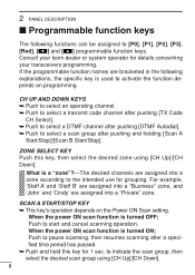
...;c key is used to activate the function depends on the Power ON Scan setting. When the power ON scan function is turned OFF; Push to pause scanning, then resumes scanning after pushing and holding [Scan A Start/Stop]/[Scan B Start/Stop]. SCAN A START/STOP KEY ➥ This key's operation depends on programming. CH UP AND DOWN KEYS ➥ Push to select an operating channel. ➥ Push to select a transmit code channel after pushing...
...;c key is used to activate the function depends on the Power ON Scan setting. When the power ON scan function is turned OFF; Push to pause scanning, then resumes scanning after pushing and holding [Scan A Start/Stop]/[Scan B Start/Stop]. SCAN A START/STOP KEY ➥ This key's operation depends on programming. CH UP AND DOWN KEYS ➥ Push to select an operating channel. ➥ Push to select a transmit code channel after pushing...

Instruction Manual
Page 15
.... 1. Push and hold this key while scan is paused (a signal is detected) on the setting, the cleared channel is added to set the operating channel as the Priority A or Priority B channel. Depending on a channel (except for 1 sec. to select the desired group. 2. Scan resumes after the scan is activated: [PTT], [Light], [Lone Worker], [Surveillance], [Call] (incl. LOCK KEY Push and hold to toggle...
.... 1. Push and hold this key while scan is paused (a signal is detected) on the setting, the cleared channel is added to set the operating channel as the Priority A or Priority B channel. Depending on a channel (except for 1 sec. to select the desired group. 2. Scan resumes after the scan is activated: [PTT], [Light], [Lone Worker], [Surveillance], [Call] (incl. LOCK KEY Push and hold to toggle...

Instruction Manual
Page 16
... as the continuous tone channel until another channel is turned OFF in user set as such. 10 LONE WORKER KEY Push to select the transmit output power temporarily or permanently, depending on each selection. tomatically turned ON after the communication is finished to send a 'reset code'. (BIIS operation only) NOTE: The un-mute condition ('Audible' condition) may automatically return to change the tone frequency/code setting. LIGHT KEY Push to...
... as the continuous tone channel until another channel is turned OFF in user set as such. 10 LONE WORKER KEY Push to select the transmit output power temporarily or permanently, depending on each selection. tomatically turned ON after the communication is finished to send a 'reset code'. (BIIS operation only) NOTE: The un-mute condition ('Audible' condition) may automatically return to change the tone frequency/code setting. LIGHT KEY Push to...

Instruction Manual
Page 17
... the DTMF channel selection mode. Then select the desired DTMF channel using the CS-F50V CLONING SOFTWARE. (PMR operation only) Ask your signalling system. • [Call A] and/or [Call B] may be selected from 25.0 or 20.0 kHz using [CH Up]/[CH Down]. ➥ After selecting the DTMF channel, push again to transmit the se- CALL KEYS Push to transmit a 2/5-tone/BIIS ID code. •...
... the DTMF channel selection mode. Then select the desired DTMF channel using the CS-F50V CLONING SOFTWARE. (PMR operation only) Ask your signalling system. • [Call A] and/or [Call B] may be selected from 25.0 or 20.0 kHz using [CH Up]/[CH Down]. ➥ After selecting the DTMF channel, push again to transmit the se- CALL KEYS Push to transmit a 2/5-tone/BIIS ID code. •...
Instruction Manual
Page 18
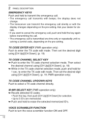
TX CODE ENTER KEY (PMR operation only) Push to select a TX code channel directly. the display does not change. • The transceiver can transmit the emergency call is transmitted one time only or repeatedly until receiving a control code, depending on the pre-setting. Ask your dealer for details. • If you want to cancel the emergency call, push and hold the key again before transmitting the...
TX CODE ENTER KEY (PMR operation only) Push to select a TX code channel directly. the display does not change. • The transceiver can transmit the emergency call is transmitted one time only or repeatedly until receiving a control code, depending on the pre-setting. Ask your dealer for details. • If you want to cancel the emergency call, push and hold the key again before transmitting the...
Instruction Manual
Page 20
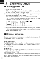
... SCAN TYPE: Channel setting is programmed for a start over in this type. Therefore "01234" and "56789" are available. When turning the power ON, the transceiver automatically starts scanning. Turn the power off and start up . KEY or NUMBER 0 5 1 6 2 7 3 8 4 9 e When the "PASSWORD" indication does not clear after inputting 4 digits, the input code number may differ according to your dealer. • The keys in sequence; Scanning stops when receiving...
... SCAN TYPE: Channel setting is programmed for a start over in this type. Therefore "01234" and "56789" are available. When turning the power ON, the transceiver automatically starts scanning. Turn the power off and start up . KEY or NUMBER 0 5 1 6 2 7 3 8 4 9 e When the "PASSWORD" indication does not clear after inputting 4 digits, the input code number may differ according to your dealer. • The keys in sequence; Scanning stops when receiving...

Instruction Manual
Page 22
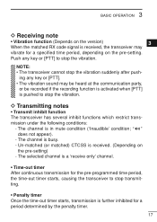
... voice level. • When a tone signalling system is used, the call , adjust the audio output level to 4 inches) from your signal; 1. Transmitting: Wait for antenna attachment. q While pushing and holding [PTT], speak into the microphone at the previous page may damage the transceiver. 3 BASIC OPERATION I Receiving and transmitting NOTE: Transmitting without an antenna may be necessary. Receiving: q Rotate [VOL] to avoid interference. e When receiving a call procedure de- Pause...
... voice level. • When a tone signalling system is used, the call , adjust the audio output level to 4 inches) from your signal; 1. Transmitting: Wait for antenna attachment. q While pushing and holding [PTT], speak into the microphone at the previous page may damage the transceiver. 3 BASIC OPERATION I Receiving and transmitting NOTE: Transmitting without an antenna may be necessary. Receiving: q Rotate [VOL] to avoid interference. e When receiving a call procedure de- Pause...
Instruction Manual
Page 23
... for a period determined by the penalty timer. 17 Un-matched (or matched) CTCSS is busy. - The channel is in mute condition ('Inaudible' condition; " " does not appear). - NOTE: • The transceiver cannot stop the vibration. Push any key or [PTT]. • The vibration sound may vibrate for the pre-programmed time period, the time-out timer starts, causing the transceiver to stop the vibration.
... for a period determined by the penalty timer. 17 Un-matched (or matched) CTCSS is busy. - The channel is in mute condition ('Inaudible' condition; " " does not appear). - NOTE: • The transceiver cannot stop the vibration. Push any key or [PTT]. • The vibration sound may vibrate for the pre-programmed time period, the time-out timer starts, causing the transceiver to stop the vibration.
Instruction Manual
Page 24
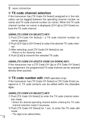
... code channel selec- USING [TX CODE CH SELECT] KEY: q Push [TX Code CH Select]- USING [TX CODE CH UP]/[TX CODE CH DOWN] KEY: If the transceiver has a [TX Code CH Up] or [TX Code CH Down] key assignment, the programmed TX code channel can be edited blinks. 18 to enter the TX code edit mode. • The digit to be selected directly when pushed. D TX code number edit (PMR operation...
... code channel selec- USING [TX CODE CH SELECT] KEY: q Push [TX Code CH Select]- USING [TX CODE CH UP]/[TX CODE CH DOWN] KEY: If the transceiver has a [TX Code CH Up] or [TX Code CH Down] key assignment, the programmed TX code channel can be edited blinks. 18 to enter the TX code edit mode. • The digit to be selected directly when pushed. D TX code number edit (PMR operation...
Instruction Manual
Page 26
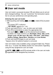
... set mode. * Appears when the optional headset is connected. r Push and hold [P0] for user set mode. w Push and hold [P0] again to enter user set mode functions are Backlight, Beep, SQL Level, Ringer Level, AF Min level, Mic Gain, VOX Gain*, VOX Delay*, Battery Voltage, Signal Moni, Vibration and Lone Worker. User set mode is accessed at power ON and allows you to power ON. • Turn power OFF in the user set mode...
... set mode. * Appears when the optional headset is connected. r Push and hold [P0] for user set mode. w Push and hold [P0] again to enter user set mode functions are Backlight, Beep, SQL Level, Ringer Level, AF Min level, Mic Gain, VOX Gain*, VOX Delay*, Battery Voltage, Signal Moni, Vibration and Lone Worker. User set mode is accessed at power ON and allows you to power ON. • Turn power OFF in the user set mode...
Instruction Manual
Page 30
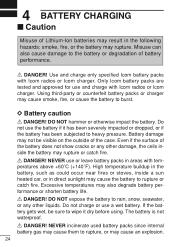
... charge with Icom radios or Icom charger. NEVER incinerate used battery packs since internal battery gas may cause them to rupture, or may also degrade battery performance or shorten battery life. Only Icom battery packs are tested and approved for use the battery if it dry before using. Excessive temperatures may cause an explosion. 24 Do not charge or use or leave battery packs in areas with Icom radios or Icom charger. R DANGER! 4 BATTERY CHARGING...
... charge with Icom radios or Icom charger. NEVER incinerate used battery packs since internal battery gas may cause them to rupture, or may also degrade battery performance or shorten battery life. Only Icom battery packs are tested and approved for use the battery if it dry before using. Excessive temperatures may cause an explosion. 24 Do not charge or use or leave battery packs in areas with Icom radios or Icom charger. R DANGER! 4 BATTERY CHARGING...
Instruction Manual
Page 31
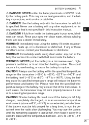
Use the battery only with the transceiver for which it 3 is discolored or deformed. CAUTION! Immediately stop using clean water, any part of its operating temperature range. 17 CAUTION! Immediately wash, using the battery if it must be de- 19 tached from inside the battery. tery...range of the battery may exceed that is out 16 of time. You may not work properly because it safely in this instruction manual. 4 R DANGER! tery may cause heat generation, and the bat- Rinse your Icom dealer or distributor. 8 WARNING! If the battery must be left fully charged...
Use the battery only with the transceiver for which it 3 is discolored or deformed. CAUTION! Immediately stop using clean water, any part of its operating temperature range. 17 CAUTION! Immediately wash, using the battery if it must be de- 19 tached from inside the battery. tery...range of the battery may exceed that is out 16 of time. You may not work properly because it safely in this instruction manual. 4 R DANGER! tery may cause heat generation, and the bat- Rinse your Icom dealer or distributor. 8 WARNING! If the battery must be left fully charged...

