
Instruction Manual
Page 2
... may occur. struction manual contains important operating instructions for optimum use. With proper care, this fine Icom product. NOTE Recommended for the IC-92AD. Text message and call sign exchange - Transmitting position data with the new digital D-STAR technologies for making your IC-92AD your IC-92AD, following Icom's philosophy of your time to thank you for a balanced...
... may occur. struction manual contains important operating instructions for optimum use. With proper care, this fine Icom product. NOTE Recommended for the IC-92AD. Text message and call sign exchange - Transmitting position data with the new digital D-STAR technologies for making your IC-92AD your IC-92AD, following Icom's philosophy of your time to thank you for a balanced...
Instruction Manual
Page 3
...4 mit. 5 BE CAREFUL! Hearing experts advise against continuous high volume operation. anything less may result in a secure place to avoid inadvertent use by Icom Inc., could void your authority to operate this device. This will perform best if the microphone is 5 to 10 cm (2 to 4 ... transceiver. 1 2 DO NOT operate the transceiver near unshielded electri- Safe driving requires your ears, reduce the volume level or discontinue use of more than 16 V DC. PRECAUTIONS RWARNING RF EXPOSURE! Caution should be observed when operating this device under FCC regulations. 15 16...
...4 mit. 5 BE CAREFUL! Hearing experts advise against continuous high volume operation. anything less may result in a secure place to avoid inadvertent use by Icom Inc., could void your authority to operate this device. This will perform best if the microphone is 5 to 10 cm (2 to 4 ... transceiver. 1 2 DO NOT operate the transceiver near unshielded electri- Safe driving requires your ears, reduce the volume level or discontinue use of more than 16 V DC. PRECAUTIONS RWARNING RF EXPOSURE! Caution should be observed when operating this device under FCC regulations. 15 16...
Instruction Manual
Page 4
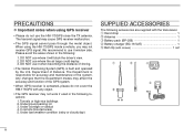
...w e r t iii Underground parking lot 3. Under bad weather condition (rainy or cloudy day) SUPPLIED ACCESSORIES The following locations: 1. DO NOT use where the air bags could deploy. 3. Department of the system. The Department is built and operated by the U.S. Tunnels or high-rise buildings ... • The Global Positioning System (GPS) is responsible for accuracy and maintenance of Defence. Under a bridge or viaduct 4. When using GPS receiver • Please do not cover the HM-175GPS with any object. • The GPS receiver may cause GPS receiver malfunction...
...w e r t iii Underground parking lot 3. Under bad weather condition (rainy or cloudy day) SUPPLIED ACCESSORIES The following locations: 1. DO NOT use where the air bags could deploy. 3. Department of the system. The Department is built and operated by the U.S. Tunnels or high-rise buildings ... • The Global Positioning System (GPS) is responsible for accuracy and maintenance of Defence. Under a bridge or viaduct 4. When using GPS receiver • Please do not cover the HM-175GPS with any object. • The GPS receiver may cause GPS receiver malfunction...
Instruction Manual
Page 5
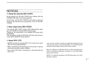
... the OPC-1797. 1 2 3 4 5 6 7 8 9 10 11 12 13 Icom, Icom Inc. D About OPC-1797 • NEVER connect the optional OPC-1797 CONNECTION CABLE with the IC-92AD's AM radio or HF band reception. NOTICES D Using the optional HM-175GPS Noise signals from HM-175GPS The optional HM-175GPS outputs... GPS data (position data, etc.) to IC-92AD at intervals while receiving only. In this case,...
... the OPC-1797. 1 2 3 4 5 6 7 8 9 10 11 12 13 Icom, Icom Inc. D About OPC-1797 • NEVER connect the optional OPC-1797 CONNECTION CABLE with the IC-92AD's AM radio or HF band reception. NOTICES D Using the optional HM-175GPS Noise signals from HM-175GPS The optional HM-175GPS outputs... GPS data (position data, etc.) to IC-92AD at intervals while receiving only. In this case,...
Instruction Manual
Page 9
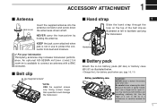
... into the antenna connector and screw down the antenna as illustrated at left to facilitate carrying the transceiver. Because the latch is tightly locked, don't use w something relatively flat, like the edge of a coin or the tip of the belt clip as shown at left . Handstrap ■ Battery ...the Li-Ion battery pack (BP-256) or battery case (BP-257) as illustrated below. • Charge the Li-Ion battery pack before use to protect the connector from dust and moisture. ✔ For your information Third-party antennas may injure yourself. KEEP the jack cover attached when ...
... into the antenna connector and screw down the antenna as illustrated at left to facilitate carrying the transceiver. Because the latch is tightly locked, don't use w something relatively flat, like the edge of a coin or the tip of the belt clip as shown at left . Handstrap ■ Battery ...the Li-Ion battery pack (BP-256) or battery case (BP-257) as illustrated below. • Charge the Li-Ion battery pack before use to protect the connector from dust and moisture. ✔ For your information Third-party antennas may injure yourself. KEEP the jack cover attached when ...
Instruction Manual
Page 14
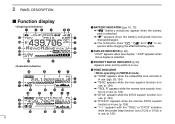
... PRIO EM µ 000 u !0 !3 !2 !1 !4 !8 6 q BATTERY INDICATOR (pgs. 10, 12) ➥ " " (battery indicators) appear when the battery pack is in use. e PRIORITY WATCH INDICATOR (p. 90) Appears when priority watch is attached. ➥ " " appears when the battery cells/pack must be changed/charged. ➥ The indicators show...appears while the reverse tone squelch function is in use. (p. 124) ➥ "DTCS" appears while the DTCS squelch function is in use. (p. 124) ➥ "DTCS R" appears while the reverse DTCS squelch function is in use . (p. 124) ➥ "S" appears with the...
... PRIO EM µ 000 u !0 !3 !2 !1 !4 !8 6 q BATTERY INDICATOR (pgs. 10, 12) ➥ " " (battery indicators) appear when the battery pack is in use. e PRIORITY WATCH INDICATOR (p. 90) Appears when priority watch is attached. ➥ " " appears when the battery cells/pack must be changed/charged. ➥ The indicators show...appears while the reverse tone squelch function is in use. (p. 124) ➥ "DTCS" appears while the DTCS squelch function is in use. (p. 124) ➥ "DTCS R" appears while the reverse DTCS squelch function is in use . (p. 124) ➥ "S" appears with the...

Instruction Manual
Page 15
...Appears "EMR" when the EMR mode operation is selected. (p. 56) ➥ Appears "BK" when the break-in use. (p. 125) t KEY LOCK INDICATOR (pgs. 25, 127) Appears when the key lock function is in use . !3 POWER INDICATOR (p. 24) ➥ "LOW" appears when low power is selected. ➥ "SLO" ...contents, memory names. • The decimal point blinks during scan. y AUTO POWER OFF INDICATOR (p. 96) Appears when the auto power OFF function is in use . o SKIP INDICATOR (pgs. 87, 88) ➥ "SKIP" appears when the selected memory channel is set as a skip frequency. !0 MEMORY CHANNEL NUMBER...
...Appears "EMR" when the EMR mode operation is selected. (p. 56) ➥ Appears "BK" when the break-in use. (p. 125) t KEY LOCK INDICATOR (pgs. 25, 127) Appears when the key lock function is in use . !3 POWER INDICATOR (p. 24) ➥ "LOW" appears when low power is selected. ➥ "SLO" ...contents, memory names. • The decimal point blinks during scan. y AUTO POWER OFF INDICATOR (p. 96) Appears when the auto power OFF function is in use . o SKIP INDICATOR (pgs. 87, 88) ➥ "SKIP" appears when the selected memory channel is set as a skip frequency. !0 MEMORY CHANNEL NUMBER...
Instruction Manual
Page 16
...the battery terminals, or NEVER modify the battery pack. NEVER use with Icom radios. Do not charge or use the battery if it to rupture or catch fire. Immediately wash, using clean water, any other liquids. Rinse your Icom dealer or distributor. • WARNING! Misuse can result. ...D Battery caution • R DANGER! Use and charge only specified Icom battery packs with Icom radios. DO NOT expose the battery ...
...the battery terminals, or NEVER modify the battery pack. NEVER use with Icom radios. Do not charge or use the battery if it to rupture or catch fire. Immediately wash, using clean water, any other liquids. Rinse your Icom dealer or distributor. • WARNING! Misuse can result. ...D Battery caution • R DANGER! Use and charge only specified Icom battery packs with Icom radios. DO NOT expose the battery ...
Instruction Manual
Page 17
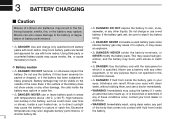
...specified temperature range will activate, causing the battery to the transceiver) into the charger if it is not waterproof. • CAUTION! Using the battery out of the specified temperature range. Continuing to +104˚F). Shorter battery life could occur if the battery is not ...must be reduced. 9 DO NOT charge or leave the battery in an induction heating cooker. Icom recommends charging the battery at +25˚C (+77˚F). Additionally, battery performance or battery life may use the battery within three months). -20˚C (-4˚F) to +140˚F). You may...
...specified temperature range will activate, causing the battery to the transceiver) into the charger if it is not waterproof. • CAUTION! Using the battery out of the specified temperature range. Continuing to +104˚F). Shorter battery life could occur if the battery is not ...must be reduced. 9 DO NOT charge or leave the battery in an induction heating cooker. Icom recommends charging the battery at +25˚C (+77˚F). Additionally, battery performance or battery life may use the battery within three months). -20˚C (-4˚F) to +140˚F). You may...
Instruction Manual
Page 18
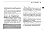
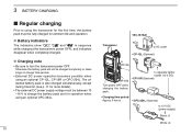
... details) • The external DC power supply voltage must be fully charged for operation when using an optional CP-12L, CP-19R or OPC-254L. 3 BATTERY CHARGING ■ Regular charging Prior to using the transceiver for the first time, the battery pack must be between 10 -16 V to...Optional) • Charging time period: Approx. 6 hours • OPC-254L (Optional) to charge time periods. • External DC power operation becomes possible when using an optional OPC-254L. 10 • BC-167A/D Transceiver to AC outlet • CP-12L (Optional) to [DC IN] BP-256 Turn power OFF ...
... details) • The external DC power supply voltage must be fully charged for operation when using an optional CP-12L, CP-19R or OPC-254L. 3 BATTERY CHARGING ■ Regular charging Prior to using the transceiver for the first time, the battery pack must be between 10 -16 V to...Optional) • Charging time period: Approx. 6 hours • OPC-254L (Optional) to charge time periods. • External DC power operation becomes possible when using an optional OPC-254L. 10 • BC-167A/D Transceiver to AC outlet • CP-12L (Optional) to [DC IN] BP-256 Turn power OFF ...
Instruction Manual
Page 19
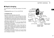
... one of these to [AC ADAPTER] Charging indicator Charging : Orange Finished : Green BC-177 (optional) Desktop charger 11 Otherwise the battery pack will not be used instead of the supplied AC adapter. Contact your dealer when the battery pack isn't charged. • The optional CP-12L and OPC-254L can only...
... one of these to [AC ADAPTER] Charging indicator Charging : Orange Finished : Green BC-177 (optional) Desktop charger 11 Otherwise the battery pack will not be used instead of the supplied AC adapter. Contact your dealer when the battery pack isn't charged. • The optional CP-12L and OPC-254L can only...
Instruction Manual
Page 20
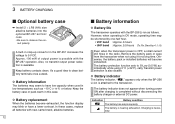
...9632; Battery information D Battery life The transceiver operates with the BP-257 operation. Remove the battery pack or case from the transceiver when not using 0°C (+32°F). Keep battery contacts clean. Charging is available. 3 BATTERY CHARGING ■ Optional battery case ➥ Install 2 ...However, when operating in DV mode, operating time may blink or have low capacity when used in this case. cally Transmit power selection is attached to S-Low (0.5 W) automatically while using it for a long time. D Battery indicator The battery indicator, " ," appears only ...
...9632; Battery information D Battery life The transceiver operates with the BP-257 operation. Remove the battery pack or case from the transceiver when not using 0°C (+32°F). Keep battery contacts clean. Charging is available. 3 BATTERY CHARGING ■ Optional battery case ➥ Install 2 ...However, when operating in DV mode, operating time may blink or have low capacity when used in this case. cally Transmit power selection is attached to S-Low (0.5 W) automatically while using it for a long time. D Battery indicator The battery indicator, " ," appears only ...

Instruction Manual
Page 21
... to a 24 V DC power source. • The voltage of the external power supply must be within 10-16 V DC when using either CP-12L, CP-19R or OPC254L, otherwise, use CP-12L,CP-19R or OPC-254L when connecting a regulated 12 V DC power supply. D Operating note • Power supply voltage... must be between 10.0-16.0 V DC. for 12 V cigarette lighter socket) or external DC power cable (OPC-254L) can be used for external power operation. BATTERY CHARGING 3 ■ External DC power operation An optional cigarette lighter cable (CP-12L or CP-19R; NEVER CONNECT OVER 16...
... to a 24 V DC power source. • The voltage of the external power supply must be within 10-16 V DC when using either CP-12L, CP-19R or OPC254L, otherwise, use CP-12L,CP-19R or OPC-254L when connecting a regulated 12 V DC power supply. D Operating note • Power supply voltage... must be between 10.0-16.0 V DC. for 12 V cigarette lighter socket) or external DC power cable (OPC-254L) can be used for external power operation. BATTERY CHARGING 3 ■ External DC power operation An optional cigarette lighter cable (CP-12L or CP-19R; NEVER CONNECT OVER 16...
Instruction Manual
Page 23
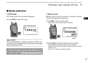
...the desired frequency. ➥ Push [VFO] to select VFO mode. 4 FREQUENCY AND CHANNEL SETTING ■ Mode selection D VFO mode VFO mode is used for operation on memory channels which store programmed frequencies. 4 q Push [MR] to select memory mode. • "µ " appears when memory ... desired memory channel. (p. 72) • See p. 74 for both transmitting and receiving are generated and controlled by other radio station when using a third party high-gain antenna. Frequencies for memory programming details. 15 VFOA MHz • VFO mode indication +DUP DTCS FM PRIO WX...
...the desired frequency. ➥ Push [VFO] to select VFO mode. 4 FREQUENCY AND CHANNEL SETTING ■ Mode selection D VFO mode VFO mode is used for operation on memory channels which store programmed frequencies. 4 q Push [MR] to select memory mode. • "µ " appears when memory ... desired memory channel. (p. 72) • See p. 74 for both transmitting and receiving are generated and controlled by other radio station when using a third party high-gain antenna. Frequencies for memory programming details. 15 VFOA MHz • VFO mode indication +DUP DTCS FM PRIO WX...
Instruction Manual
Page 24
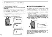
...* bands. (Some bands are programmed via the optional RS-92. 4 FREQUENCY AND CHANNEL SETTING D Call/TV*/Weather† channels Call channels are used for quick recall of most-often used frequencies. *Appears only when TV channels are not selectable for B band operation. See next page for the U.S.A. version only. qPush [CALL] several...
...* bands. (Some bands are programmed via the optional RS-92. 4 FREQUENCY AND CHANNEL SETTING D Call/TV*/Weather† channels Call channels are used for quick recall of most-often used frequencies. *Appears only when TV channels are not selectable for B band operation. See next page for the U.S.A. version only. qPush [CALL] several...

Instruction Manual
Page 26
.... [DIAL] 8 TS 18 +DUP DTCS FM PRIO WX EMR A 1 4 6 0 1 025 PSKIP µ 000 SET-TS:5.0kHz 5 kHz tuning step ■ Setting a frequency D Using the dial q Push [VFO] to the preset tuning steps. Push [MHz](VFO) to cancel it.) [DIAL] +DUP DTCS FM PRIO WX EMR A 1 4 6 0 1 025 [DIAL]... SETTING ■ Setting a tuning step The tuning step can be selected for the AM broadcast band only. The following tuning steps are available for the IC-92AD. • 5.0 kHz* • 6.25 kHz* • 8.33 kHz† • 9.0 kHz‡ • 10.0 kHz • 12.5 kHz • 15.0 kHz • ...
.... [DIAL] 8 TS 18 +DUP DTCS FM PRIO WX EMR A 1 4 6 0 1 025 PSKIP µ 000 SET-TS:5.0kHz 5 kHz tuning step ■ Setting a frequency D Using the dial q Push [VFO] to the preset tuning steps. Push [MHz](VFO) to cancel it.) [DIAL] +DUP DTCS FM PRIO WX EMR A 1 4 6 0 1 025 [DIAL]... SETTING ■ Setting a tuning step The tuning step can be selected for the AM broadcast band only. The following tuning steps are available for the IC-92AD. • 5.0 kHz* • 6.25 kHz* • 8.33 kHz† • 9.0 kHz‡ • 10.0 kHz • 12.5 kHz • 15.0 kHz • ...

Instruction Manual
Page 27
4 FREQUENCY AND CHANNEL SETTING D Using the keypad 1 The frequency can be directly set via numeric keys. • Entering 433.580 MHz • Entering 80.200 MHz • Changing 100 kHz ...
4 FREQUENCY AND CHANNEL SETTING D Using the keypad 1 The frequency can be directly set via numeric keys. • Entering 433.580 MHz • Entering 80.200 MHz • Changing 100 kHz ...
Instruction Manual
Page 29
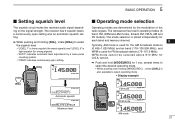
...received audio signal depending on the signal strength. The mode selection is stored independently for 4 each band and memory channel. 5 Typically, AM mode is used for the AM broadcast stations 6 (0.495-1.620 MHz) and air band (118-136.995 MHz), and WFM is tight squelch (for strong signals)....) , rotate [DIAL] is also available to select the squelch level. • "LEVEL 1" is loose squelch (for weak signals) and "LEVEL 9" is used for FM broadcast stations (76-107.9 MHz). 7 WFM mode cannot be selected above 810 MHz for 1 sec. several times to 9 select the desired operating mode...
...received audio signal depending on the signal strength. The mode selection is stored independently for 4 each band and memory channel. 5 Typically, AM mode is used for the AM broadcast stations 6 (0.495-1.620 MHz) and air band (118-136.995 MHz), and WFM is tight squelch (for strong signals)....) , rotate [DIAL] is also available to select the squelch level. • "LEVEL 1" is loose squelch (for weak signals) and "LEVEL 9" is used for FM broadcast stations (76-107.9 MHz). 7 WFM mode cannot be selected above 810 MHz for 1 sec. several times to 9 select the desired operating mode...
Instruction Manual
Page 30
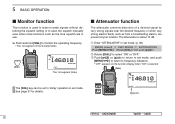
...MENU/ ]) (Rotate [DIAL]†, then push [ ](5)‡.) w Rotate [DIAL]† to select "ON" or "OFF." 5 BASIC OPERATION ■ Monitor function This function is used to listen to weak signals without disturbing the squelch setting or to open the squelch manually even when mute functions such as the tone squelch... are in use. ➥ Push and hold [SQL] to monitor the operating frequency. • The 1st segment of a desired signal by very strong ...
...MENU/ ]) (Rotate [DIAL]†, then push [ ](5)‡.) w Rotate [DIAL]† to select "ON" or "OFF." 5 BASIC OPERATION ■ Monitor function This function is used to listen to weak signals without disturbing the squelch setting or to open the squelch manually even when mute functions such as the tone squelch... are in use. ➥ Push and hold [SQL] to monitor the operating frequency. • The 1st segment of a desired signal by very strong ...
Instruction Manual
Page 31
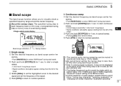
... regardless "Scope AF Output" setting in the MENU screen. 18 • If ghost waveform or audio appear, operate follow to less then 20 kHz when using band scope function. 15 • Even if a strong signal is present, it may not be muted in memory mode) is set to wide (ex.125... A B 1 4 5 7 8 025 PSKIP µ 000 10 11 12 • The receive audio during sweeping can be displayed on the band scope if the tuning step is used during sweep.
... regardless "Scope AF Output" setting in the MENU screen. 18 • If ghost waveform or audio appear, operate follow to less then 20 kHz when using band scope function. 15 • Even if a strong signal is present, it may not be muted in memory mode) is set to wide (ex.125... A B 1 4 5 7 8 025 PSKIP µ 000 10 11 12 • The receive audio during sweeping can be displayed on the band scope if the tuning step is used during sweep.

