Instruction Manual
Page 2
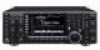
... may occur. FOR CLASS B UNINTENTIONAL RADIATORS This equipment has been tested and found to radio communications. FOREWORD Thank you agree with Icom's philosophy of "technology first." Equipment damage may cause harmful interference to comply with the limits for RTTY and PSK31 operations without ...not indicate an LCD malfunction. This manual contains impor- We hope you for the IC-7700. tant safety and operating instructions for making the IC-7700 your radio of your IC-7700. TRADEMARKS Icom, Icom Inc. and the logo are designed to correct the interference by one or more of...
... may occur. FOR CLASS B UNINTENTIONAL RADIATORS This equipment has been tested and found to radio communications. FOREWORD Thank you agree with Icom's philosophy of "technology first." Equipment damage may cause harmful interference to comply with the limits for RTTY and PSK31 operations without ...not indicate an LCD malfunction. This manual contains impor- We hope you for the IC-7700. tant safety and operating instructions for making the IC-7700 your radio of your IC-7700. TRADEMARKS Icom, Icom Inc. and the logo are designed to correct the interference by one or more of...
Instruction Manual
Page 3
...block any problems caused by children. NEVER expose the transceiver to the transceiver. R CAUTION! Avoid extension cords. cohol when cleaning the IC-7700, as on the top, rear or bottom of the transceiver. AVOID placing the transceiver against continuous high volume operation. ii R ...This may result in an electric shock or damage to operate this device, not expressly approved by holding rack mounting handle. Use Icom microphones only (supplied or optional). NEVER touch the transceiver top cover when transmitting continuously for advice. R CAUTION! NEVER put the...
...block any problems caused by children. NEVER expose the transceiver to the transceiver. R CAUTION! Avoid extension cords. cohol when cleaning the IC-7700, as on the top, rear or bottom of the transceiver. AVOID placing the transceiver against continuous high volume operation. ii R ...This may result in an electric shock or damage to operate this device, not expressly approved by holding rack mounting handle. Use Icom microphones only (supplied or optional). NEVER touch the transceiver top cover when transmitting continuously for advice. R CAUTION! NEVER put the...
Instruction Manual
Page 22
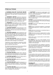
...3 [ANT 3] (p. 2-5) r ANTENNA CONNECTOR 4 [ANT 4] (p. 2-5) Accept a 50 Ω antenna with another Icom CI-V transceiver or receiver. !0 RS-232C TERMINAL [RS-232C] (p. 2-6) Connects an RS-232C cable, D-sub 9-pin to connect the IC-7700 to a PC. Deactivate the internal electronic keyer in keyer set mode. (p. 4-12) (+) (_) 1-12 t GROUND ... power supply ON and OFF. !2 AC POWER SOCKET [AC] (p. 2-5) Connects the supplied AC power cable to remotely control the IC-7700 without the optional CT-17, or for transceive operation with a PL-259 plug connector. i ETHERNET CONNECTOR (p. 16-6) Connects to...
...3 [ANT 3] (p. 2-5) r ANTENNA CONNECTOR 4 [ANT 4] (p. 2-5) Accept a 50 Ω antenna with another Icom CI-V transceiver or receiver. !0 RS-232C TERMINAL [RS-232C] (p. 2-6) Connects an RS-232C cable, D-sub 9-pin to connect the IC-7700 to a PC. Deactivate the internal electronic keyer in keyer set mode. (p. 4-12) (+) (_) 1-12 t GROUND ... power supply ON and OFF. !2 AC POWER SOCKET [AC] (p. 2-5) Connects the supplied AC power cable to remotely control the IC-7700 without the optional CT-17, or for transceive operation with a PL-259 plug connector. i ETHERNET CONNECTOR (p. 16-6) Connects to...
Instruction Manual
Page 30
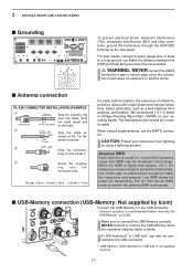
... specified frequency range and SWR may be a coaxial cable. The IC-7700 has an SWR meter to monitor the antenna SWR continuously. ■ USB-Memory connection (USB-Memory: Not supplied by Icom) Connect the USB-Memory* to protect the final transistors. NEVER connect...supplied by using a single antenna, use the [ANT1] connector. e solder solder Slide the connector body on your transceiver from lightning by Icom. 2-4 Make sure to match the transceiver and antenna. 2 INSTALLATION AND CONNECTIONS ■ Grounding To prevent electrical shock, television interference (TVI...
... specified frequency range and SWR may be a coaxial cable. The IC-7700 has an SWR meter to monitor the antenna SWR continuously. ■ USB-Memory connection (USB-Memory: Not supplied by Icom) Connect the USB-Memory* to protect the final transistors. NEVER connect...supplied by using a single antenna, use the [ANT1] connector. e solder solder Slide the connector body on your transceiver from lightning by Icom. 2-4 Make sure to match the transceiver and antenna. 2 INSTALLATION AND CONNECTIONS ■ Grounding To prevent electrical shock, television interference (TVI...
Instruction Manual
Page 69
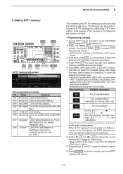
... 599-599 BK↵ RT4 DE+UR599 ↵QSL DE ICOM ICOM UR 599-599 BK↵ RT5 73 GL SK ↵73 GL SK↵ RT6 CQ CQ CQ ↵CQ CQ CQ DE ICOM ICOM ICOM K↵ RT7 RIG&ANT ↵MY TRANSCEIVER IS IC-7700 & ANTENNA IS A 3-ELEMENT TRIBAND YAGI.↵ RT8 EQUIP. &#...8629;MY RTTY EQUIPMENT IS INTERNAL FSK UNIT & DEMODULATOR OF THE IC-7700.↵ The contents of the memory is 70 characters per memory channel...
... 599-599 BK↵ RT4 DE+UR599 ↵QSL DE ICOM ICOM UR 599-599 BK↵ RT5 73 GL SK ↵73 GL SK↵ RT6 CQ CQ CQ ↵CQ CQ CQ DE ICOM ICOM ICOM K↵ RT7 RIG&ANT ↵MY TRANSCEIVER IS IC-7700 & ANTENNA IS A 3-ELEMENT TRIBAND YAGI.↵ RT8 EQUIP. &#...8629;MY RTTY EQUIPMENT IS INTERNAL FSK UNIT & DEMODULATOR OF THE IC-7700.↵ The contents of the memory is 70 characters per memory channel...

Instruction Manual
Page 77
...select the edit item between memory contents and memory name. ting only.) ✔ For your convenience When a PC keyboard is internal modulator & demodulator of the IC-7700.↵ The contents of the Channel 1 (PT1) is for often-used PSK information. i Push EXIT/SET to set - Key selection Editable characters ABC A ... 599 BK↵ PT5 73 GL SK ↵73 GL SK↵ PT6 CQ CQ CQ ↵CQ CQ CQ DE Icom Icom Icom K↵ PT7 RIG&ANT ↵My transceiver is IC-7700 & Antenna is a 3-element triband yagi.↵ PT8 EQUIP. ↵My PSK equipment is connected to [USB] connector on...
...select the edit item between memory contents and memory name. ting only.) ✔ For your convenience When a PC keyboard is internal modulator & demodulator of the IC-7700.↵ The contents of the Channel 1 (PT1) is for often-used PSK information. i Push EXIT/SET to set - Key selection Editable characters ABC A ... 599 BK↵ PT5 73 GL SK ↵73 GL SK↵ PT6 CQ CQ CQ ↵CQ CQ CQ DE Icom Icom Icom K↵ PT7 RIG&ANT ↵My transceiver is IC-7700 & Antenna is a 3-element triband yagi.↵ PT8 EQUIP. ↵My PSK equipment is connected to [USB] connector on...
Instruction Manual
Page 171
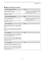
... (continued) External Keypad (VOICE) Sets the external keypad for the equivalent circuit of connected transceivers (or receivers) and vice versa. 12-17 on the IC-7700 automatically changes those of an external keypad and connection. See page 2-7 for voice message transmission capability ON and OFF. Auto CI-V Address To distinguish equipment...default) External Keypad (KEYER) Sets the external keypad for keyer memory transmission capability ON and OFF. SET MODE 12 ■ Others set according to other Icom HF transceivers or receivers. See page 2-7 for each CI-V transceiver has its own...
... (continued) External Keypad (VOICE) Sets the external keypad for the equivalent circuit of connected transceivers (or receivers) and vice versa. 12-17 on the IC-7700 automatically changes those of an external keypad and connection. See page 2-7 for voice message transmission capability ON and OFF. Auto CI-V Address To distinguish equipment...default) External Keypad (KEYER) Sets the external keypad for keyer memory transmission capability ON and OFF. SET MODE 12 ■ Others set according to other Icom HF transceivers or receivers. See page 2-7 for each CI-V transceiver has its own...
Instruction Manual
Page 173
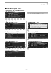
.... If you make a mistake, the IC-7700 may be the only way to the firmware download homepage and/or the instruction manual for the correct procedures in updating the firmware. You undertake the updating of the firmware at Icom Inc, (Japan) may not operate properly...; Setting load screen (p. 12-23) F-1 F-2 F-3 F-4 F-5 F-6 F-7 • Load option set mode (p. 12-21) • Firmware update (p. 16-4) Updating the firmware is not supplied by Icom. SET MODE 12 ■ USB-Memory set menu D USB-Memory set screen arrangement • USB-Memory set menu The USB-Memory is very risky.
.... If you make a mistake, the IC-7700 may be the only way to the firmware download homepage and/or the instruction manual for the correct procedures in updating the firmware. You undertake the updating of the firmware at Icom Inc, (Japan) may not operate properly...; Setting load screen (p. 12-23) F-1 F-2 F-3 F-4 F-5 F-6 F-7 • Load option set mode (p. 12-21) • Firmware update (p. 16-4) Updating the firmware is not supplied by Icom. SET MODE 12 ■ USB-Memory set menu D USB-Memory set screen arrangement • USB-Memory set menu The USB-Memory is very risky.
Instruction Manual
Page 190
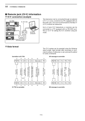
... (see command table) BCD code data for some commands. ct- 17 personal computer Up to 4 Icom CI-V transceivers or receivers can be operated using set mode. mini-plug cable D Data format Controller to IC-7700 q w ert FE FE 74 E0 Cn Sc y Data area The CI-V system can be connected... or memory number entry End of message code (fixed) (fixed) FE FE E0 74 Cn Sc Data area FD q w ert y u IC-7700 to controller FE FE E0 74 FA FD NG message to command numbers. The Icom Communications Interface-V (CI-V) controls the transceiver. Data formats differ according to controller 14-2
... (see command table) BCD code data for some commands. ct- 17 personal computer Up to 4 Icom CI-V transceivers or receivers can be operated using set mode. mini-plug cable D Data format Controller to IC-7700 q w ert FE FE 74 E0 Cn Sc y Data area The CI-V system can be connected... or memory number entry End of message code (fixed) (fixed) FE FE E0 74 Cn Sc Data area FD q w ert y u IC-7700 to controller FE FE E0 74 FA FD NG message to command numbers. The Icom Communications Interface-V (CI-V) controls the transceiver. Data formats differ according to controller 14-2
Instruction Manual
Page 204
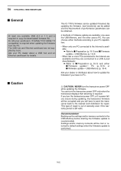
...either methods according to your PC capabilities. • When only one PC connected to the Internet is available ➥ Refer to the nearest Icom distributor for details. PC (p. 16-6) or ■ Firmware update- This type of repair is out of firmware update are not supplied by... update is required. The USB hub and Ethernet card/board are available: one available USB (2.0 or 1.1) port is performed. 16-2 The IC-7700's firmware can turn the transceiver power OFF, or if a power failure occurs during updating, the transceiver firmware will be updated if desired.
...either methods according to your PC capabilities. • When only one PC connected to the Internet is available ➥ Refer to the nearest Icom distributor for details. PC (p. 16-6) or ■ Firmware update- This type of repair is out of firmware update are not supplied by... update is required. The USB hub and Ethernet card/board are available: one available USB (2.0 or 1.1) port is performed. 16-2 The IC-7700's firmware can turn the transceiver power OFF, or if a power failure occurs during updating, the transceiver firmware will be updated if desired.
Instruction Manual
Page 205
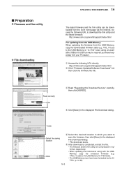
...dialog. • File download starts. http://www.icom.co.jp/world/support/index.html For updating from the USB-Memory When updating the firmware from the USB-Memory, copy the downloaded firmware data (e.g. 7700_110.dat) to the USB-Memory (in "IC-7700" folder) using with the USBMemory, copy the ...USB hub may be downloaded from your PC dealer). http://www.icom.co.jp/world/support/index.html w Click "Firmware Updates/Software Downloads" link then click the firmware file link. q Access the following URL to the USB-Memory IC-7700 folder. • The USB-Memory must have been formatted by ...
...dialog. • File download starts. http://www.icom.co.jp/world/support/index.html For updating from the USB-Memory When updating the firmware from the USB-Memory, copy the downloaded firmware data (e.g. 7700_110.dat) to the USB-Memory (in "IC-7700" folder) using with the USBMemory, copy the ...USB hub may be downloaded from your PC dealer). http://www.icom.co.jp/world/support/index.html w Click "Firmware Updates/Software Downloads" link then click the firmware file link. q Access the following URL to the USB-Memory IC-7700 folder. • The USB-Memory must have been formatted by ...
Instruction Manual
Page 210
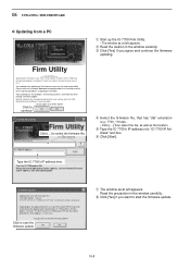
Also all of the above? Making a backup file of the firmware at Icom Inc.(Japan) may be updated when rebooting the IC-7700 and this will take approx. 2 minutes. Type the IC-7700's IP address here. When the normal operational screen appears, set conditions, the memory contents, ...you wish to seleVcetrtshioen 1fi.r0m0 ware file. (C) 2007 Icom Inc. continue IC-7700 Firm Utility Firmware File Name IC-7700 IP Address Click [...] to start the firmware update. 16-8 Turn the IC-7700 power ON. t Type the IC-7700's IP address into "IC-7700 IP Ad- Click to fix it. 16 UPDATING THE ...
Also all of the above? Making a backup file of the firmware at Icom Inc.(Japan) may be updated when rebooting the IC-7700 and this will take approx. 2 minutes. Type the IC-7700's IP address here. When the normal operational screen appears, set conditions, the memory contents, ...you wish to seleVcetrtshioen 1fi.r0m0 ware file. (C) 2007 Icom Inc. continue IC-7700 Firm Utility Firmware File Name IC-7700 IP Address Click [...] to start the firmware update. 16-8 Turn the IC-7700 power ON. t Type the IC-7700's IP address into "IC-7700 IP Ad- Click to fix it. 16 UPDATING THE ...
Instruction Manual
Page 211
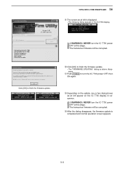
... two dialog boxes as above disappears. !1 Push POWER to turn power OFF. !2 Depending on the IC-7700 display in the IC-7700 display. DO NOT turn the IC-7700 power OFF at this stage. Please wait for the main CPU is completed and normal operation screen appears... Transfer in progress... RWARNING!: NEVER turn the IC-7700 power OFF until the normal operational screen appears. !0 Click [OK] to the IC-7700. The transceiver firmware will take approx. 2 minutes. SCOPE-DSP UPDATING... WARNING! Transfer successful. Version 1.00 (C) 2007 Icom Inc. Please wait for 10sec. RWARNING!: NEVER...
... two dialog boxes as above disappears. !1 Push POWER to turn power OFF. !2 Depending on the IC-7700 display in the IC-7700 display. DO NOT turn the IC-7700 power OFF at this stage. Please wait for the main CPU is completed and normal operation screen appears... Transfer in progress... RWARNING!: NEVER turn the IC-7700 power OFF until the normal operational screen appears. !0 Click [OK] to the IC-7700. The transceiver firmware will take approx. 2 minutes. SCOPE-DSP UPDATING... WARNING! Transfer successful. Version 1.00 (C) 2007 Icom Inc. Please wait for 10sec. RWARNING!: NEVER...


