
Instruction Manual
Page 2
...of the transceiver. The heatsink will soon become hot when operating the transceiver continuously for Commercially Available Amateur Radio Equipment). Use Icom microphones only (supplied or optional). i NEVER attach an antenna or internal antenna connector during transmission. Be aware that ... cause a fire or ruin the transceiver. NEVER expose the transceiver to the transceiver if left there for the IC-718. BE CAREFUL! Other manufacturer's microphones have different pin assignments, and connection to prevent erroneous indications. This manual contains important...
...of the transceiver. The heatsink will soon become hot when operating the transceiver continuously for Commercially Available Amateur Radio Equipment). Use Icom microphones only (supplied or optional). i NEVER attach an antenna or internal antenna connector during transmission. Be aware that ... cause a fire or ruin the transceiver. NEVER expose the transceiver to the transceiver if left there for the IC-718. BE CAREFUL! Other manufacturer's microphones have different pin assignments, and connection to prevent erroneous indications. This manual contains important...

Instruction Manual
Page 3
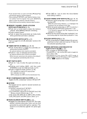
... view 59 s Bottom view 59 SUPPLIED ACCESSORIES q w The transceiver comes with the following accessories. q DC power cable 1 w Hand microphone (HM-36 1 e Fuse (FGB 20 A; internal use 1 er 1 Qty. 1 TABLE OF CONTENTS IMPORTANT i EXPLICIT DEFINITIONS i PRECAUTIONS i 1 TABLE OF CONTENTS 1 SUPPLIED ACCESSORIES 1 2 PANEL DESCRIPTION 2 - 8 s Front panel 2 s Function display 5 s Rear panel 6 s Microphone (HM-36...
... view 59 s Bottom view 59 SUPPLIED ACCESSORIES q w The transceiver comes with the following accessories. q DC power cable 1 w Hand microphone (HM-36 1 e Fuse (FGB 20 A; internal use 1 er 1 Qty. 1 TABLE OF CONTENTS IMPORTANT i EXPLICIT DEFINITIONS i PRECAUTIONS i 1 TABLE OF CONTENTS 1 SUPPLIED ACCESSORIES 1 2 PANEL DESCRIPTION 2 - 8 s Front panel 2 s Function display 5 s Rear panel 6 s Microphone (HM-36...
Instruction Manual
Page 5
... ALC level. • SWR: indicates the SWR over the transmission line. !6 MIC COMPRESSOR SWITCH [COMP] (p. 27) Toggles the Mic. during SSB mode to toggle be used for 1 sec.
... ALC level. • SWR: indicates the SWR over the transmission line. !6 MIC COMPRESSOR SWITCH [COMP] (p. 27) Toggles the Mic. during SSB mode to toggle be used for 1 sec.
Instruction Manual
Page 7
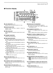
...(p. 16) "VFO A" or "B" appears when VFO mode is selected. i NOISE REDUCTION INDICATOR (p. 23) Appears when the optional Noise Reduction function is in use. !4 RIT INDICATOR (p. 21) Appears when the RIT function is selected. !9 MODE INDICATORS (p. 20) Indicates the selected operating mode. 5 e TUNE INDICATOR ... • Flashes when scan is open. t FUNCTION INDICATORS ➥ "P.AMP" appears when antenna preamp is in use. ➥ "ATT" appears when the attenuator function is in use. ➥ "NB" appears when the Noise Blanker function is turned ON. ➥ "BK" appears when the...
...(p. 16) "VFO A" or "B" appears when VFO mode is selected. i NOISE REDUCTION INDICATOR (p. 23) Appears when the optional Noise Reduction function is in use. !4 RIT INDICATOR (p. 21) Appears when the RIT function is selected. !9 MODE INDICATORS (p. 20) Indicates the selected operating mode. 5 e TUNE INDICATOR ... • Flashes when scan is open. t FUNCTION INDICATORS ➥ "P.AMP" appears when antenna preamp is in use. ➥ "ATT" appears when the attenuator function is in use. ➥ "NB" appears when the Noise Blanker function is turned ON. ➥ "BK" appears when the...
Instruction Manual
Page 8
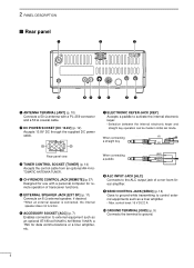
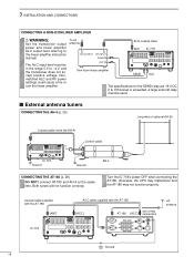
... transmitting to external equipment such as a liner amplifier. • Max. r CI-V REMOTE CONTROL JACK [REMOTE] (p. 57) Designed for use with a PL-259 connector and a 50 Ω coaxial cable. y ACCESSORY SOCKET [ACC] (p. 7) Enables connection to control external equipments such as... an optional AT-180 AUTOMATIC ANTENNA TUNER, a TNC for remote operation of a non-Icom linear amplifier. When connecting (⊕) a straight key Rear panel view e TUNER CONTROL SOCKET [TUNER] (p. 14) Accepts the control...
... transmitting to external equipment such as a liner amplifier. • Max. r CI-V REMOTE CONTROL JACK [REMOTE] (p. 57) Designed for use with a PL-259 connector and a 50 Ω coaxial cable. y ACCESSORY SOCKET [ACC] (p. 7) Enables connection to control external equipments such as... an optional AT-180 AUTOMATIC ANTENNA TUNER, a TNC for remote operation of a non-Icom linear amplifier. When connecting (⊕) a straight key Rear panel view e TUNER CONTROL SOCKET [TUNER] (p. 14) Accepts the control...
Instruction Manual
Page 11
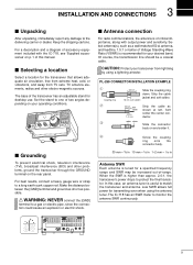
... jacket and soft solder. 10 mm Soft solder 1-2 mm solder solder Strip the cable as possible. The IC-718 has an SWR meter to protect the final transistor. s Selecting a location Select a location for desktop use. Make the distance between the [GND] terminal and ground as short as shown at left. CAUTION: Protect...
... jacket and soft solder. 10 mm Soft solder 1-2 mm solder solder Strip the cable as possible. The IC-718 has an SWR meter to protect the final transistor. s Selecting a location Select a location for desktop use. Make the distance between the [GND] terminal and ground as short as shown at left. CAUTION: Protect...
Instruction Manual
Page 12
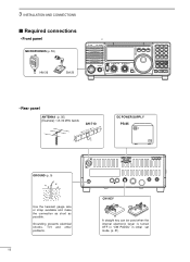
Grounding prevents electrical shocks, TVI and other problems. 10 CW KEY A straight key can be used when the internal electronic keyer is turned OFF in "CW PADDL" in initial set mode. (p. 31) CL ˛ M V 7 8 9 SPL SCN VOX . 0 NR ANF F-INP ENT ... approx. 24.5 m; 80.3 ft DC POWER SUPPLY PS-85 GROUND (p. 9) Use the heaviest gauge wire or strap available and make the connection as short as possible. 3 INSTALLATION AND CONNECTIONS s Required connections • Front panel MICROPHONES (p. 55) HM-36 SM-20 IC-718 MODE FIL TS PWR AF RF/SQL RIT SHIFT MIC PHONES...
Grounding prevents electrical shocks, TVI and other problems. 10 CW KEY A straight key can be used when the internal electronic keyer is turned OFF in "CW PADDL" in initial set mode. (p. 31) CL ˛ M V 7 8 9 SPL SCN VOX . 0 NR ANF F-INP ENT ... approx. 24.5 m; 80.3 ft DC POWER SUPPLY PS-85 GROUND (p. 9) Use the heaviest gauge wire or strap available and make the connection as short as possible. 3 INSTALLATION AND CONNECTIONS s Required connections • Front panel MICROPHONES (p. 55) HM-36 SM-20 IC-718 MODE FIL TS PWR AF RF/SQL RIT SHIFT MIC PHONES...
Instruction Manual
Page 13
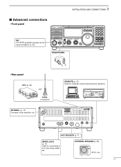
... AH-2b or long wire ANTENNA (p. 13) Connects a liner amprifier, etc. [REMOTE] (p. 57) Used for connecting a non-Icom linear amplifier. 3 INSTALLATION AND CONNECTIONS s Advanced connections • Front panel MIC The AFSK modulation signal can be input from [MIC]. (p. 33) IC-718 MODE FIL TS PWR AF RF/SQL RIT SHIFT MIC PHONES LOCK 1 2 3 V/M A=B A/B 4 5 6 MW...
... AH-2b or long wire ANTENNA (p. 13) Connects a liner amprifier, etc. [REMOTE] (p. 57) Used for connecting a non-Icom linear amplifier. 3 INSTALLATION AND CONNECTIONS s Advanced connections • Front panel MIC The AFSK modulation signal can be input from [MIC]. (p. 33) IC-718 MODE FIL TS PWR AF RF/SQL RIT SHIFT MIC PHONES LOCK 1 2 3 V/M A=B A/B 4 5 6 MW...
Instruction Manual
Page 14
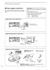
..., check the following important items. Make sure: • The [POWER] switch is OFF. • Output voltage of the power source is 12-15 V when you use a non-Icom power supply. • DC power cable polarity is correct. Crimp 12 V battery Supplied DC power cable Solder Fuses NEVER connect to an AC outlet... 1234 DC power socket Connect to a battery without supplied DC fuses, otherwise the fire hazard may occur. 12 3 INSTALLATION AND CONNECTIONS s Power supply connections Use an optional PS-85 DC POWER SUPPLY when operating the IC-718 with AC power.
..., check the following important items. Make sure: • The [POWER] switch is OFF. • Output voltage of the power source is 12-15 V when you use a non-Icom power supply. • DC power cable polarity is correct. Crimp 12 V battery Supplied DC power cable Solder Fuses NEVER connect to an AC outlet... 1234 DC power socket Connect to a battery without supplied DC fuses, otherwise the fire hazard may occur. 12 3 INSTALLATION AND CONNECTIONS s Power supply connections Use an optional PS-85 DC POWER SUPPLY when operating the IC-718 with AC power.
Instruction Manual
Page 16
...cable supplied with the AT-180 [ACC] one of two AT-180 [ACC] connectors HF antenna IC-718 13 9 10 11 12 5678 1234 Ground 14 If this level is exceeded, a large external relay must be used. The ALC input level must be in the range 0 V to the linear amplifier ... Ground AH-4 CONNECTING THE AT-180 (p. 28) DO NOT! Turn the IC-718's power OFF when connecting the AT-180, otherwise, the CPU may malfunction and the AT-180 may not function properly. 3 INSTALLATION AND CONNECTIONS CONNECTING A NON-ICOM LINER AMPLIFIER R WARNING: Set the transceiver output power and linear amplifier ALC ...
...cable supplied with the AT-180 [ACC] one of two AT-180 [ACC] connectors HF antenna IC-718 13 9 10 11 12 5678 1234 Ground 14 If this level is exceeded, a large external relay must be used. The ALC input level must be in the range 0 V to the linear amplifier ... Ground AH-4 CONNECTING THE AT-180 (p. 28) DO NOT! Turn the IC-718's power OFF when connecting the AT-180, otherwise, the CPU may malfunction and the AT-180 may not function properly. 3 INSTALLATION AND CONNECTIONS CONNECTING A NON-ICOM LINER AMPLIFIER R WARNING: Set the transceiver output power and linear amplifier ALC ...
Instruction Manual
Page 17
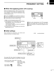
...) Before first applying power, make sure all programmed contents in memory channels and returns programmed values in the figure below. Then, reset the transceiver using the following indicators appear, turn power ON. • The internal CPU is reset. • The transceiver displays its initial VFO frequencies when resetting is OFF...
...) Before first applying power, make sure all programmed contents in memory channels and returns programmed values in the figure below. Then, reset the transceiver using the following indicators appear, turn power ON. • The internal CPU is reset. • The transceiver displays its initial VFO frequencies when resetting is OFF...
Instruction Manual
Page 18
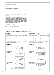
... two VFOs, specially suited for that VFO appears. The frequency is selected again. Changed frequency (14.123 MHz) appears. The IC-718 VFO can also change the frequency with the tuning dial and select the operating mode with the [MODE] switch or call up previously...operating mode like a VFO. VFO is changed . When the VFO is selected. Memory mode is selected from another VFO or memory mode, the last-used frequency and operating mode for split frequency opration. Changed frequency (14.123 MHz) does not appear and memorized frequency (14.100 MHz) appears instead....
... two VFOs, specially suited for that VFO appears. The frequency is selected again. Changed frequency (14.123 MHz) appears. The IC-718 VFO can also change the frequency with the tuning dial and select the operating mode with the [MODE] switch or call up previously...operating mode like a VFO. VFO is changed . When the VFO is selected. Memory mode is selected from another VFO or memory mode, the last-used frequency and operating mode for split frequency opration. Changed frequency (14.123 MHz) does not appear and memorized frequency (14.100 MHz) appears instead....
Instruction Manual
Page 19
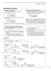
...• If a key is mistakenly pushed, push [SET] (or any key except keypad) and start again from the beginning. 4 FREQUENCY SETTING s Frequency setting D Using the tuning dial q Push [∫ UP] or [√ DN] one or more times to enter the frequency dig- q Push [F-INP/ENT], then push the ...entering the same MHz digits as described below. e Push the numeral keys to select the desired ham band. • For general coverage receiver use The IC-718 has a general coverage receiver band. e Rotate the tuning dial to set the desired frequency Note: Even if you select the ham band, ...
...• If a key is mistakenly pushed, push [SET] (or any key except keypad) and start again from the beginning. 4 FREQUENCY SETTING s Frequency setting D Using the tuning dial q Push [∫ UP] or [√ DN] one or more times to enter the frequency dig- q Push [F-INP/ENT], then push the ...entering the same MHz digits as described below. e Push the numeral keys to select the desired ham band. • For general coverage receiver use The IC-718 has a general coverage receiver band. e Rotate the tuning dial to set the desired frequency Note: Even if you select the ham band, ...
Instruction Manual
Page 20
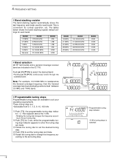
...; UP]/[√ DN] continuously scrolls through the available bands. 4 FREQUENCY SETTING D Band stacking resister The band stacking register automatically stores the last frequency and mode used for each band. t Rotate the tuning dial to the set tuning step. BAND 1.9 MHz 3.5 MHz 7 MHz 10 MHz 14 MHz General BAND 1.91000 MHz 3.55000... and 7 MHz band. Note: For example, if 6.10000 MHz is selected. 18 w Push [TS] for contest operation, etc. These tuning steps are included in the IC-718.
...; UP]/[√ DN] continuously scrolls through the available bands. 4 FREQUENCY SETTING D Band stacking resister The band stacking register automatically stores the last frequency and mode used for each band. t Rotate the tuning dial to the set tuning step. BAND 1.9 MHz 3.5 MHz 7 MHz 10 MHz 14 MHz General BAND 1.91000 MHz 3.55000... and 7 MHz band. Note: For example, if 6.10000 MHz is selected. 18 w Push [TS] for contest operation, etc. These tuning steps are included in the IC-718.
Instruction Manual
Page 22
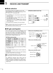
...; When set as the [RF/SQL] control Maximum RF gain Squelch is open . 5 RECEIVE AND TRANSMIT s Mode selection The following modes are available in the IC-718: SSB (LSB/USB), CW, CW REV (CW reverse), RTTY, RTTY REV (RTTY reverse)and AM. ➥ Push [MODE] one or more times to select ... squelch threshold S-meter squelch • When set as the [RF] control Maximum RF gain Adjustable range Minimum RF gain 20 s RF gain and Squelch The IC-718 uses the same control, [RF/SQL], to adjust either the RF gain or the squelch. [RF/SQL] adjusts either the RF gain or the squelch depending...
...; When set as the [RF/SQL] control Maximum RF gain Squelch is open . 5 RECEIVE AND TRANSMIT s Mode selection The following modes are available in the IC-718: SSB (LSB/USB), CW, CW REV (CW reverse), RTTY, RTTY REV (RTTY reverse)and AM. ➥ Push [MODE] one or more times to select ... squelch threshold S-meter squelch • When set as the [RF] control Maximum RF gain Adjustable range Minimum RF gain 20 s RF gain and Squelch The IC-718 uses the same control, [RF/SQL], to adjust either the RF gain or the squelch. [RF/SQL] adjusts either the RF gain or the squelch depending...
Instruction Manual
Page 23
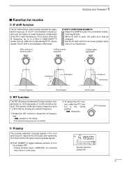
The IF shift is used, the audio tone may reduce in some cases. RIT off position ï Preamp The preamp amplifies received signals in AM mode. w To cancel the RIT ...
The IF shift is used, the audio tone may reduce in some cases. RIT off position ï Preamp The preamp amplifies received signals in AM mode. w To cancel the RIT ...
Instruction Manual
Page 24
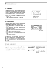
... dB. so that generated by automobile ignition systems. q Push the [NB] switch to turn the noise blanker function OFF. • [NB] indicator disappears. • When using the noise blanker, received signals may be distorted if they are excessively strong. • The noise blanker function in AM mode can be turned ON...
... dB. so that generated by automobile ignition systems. q Push the [NB] switch to turn the noise blanker function OFF. • [NB] indicator disappears. • When using the noise blanker, received signals may be distorted if they are excessively strong. • The noise blanker function in AM mode can be turned ON...
Instruction Manual
Page 25
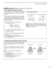
... then the desired signals are moving. Unwanted tone frequency Particular frequency is installed (DSP appears in the function display), an auto notch function can be used . w Push [ANF] to enter the noise reduction level setting condition. Set the [NR] level for 1 sec. r Push [NR] to adjust the noise reduction level. e Rotate... noise. The noise reduction function reduces noise components and picks out desired signals which are buried in the function display), noise reduction function can be used .
... then the desired signals are moving. Unwanted tone frequency Particular frequency is installed (DSP appears in the function display), an auto notch function can be used . w Push [ANF] to enter the noise reduction level setting condition. Set the [NR] level for 1 sec. r Push [NR] to adjust the noise reduction level. e Rotate... noise. The noise reduction function reduces noise components and picks out desired signals which are buried in the function display), noise reduction function can be used .
Instruction Manual
Page 26
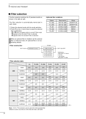
... 500* 250* WIDE 6 K* 6 K* 6 K* CW NORMAL 2.4 K 2.4 K 2.4 K NARROW 500 250 WIDE 6 K* 6 K* 6 K* RTTY NORMAL 2.4 K 2.4 K 2.4 K NARROW 500 250 WIDE AM NORMAL 6 K 6 K 6 K NARROW 2.4 K 2.4 K 500* 2.4 K 250* Note: *This selection can be used when the expanded filter selection function is not selected by default. • Filter construction 2nd IF signal CFWS450HT (6 kHz)*** Through FL-65 (2.4 kHz)* FL-257...
... 500* 250* WIDE 6 K* 6 K* 6 K* CW NORMAL 2.4 K 2.4 K 2.4 K NARROW 500 250 WIDE 6 K* 6 K* 6 K* RTTY NORMAL 2.4 K 2.4 K 2.4 K NARROW 500 250 WIDE AM NORMAL 6 K 6 K 6 K NARROW 2.4 K 2.4 K 500* 2.4 K 250* Note: *This selection can be used when the expanded filter selection function is not selected by default. • Filter construction 2nd IF signal CFWS450HT (6 kHz)*** Through FL-65 (2.4 kHz)* FL-257...
Instruction Manual
Page 27
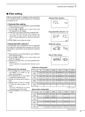
.... RTTY - - - 52A (500) 53A (250) - - - 222 (1.8 K) - - - 5 RECEIVE AND TRANSMIT s Filter setting When an optional filter is selected, the expanded filter selection can be used. • Narrow filter setting • Wide/narrow filter selecting r Push [UP Y] one or more times until "WIDE ✻✻" or "NAR ✻✻...
.... RTTY - - - 52A (500) 53A (250) - - - 222 (1.8 K) - - - 5 RECEIVE AND TRANSMIT s Filter setting When an optional filter is selected, the expanded filter selection can be used. • Narrow filter setting • Wide/narrow filter selecting r Push [UP Y] one or more times until "WIDE ✻✻" or "NAR ✻✻...


