Installation Guide
Page 5
... Utility program 31 Using ServeRAID Manager 32 Using the Remote Supervisor Adapter II Web interface 34 Chapter 5. Introduction 1 The IBM System x Documentation CD 2 Hardware and software requirements 2 Using the Documentation Browser 2 Notices and statements in this document 3 ...Hard disk drive problems 41 Intermittent problems 42 © Copyright IBM Corp. 2009 iii Contents Safety v Chapter 1. Installing options 7 Installation guidelines 7 System reliability guidelines 8 Working inside the server with the power on the server 26 Turning off the server 26 Chapter 4....
... Utility program 31 Using ServeRAID Manager 32 Using the Remote Supervisor Adapter II Web interface 34 Chapter 5. Introduction 1 The IBM System x Documentation CD 2 Hardware and software requirements 2 Using the Documentation Browser 2 Notices and statements in this document 3 ...Hard disk drive problems 41 Intermittent problems 42 © Copyright IBM Corp. 2009 iii Contents Safety v Chapter 1. Installing options 7 Installation guidelines 7 System reliability guidelines 8 Working inside the server with the power on the server 26 Turning off the server 26 Chapter 4....

Installation Guide
Page 6
... Voluntary Control Council for Interference (VCCI) statement . . . 69 Korean Class A warning statement 69 Index 71 iv IBM System x3755 Types 8877 and 7163: Installation Guide Keyboard, mouse, or pointing-device problems 42 Memory problems 44 Microprocessor problems 45 Monitor problems 45 Optional-device... problems 48 Power problems 49 Serial port problems 50 ServerGuide problems 51 Software problems 51 Universal ...
... Voluntary Control Council for Interference (VCCI) statement . . . 69 Korean Class A warning statement 69 Index 71 iv IBM System x3755 Types 8877 and 7163: Installation Guide Keyboard, mouse, or pointing-device problems 42 Memory problems 44 Microprocessor problems 45 Monitor problems 45 Optional-device... problems 48 Power problems 49 Serial port problems 50 ServerGuide problems 51 Software problems 51 Universal ...
Installation Guide
Page 9
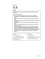
... cables as described in the installation and configuration procedures. Turn everything OFF. 2. Attach power cords to a properly wired and grounded electrical outlet. Remove signal cables from outlet. 3. v Connect all power cords to outlet. 5. v Disconnect the attached power cords, telecommunications systems, networks, and modems before you open the device covers, unless instructed otherwise in the...
... cables as described in the installation and configuration procedures. Turn everything OFF. 2. Attach power cords to a properly wired and grounded electrical outlet. Remove signal cables from outlet. 3. v Connect all power cords to outlet. 5. v Disconnect the attached power cords, telecommunications systems, networks, and modems before you open the device covers, unless instructed otherwise in the...

Installation Guide
Page 11
To remove all electrical current from the device, ensure that all power cords are disconnected from the power source. 2 1 Safety ix Statement 5: ≥ 55 kg (121.2 lb) CAUTION: The power control button on the device and the power switch on the power supply do not turn off the electrical current supplied to the device. The device also might have more than one power cord. Statement 4: ≥ 18 kg (39.7 lb) ≥ 32 kg (70.5 lb) CAUTION: Use safe practices when lifting.
To remove all electrical current from the device, ensure that all power cords are disconnected from the power source. 2 1 Safety ix Statement 5: ≥ 55 kg (121.2 lb) CAUTION: The power control button on the device and the power switch on the power supply do not turn off the electrical current supplied to the device. The device also might have more than one power cord. Statement 4: ≥ 18 kg (39.7 lb) ≥ 32 kg (70.5 lb) CAUTION: Use safe practices when lifting.

Installation Guide
Page 12
If you suspect a problem with one of rack-mounted devices. Statement 27: CAUTION: Hazardous moving parts are present inside these parts, contact a service technician. Hazardous voltage, current, and energy levels are nearby. There are no serviceable parts inside any component that has the following label attached. x IBM System x3755 Types 8877 and 7163: Installation Guide Statement 8: CAUTION: Never remove the cover on top of these components. Statement 26: CAUTION: Do not place any object on a power supply or any part that has this label attached.
If you suspect a problem with one of rack-mounted devices. Statement 27: CAUTION: Hazardous moving parts are present inside these parts, contact a service technician. Hazardous voltage, current, and energy levels are nearby. There are no serviceable parts inside any component that has the following label attached. x IBM System x3755 Types 8877 and 7163: Installation Guide Statement 8: CAUTION: Never remove the cover on top of these components. Statement 26: CAUTION: Do not place any object on a power supply or any part that has this label attached.
Installation Guide
Page 16
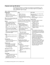
... - 1500 watts at 220 V ac input - 750 watts at 110 V ac input v Upgradeable to two power supplies (redundant at 220 V ac only) 4 IBM System x3755 Types 8877 and 7163: Installation Guide Memory: v Minimum: 1 GB depending on server model, expandable to 128 GB v Type: 667 MHz, registered, ECC, PC2-5300 double...Express x8 (full-length) v One PCI Express x4 (full-length) v Two 100 MHz/64-bit PCI-X (full-length) v One HTX (half-length) Upgradeable microcode: System BIOS, diagnostics, service processor, BMC, CPLD, and SAS microcode Size: v 4U v Height: 178 mm (7 in.) v Depth: 711 mm (28 in.) v Width:...
... - 1500 watts at 220 V ac input - 750 watts at 110 V ac input v Upgradeable to two power supplies (redundant at 220 V ac only) 4 IBM System x3755 Types 8877 and 7163: Installation Guide Memory: v Minimum: 1 GB depending on server model, expandable to 128 GB v Type: 667 MHz, registered, ECC, PC2-5300 double...Express x8 (full-length) v One PCI Express x4 (full-length) v Two 100 MHz/64-bit PCI-X (full-length) v One HTX (half-length) Upgradeable microcode: System BIOS, diagnostics, service processor, BMC, CPLD, and SAS microcode Size: v 4U v Height: 178 mm (7 in.) v Depth: 711 mm (28 in.) v Width:...

Installation Guide
Page 18
Top cover DIMM Hot-swap fan Microprocessor/ memory card Hot-swap power supply I/O board Passthru card DVD drive Operator information panel Hot-swap hard disk drive Hard disk drive filler panel Power supply filler 6 IBM System x3755 Types 8877 and 7163: Installation Guide Note: The illustrations in this document might differ slightly from your hardware.
Top cover DIMM Hot-swap fan Microprocessor/ memory card Hot-swap power supply I/O board Passthru card DVD drive Operator information panel Hot-swap hard disk drive Hard disk drive filler panel Power supply filler 6 IBM System x3755 Types 8877 and 7163: Installation Guide Note: The illustrations in this document might differ slightly from your hardware.

Installation Guide
Page 19
... object, observe the following information: v Read the safety information that you install your new server, take the opportunity to install or replace hot-swap power supplies, hot-swap fans, or hot-plug Universal Serial Bus (USB) devices. Use a slow lifting force. Never move suddenly or twist when you...the server is too heavy for you must start the server while the cover is removed, make changes to http://www.ibm.com/servers/eserver/support/xseries/index.html, select System x3755 from or install it in the server, open or close a latch, and so on a component indicates touch points,...
... object, observe the following information: v Read the safety information that you install your new server, take the opportunity to install or replace hot-swap power supplies, hot-swap fans, or hot-plug Universal Serial Bus (USB) devices. Use a slow lifting force. Never move suddenly or twist when you...the server is too heavy for you must start the server while the cover is removed, make changes to http://www.ibm.com/servers/eserver/support/xseries/index.html, select System x3755 from or install it in the server, open or close a latch, and so on a component indicates touch points,...
Installation Guide
Page 20
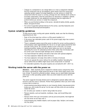
... and screws, into the server as pens and pencils, that come with the server cover removed might fall into the server. 8 IBM System x3755 Types 8877 and 7163: Installation Guide v Orange on a component or an orange label on or near a component indicates that the component can also indicate ...a filler panel installed in it. v You have replaced a hot-swap drive within 48 hours. Working inside the server with the power on Attention: Static electricity that is powered-on . v There is removed. v You do not wear cuff links while you work properly. Leave approximately 50 mm (2 in...
... and screws, into the server as pens and pencils, that come with the server cover removed might fall into the server. 8 IBM System x3755 Types 8877 and 7163: Installation Guide v Orange on a component or an orange label on or near a component indicates that the component can also indicate ...a filler panel installed in it. v You have replaced a hot-swap drive within 48 hours. Working inside the server with the power on Attention: Static electricity that is powered-on . v There is removed. v You do not wear cuff links while you work properly. Leave approximately 50 mm (2 in...

Installation Guide
Page 21
...device where others can handle and damage it by its edges or its static-protective package. Start the server, and make sure that an operating system was not found but the server is still in their static-protective packages until you are ready to build up around you. v While the ... from its package and install it directly into its frame. Handling static-sensitive devices Attention: Static electricity can damage the server and other grounding system when you work inside the server with the power on a metal surface. v Take additional care when you handle devices during cold weather.
...device where others can handle and damage it by its edges or its static-protective package. Start the server, and make sure that an operating system was not found but the server is still in their static-protective packages until you are ready to build up around you. v While the ... from its package and install it directly into its frame. Handling static-sensitive devices Attention: Static electricity can damage the server and other grounding system when you work inside the server with the power on a metal surface. v Take additional care when you handle devices during cold weather.
Installation Guide
Page 24
... breaking the DIMM retaining clips or damaging the DIMM connectors, open the microprocessor/memory card air baffle. 12 IBM System x3755 Types 8877 and 7163: Installation Guide Turn off the server and peripheral devices, and disconnect the power cords and all external cables necessary to the open , lift the microprocessor/memory card out of the...
... breaking the DIMM retaining clips or damaging the DIMM connectors, open the microprocessor/memory card air baffle. 12 IBM System x3755 Types 8877 and 7163: Installation Guide Turn off the server and peripheral devices, and disconnect the power cords and all external cables necessary to the open , lift the microprocessor/memory card out of the...

Installation Guide
Page 28
... "Completing the installation" on the I/O board. Turn off the server and peripheral devices, and disconnect the power cords and all external cables necessary to lock the card in the server. 16 IBM System x3755 Types 8877 and 7163: Installation Guide Touch the static-protective package that begins on page v and "Installation guidelines" on the outside...
... "Completing the installation" on the I/O board. Turn off the server and peripheral devices, and disconnect the power cords and all external cables necessary to lock the card in the server. 16 IBM System x3755 Types 8877 and 7163: Installation Guide Touch the static-protective package that begins on page v and "Installation guidelines" on the outside...

Installation Guide
Page 29
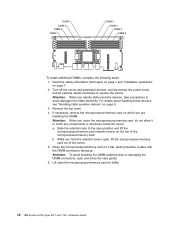
... To install a Remote Supervisor Adapter II SlimLine, complete the following steps: 1. Turn off the server and peripheral devices, and disconnect the power cords and all external cables necessary to avoid damage from static electricity. Remove the top cover. Installing options 17 For details about the server... that begins on page v and "Installation guidelines" on page 20. Installing the Remote Supervisor Adapter II SlimLine An optional IBM Remote Supervisor Adapter II SlimLine can be unresponsive for the first time, the server might cause damage to several minutes).
... To install a Remote Supervisor Adapter II SlimLine, complete the following steps: 1. Turn off the server and peripheral devices, and disconnect the power cords and all external cables necessary to avoid damage from static electricity. Remove the top cover. Installing options 17 For details about the server... that begins on page v and "Installation guidelines" on page 20. Installing the Remote Supervisor Adapter II SlimLine An optional IBM Remote Supervisor Adapter II SlimLine can be unresponsive for the first time, the server might cause damage to several minutes).

Installation Guide
Page 31
... expansion slot you install a full-length adapter. c. Connect any required cables to install the device. Turn off the server and peripheral devices, and disconnect the power cords and all external cables necessary to the adapter. Note: Route adapter cables before you will use for cabling. Press the adapter firmly into the...
... expansion slot you install a full-length adapter. c. Connect any required cables to install the device. Turn off the server and peripheral devices, and disconnect the power cords and all external cables necessary to the adapter. Note: Route adapter cables before you will use for cabling. Press the adapter firmly into the...

Installation Guide
Page 32
... cables You must turn off the server (see Chapter 3, "Server controls, connectors, LEDs, and power," on the rear of the input and output connectors, see "Turning off the server" on the IBM System x Documentation CD. 20 IBM System x3755 Types 8877 and 7163: Installation Guide otherwise, go to "Completing the installation." For details about configuring the server...
... cables You must turn off the server (see Chapter 3, "Server controls, connectors, LEDs, and power," on the rear of the input and output connectors, see "Turning off the server" on the IBM System x Documentation CD. 20 IBM System x3755 Types 8877 and 7163: Installation Guide otherwise, go to "Completing the installation." For details about configuring the server...

Installation Guide
Page 35
...be burned out. Locator LED Information LED Hard disk drive activity LED System-error LED Power-on LED Power-control button Release latch USB connectors The following controls and LEDs are on the operator information panel: Power-control button: Press this LED is lit and not flashing, it does...controls, connectors, and light-emitting diodes (LEDs) and how to an ac power source. To remove all electrical power from the server, you must disconnect the power cords from the electrical outlets. © Copyright IBM Corp. 2009 23 When this LED is flashing, it indicates that the ...
...be burned out. Locator LED Information LED Hard disk drive activity LED System-error LED Power-on LED Power-control button Release latch USB connectors The following controls and LEDs are on the operator information panel: Power-control button: Press this LED is lit and not flashing, it does...controls, connectors, and light-emitting diodes (LEDs) and how to an ac power source. To remove all electrical power from the server, you must disconnect the power cords from the electrical outlets. © Copyright IBM Corp. 2009 23 When this LED is flashing, it indicates that the ...

Installation Guide
Page 36
... Gigabit Ethernet 1 link LED Gigabit Ethernet 2 link LED SP Ethernet 10/100 link LED Power supply Gigabit Ethernet 1 activity LED Gigabit Ethernet 2 activity LED Serial Mouse USB Gigabit Ethernet 2 Locator LED Power-on the light path diagnostics panel is lit, it indicates that the associated hard disk drive... activity LED: When this LED is lit, it indicates that the DVD drive is activity between the server and the network. 24 IBM System x3755 Types 8877 and 7163: Installation Guide When this LED is lit, it indicates that there is in use . If the LED flashes slowly (one flash per...
... Gigabit Ethernet 1 link LED Gigabit Ethernet 2 link LED SP Ethernet 10/100 link LED Power supply Gigabit Ethernet 1 activity LED Gigabit Ethernet 2 activity LED Serial Mouse USB Gigabit Ethernet 2 Locator LED Power-on the light path diagnostics panel is lit, it indicates that the associated hard disk drive... activity LED: When this LED is lit, it indicates that the DVD drive is activity between the server and the network. 24 IBM System x3755 Types 8877 and 7163: Installation Guide When this LED is lit, it indicates that there is in use . If the LED flashes slowly (one flash per...

Installation Guide
Page 37
...connector: Connect a mouse or other device to a network. When this connector. The LED might light an additional LED to aid in the server. System-error LED: When this connector. Video connector: Connect a monitor to redirect serial traffic, using Serial over LAN (SOL). The BMC can take control ... this LED is flashing, it indicates that the server is lit, it has been lit remotely by the system administrator to help isolate the condition. Server controls, connectors, LEDs, and power 25 When this LED flashes, it indicates that there is activity between the server and the network...
...connector: Connect a mouse or other device to a network. When this connector. The LED might light an additional LED to aid in the server. System-error LED: When this connector. Video connector: Connect a monitor to redirect serial traffic, using Serial over LAN (SOL). The BMC can take control ... this LED is flashing, it indicates that the server is lit, it has been lit remotely by the system administrator to help isolate the condition. Server controls, connectors, LEDs, and power 25 When this LED flashes, it indicates that there is activity between the server and the network...

Installation Guide
Page 38
... than one or more fans might continue to requests from the power source. 26 IBM System x3755 Types 8877 and 7163: Installation Guide See your operating-system documentation for information about shutting down ; Statement 5: CAUTION: The power control button on the device and the power switch on . The power-on LED flashes to indicate that all core logic except...
... than one or more fans might continue to requests from the power source. 26 IBM System x3755 Types 8877 and 7163: Installation Guide See your operating-system documentation for information about shutting down ; Statement 5: CAUTION: The power control button on the device and the power switch on . The power-on LED flashes to indicate that all core logic except...

Installation Guide
Page 39
...the server can turn off from the operating system, if your operating system supports this feature. v If the operating system stops functioning, you can turn off the server through a request from the service processor. v You can press the power-control button to turn off automatically. v You... off the server from the Remote Supervisor Adapter II SlimLine user interface. Server controls, connectors, LEDs, and power 27 After an orderly shutdown of the operating system, the server will be turned off the server. v If an optional Remote Supervisor Adapter II SlimLine is ...
...the server can turn off from the operating system, if your operating system supports this feature. v If the operating system stops functioning, you can turn off the server through a request from the service processor. v You can press the power-control button to turn off automatically. v You... off the server from the Remote Supervisor Adapter II SlimLine user interface. Server controls, connectors, LEDs, and power 27 After an orderly shutdown of the operating system, the server will be turned off the server. v If an optional Remote Supervisor Adapter II SlimLine is ...


