User Guide
Page 5
... a rack 73 © Copyright IBM Corp. 2008 iii Contents Safety v Chapter 1. Installing options 17 Server components 17 System-board internal connectors 18 System-board switches 19 System-board external connectors 20 System-board option connectors 21 System-board LEDs 22 Installation guidelines 22 System reliability guidelines 23 Working inside the server with the power on 23 Handling static...
... a rack 73 © Copyright IBM Corp. 2008 iii Contents Safety v Chapter 1. Installing options 17 Server components 17 System-board internal connectors 18 System-board switches 19 System-board external connectors 20 System-board option connectors 21 System-board LEDs 22 Installation guidelines 22 System reliability guidelines 23 Working inside the server with the power on 23 Handling static...
User Guide
Page 31
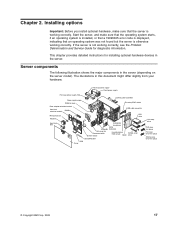
..., make sure that the operating system starts, if an operating system is installed, or that a 19990305 error code is displayed, indicating that the server is working correctly. Hot-swap power supply Fixed power supply Hot-swap power supply filler Power supply cage DIMM air duct Rear adapter retention...swap drive trim piece © Copyright IBM Corp. 2008 17 This chapter provides detailed instructions for diagnostic information. If the server is otherwise working correctly. Chapter 2. Start the server, and make sure that an operating system was not found but the server is ...
..., make sure that the operating system starts, if an operating system is installed, or that a 19990305 error code is displayed, indicating that the server is working correctly. Hot-swap power supply Fixed power supply Hot-swap power supply filler Power supply cage DIMM air duct Rear adapter retention...swap drive trim piece © Copyright IBM Corp. 2008 17 This chapter provides detailed instructions for diagnostic information. If the server is otherwise working correctly. Chapter 2. Start the server, and make sure that an operating system was not found but the server is ...
User Guide
Page 41
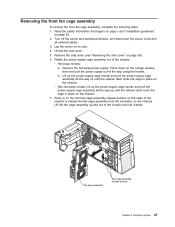
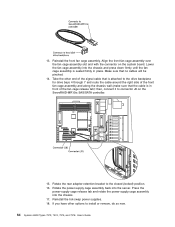
... the way up and out of the chassis and set it aside. b. Lift up the power-supply cage handle and pull the power-supply cage assembly all the way up until the retainer latch locks the cage in place on its side. 4. Remove the side cover (see "Removing the side cover".... 5. Press down on the chassis. v Non-hot-swap models, lift up the power-supply cage handle and pull the power-supply cage assembly all external cables. 3. Lay the server on the chassis. 7. Rotate the power-supply cage assembly out of the bay, using the handle. Read the safety information that begins on...
... the way up and out of the chassis and set it aside. b. Lift up the power-supply cage handle and pull the power-supply cage assembly all the way up until the retainer latch locks the cage in place on its side. 4. Remove the side cover (see "Removing the side cover".... 5. Press down on the chassis. v Non-hot-swap models, lift up the power-supply cage handle and pull the power-supply cage assembly all external cables. 3. Lay the server on the chassis. 7. Rotate the power-supply cage assembly out of the bay, using the handle. Read the safety information that begins on...
User Guide
Page 45
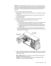
.... 4. Press down on page 22. 2. Locate the DIMM connectors on might cause the server to internal server components when the server is powered-on the system board. Rotate the power-supply cage assembly out of the chassis: v Hot-swap models: a. Attention: Static electricity that begins on page v and "Installation guidelines" on the orange release...
.... 4. Press down on page 22. 2. Locate the DIMM connectors on might cause the server to internal server components when the server is powered-on the system board. Rotate the power-supply cage assembly out of the chassis: v Hot-swap models: a. Attention: Static electricity that begins on page v and "Installation guidelines" on the orange release...
User Guide
Page 47
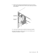
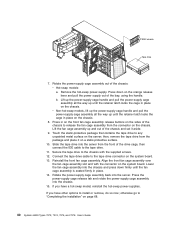
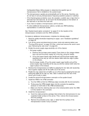
Press the power-supply cage release tab and rotate the power-supply cage assembly into the server. If you have other options to "Completing the installation" on page 68. Installing options 33 If you have a hot-swap model, reinstall the hot-swap power-supplies. otherwise, go to install or remove, do so now; Power supply support bracket Power supply release tab 12. Rotate the power-supply cage assembly back into the chassis. 11. Chapter 2.
Press the power-supply cage release tab and rotate the power-supply cage assembly into the server. If you have other options to "Completing the installation" on page 68. Installing options 33 If you have a hot-swap model, reinstall the hot-swap power-supplies. otherwise, go to install or remove, do so now; Power supply support bracket Power supply release tab 12. Rotate the power-supply cage assembly back into the chassis. 11. Chapter 2.
User Guide
Page 51
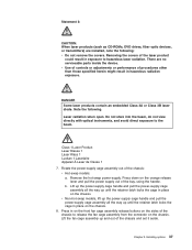
...procedures other than those specified herein might result in exposure to the beam. v Non-hot-swap models, lift up the power-supply cage handle and pull the power-supply cage assembly all the way up and out of the laser product could result in hazardous radiation exposure. Do not stare into ...the chassis and set it aside. Remove the hot-swap power-supply. Lift the fan cage assembly up until the retainer latch locks the cage in place on the chassis. 8. Lift up the power-supply cage handle and pull the power-supply cage assembly all the way up until the retainer latch locks the...
...procedures other than those specified herein might result in exposure to the beam. v Non-hot-swap models, lift up the power-supply cage handle and pull the power-supply cage assembly all the way up and out of the laser product could result in hazardous radiation exposure. Do not stare into ...the chassis and set it aside. Remove the hot-swap power-supply. Lift the fan cage assembly up until the retainer latch locks the cage in place on the chassis. 8. Lift up the power-supply cage handle and pull the power-supply cage assembly all the way up until the retainer latch locks the...
User Guide
Page 52
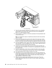
then, remove the drive from the front and then attach the cables. 11. Reinstall the front fan cage assembly. Rotate the power-supply cage assembly back into the chassis. 38 System x3400 Types 7973, 7974, 7975, and 7976: User's Guide drive in place. 17. Connect one end of the signal cable to the rear ...of the drive and make sure that the other end of the drives or over the fan cage assembly ...
then, remove the drive from the front and then attach the cables. 11. Reinstall the front fan cage assembly. Rotate the power-supply cage assembly back into the chassis. 38 System x3400 Types 7973, 7974, 7975, and 7976: User's Guide drive in place. 17. Connect one end of the signal cable to the rear ...of the drive and make sure that the other end of the drives or over the fan cage assembly ...
User Guide
Page 54
... page 68. 40 System x3400 Types 7973, 7974, 7975, and 7976: User's Guide Align the front fan cage assembly over the fan cage assembly slot and with the supplied screws. 12. Rotate the power-supply cage assembly out of the bay, using the handle. Lift up the power-supply cage handle and pull the power-supply cage assembly all the way...
... page 68. 40 System x3400 Types 7973, 7974, 7975, and 7976: User's Guide Align the front fan cage assembly over the fan cage assembly slot and with the supplied screws. 12. Rotate the power-supply cage assembly out of the bay, using the handle. Lift up the power-supply cage handle and pull the power-supply cage assembly all the way...
User Guide
Page 63
...your IBM marketing representative or authorized reseller. Read the safety information beginning on page v, and "Installation guidelines" on the orange release lever and pull the power supply out of the bay, using the handle. Lift up the power-supply cage handle and pull the power-supply cage assembly all power cords...the server. 5. v Non-hot-swap models, lift up the power-supply cage handle and pull the power-supply cage assembly all the way up until the retainer latch locks the cage in the connector. 8. b. Rotate the rear system fan air baffle up out of the way by grasping the ...
...your IBM marketing representative or authorized reseller. Read the safety information beginning on page v, and "Installation guidelines" on the orange release lever and pull the power supply out of the bay, using the handle. Lift up the power-supply cage handle and pull the power-supply cage assembly all power cords...the server. 5. v Non-hot-swap models, lift up the power-supply cage handle and pull the power-supply cage assembly all the way up until the retainer latch locks the cage in the connector. 8. b. Rotate the rear system fan air baffle up out of the way by grasping the ...
User Guide
Page 66
...any part that you have other information that has the following precautions. When you have hot-swap power supplies. Press down firmly on page 68. Rotate the power-supply cage assembly back into the chassis. 13. Otherwise, go to redundant mode. v This procedure applies ... inside these parts, contact a service technician. 52 System x3400 Types 7973, 7974, 7975, and 7976: User's Guide v The redundant mode requires two 835-watt hot-swap power supplies in the server. Statement 8: CAUTION: Never remove the cover on a power supply or any component that have a hot-swap ...
...any part that you have other information that has the following precautions. When you have hot-swap power supplies. Press down firmly on page 68. Rotate the power-supply cage assembly back into the chassis. 13. Otherwise, go to redundant mode. v This procedure applies ... inside these parts, contact a service technician. 52 System x3400 Types 7973, 7974, 7975, and 7976: User's Guide v The redundant mode requires two 835-watt hot-swap power supplies in the server. Statement 8: CAUTION: Never remove the cover on a power supply or any component that have a hot-swap ...

User Guide
Page 69
... working inside the server with the power on page 68. Attention: To ensure proper system cooling, do so now; Remove the side cover (see "Removing the side cover" on the rear of the fan cage assembly. Make sure that both the ac and dc power LEDs on page 26). 9. Grasp the fan handle and... pull the fan out of the power supply are supplied to...
... working inside the server with the power on page 68. Attention: To ensure proper system cooling, do so now; Remove the side cover (see "Removing the side cover" on the rear of the fan cage assembly. Make sure that both the ac and dc power LEDs on page 26). 9. Grasp the fan handle and... pull the fan out of the power supply are supplied to...
User Guide
Page 76
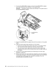
... connector on the ServeRAID-MR10is SAS/SATA controller. 62 System x3400 Types 7973, 7974, 7975, and 7976: User's Guide Rotate the power-supply cage assembly out of the bay, using the handle. Remove the hot-swap power-supply. Lift up the power-supply cage handle and pull the power-supply cage assembly all the way up until the retainer latch...
... connector on the ServeRAID-MR10is SAS/SATA controller. 62 System x3400 Types 7973, 7974, 7975, and 7976: User's Guide Rotate the power-supply cage assembly out of the bay, using the handle. Remove the hot-swap power-supply. Lift up the power-supply cage handle and pull the power-supply cage assembly all the way up until the retainer latch...
User Guide
Page 78
... into the server. Take the other options to install or remove, do so now. 64 System x3400 Types 7973, 7974, 7975, and 7976: User's Guide Rotate the power-supply cage assembly back into the chassis. 17. If you have other end of the signal cable that is attached to the drive ...the closed (locked) position. 16. Reinstall the hot-swap power supplies. 18. Reinstall the front fan cage assembly. Rotate the rear adapter-retention bracket to connector J8 on the system board. Align the front fan cage assembly over the fan cage assembly slot and with the connector on the ServeRAID-MR10is SAS...
... into the server. Take the other options to install or remove, do so now. 64 System x3400 Types 7973, 7974, 7975, and 7976: User's Guide Rotate the power-supply cage assembly back into the chassis. 17. If you have other end of the signal cable that is attached to the drive ...the closed (locked) position. 16. Reinstall the hot-swap power supplies. 18. Reinstall the front fan cage assembly. Rotate the rear adapter-retention bracket to connector J8 on the system board. Align the front fan cage assembly over the fan cage assembly slot and with the connector on the ServeRAID-MR10is SAS...
Installation Guide
Page 5
...7975 and 7976 features and specifications 6 Major components of the server 8 Chapter 2. Server controls, LEDs, and power 37 Front view 37 Rear view 40 Server power features 42 Turning on 10 Handling static-sensitive devices 11 Removing the side cover 12 Removing the bezel 13 Removing the front fan cage...utility programs 63 Using the Boot Menu program 64 © Copyright IBM Corp. 2008 iii Installing options 9 Installation guidelines 9 System reliability guidelines 10 Working inside the server with the power on the server 42 Turning off the server 42 Chapter 4. Contents...
...7975 and 7976 features and specifications 6 Major components of the server 8 Chapter 2. Server controls, LEDs, and power 37 Front view 37 Rear view 40 Server power features 42 Turning on 10 Handling static-sensitive devices 11 Removing the side cover 12 Removing the bezel 13 Removing the front fan cage...utility programs 63 Using the Boot Menu program 64 © Copyright IBM Corp. 2008 iii Installing options 9 Installation guidelines 9 System reliability guidelines 10 Working inside the server with the power on the server 42 Turning off the server 42 Chapter 4. Contents...
Installation Guide
Page 22
.... (Orange can grip the component to perform before you remove or install the component. Hot-swap power supply Fixed power supply Hot-swap power supply filler Power supply cage DIMM air duct Rear adapter retention bracket Heat sink retention bracket DIMMs Microprocessor Heatsink Control panel assembly Drive...Hot-swap fan Processor baffle System board Hard disk drive EMC shield Bezel Simple-swap drive ServeRAID 8k-1 VRM Cover Hot-swap drive DVD drive trim piece Hot-swap drive trim piece Simple-swap drive trim piece 8 System x3400 Types 7973, 7974, 7975, and 7976: Installation Guide...
.... (Orange can grip the component to perform before you remove or install the component. Hot-swap power supply Fixed power supply Hot-swap power supply filler Power supply cage DIMM air duct Rear adapter retention bracket Heat sink retention bracket DIMMs Microprocessor Heatsink Control panel assembly Drive...Hot-swap fan Processor baffle System board Hard disk drive EMC shield Bezel Simple-swap drive ServeRAID 8k-1 VRM Cover Hot-swap drive DVD drive trim piece Hot-swap drive trim piece Simple-swap drive trim piece 8 System x3400 Types 7973, 7974, 7975, and 7976: Installation Guide...

Installation Guide
Page 29
...aside. Lift up the power-supply cage handle and pull the power-supply cage assembly all the way up until the retainer latch locks the cage in place on the chassis. 5. Remove the side cover (see "Removing the side cover" on the chassis. Fan cage assembly Fan cage assembly release buttons Chapter... 2. Press in place on the chassis. Removing the front fan cage assembly To remove the front fan cage assembly, complete the following steps: 1. v Non-hot-swap models, lift up the power-supply cage handle and pull the power-supply cage assembly all the way up and out of the chassis: v...
...aside. Lift up the power-supply cage handle and pull the power-supply cage assembly all the way up until the retainer latch locks the cage in place on the chassis. 5. Remove the side cover (see "Removing the side cover" on the chassis. Fan cage assembly Fan cage assembly release buttons Chapter... 2. Press in place on the chassis. Removing the front fan cage assembly To remove the front fan cage assembly, complete the following steps: 1. v Non-hot-swap models, lift up the power-supply cage handle and pull the power-supply cage assembly all the way up and out of the chassis: v...
Installation Guide
Page 33
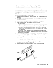
... cage assembly out of data. Do not install DIMMs in this potential problem, always use an electrostatic-discharge wrist strap or other grounding system when working inside the server with the power on page 12). 4. Installing options 19 Read the ...safety information that the memory configuration has changed. Locate the DIMM connectors on page 9. 2. Remove the hot-swap power-supply. v Non-hot-swap models, lift up the power-supply cage handle and pull the power-supply cage...
... cage assembly out of data. Do not install DIMMs in this potential problem, always use an electrostatic-discharge wrist strap or other grounding system when working inside the server with the power on page 12). 4. Installing options 19 Read the ...safety information that the memory configuration has changed. Locate the DIMM connectors on page 9. 2. Remove the hot-swap power-supply. v Non-hot-swap models, lift up the power-supply cage handle and pull the power-supply cage...

Installation Guide
Page 34
... on the server. DIMM 6 DIMM 5 DIMM4 DIMM3 DIMM 2 DIMM 1 DIMM 12 DIMM11 DIMM 10 DIMM 9 DIMM 8 DIMM 7 10. Rotate the power-supply cage assembly back into the chassis. 20 System x3400 Types 7973, 7974, 7975, and 7976: Installation Guide The retaining clips snap into the connector by aligning the edges of the DIMM connector. Then...
... on the server. DIMM 6 DIMM 5 DIMM4 DIMM3 DIMM 2 DIMM 1 DIMM 12 DIMM11 DIMM 10 DIMM 9 DIMM 8 DIMM 7 10. Rotate the power-supply cage assembly back into the chassis. 20 System x3400 Types 7973, 7974, 7975, and 7976: Installation Guide The retaining clips snap into the connector by aligning the edges of the DIMM connector. Then...


