User Guide
Page 25
...IBM System x3400 Documentation CD. USB connectors Connect USB devices to help isolate the error. Hard disk drive activity LED When this LED is not present, or the power supply or the LED itself has failed. When this LED is lit, it indicates that the system is in the Problem Determination and Service Guide on . Power-control button... Press this button to ac power. System power LED Power-control button Hard disk drive activity LED System error LED Front information panel ...
...IBM System x3400 Documentation CD. USB connectors Connect USB devices to help isolate the error. Hard disk drive activity LED When this LED is not present, or the power supply or the LED itself has failed. When this LED is lit, it indicates that the system is in the Problem Determination and Service Guide on . Power-control button... Press this button to ac power. System power LED Power-control button Hard disk drive activity LED System error LED Front information panel ...
Installation Guide
Page 53
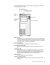
... disk drive activity LED. If the LED flashes rapidly (three flashes per second), the drive is being rebuilt. Chapter 3. CD or DVD eject button Press this button to these connectors. USB connectors Connect USB devices to release a CD from the CD drive or a DVD from the DVD drive. See Chapter ... to help isolate the error. Server controls, LEDs, and power 39 An LED on the IBM Documentation CD. The backplane is in the Problem Determination and Service Guide on the system board might also be lit to the drive connector. System-error LED When this amber LED is lit, it indicates ...
... disk drive activity LED. If the LED flashes rapidly (three flashes per second), the drive is being rebuilt. Chapter 3. CD or DVD eject button Press this button to these connectors. USB connectors Connect USB devices to release a CD from the CD drive or a DVD from the DVD drive. See Chapter ... to help isolate the error. Server controls, LEDs, and power 39 An LED on the IBM Documentation CD. The backplane is in the Problem Determination and Service Guide on the system board might also be lit to the drive connector. System-error LED When this amber LED is lit, it indicates ...

Installation Guide
Page 55
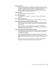
... the Problem Determination and Service Guide on the rear of LEDs, see the Problem Determination and Service Guide on the IBM System x3400 Documentation CD. Keyboard connector Connect a PS/2 keyboard to this connector. During typical operation, both the ac and dc power LEDs ...Adapter II SlimLine) NMI button Serial 2 (COM 2) Power-cord connector Connect the power cord to this connector. Mouse connector Connect a mouse device to this connector. Server controls, LEDs, and power 41 The following illustration shows the connectors on the IBM System x3400 Documentation CD. Parallel ...
... the Problem Determination and Service Guide on the rear of LEDs, see the Problem Determination and Service Guide on the IBM System x3400 Documentation CD. Keyboard connector Connect a PS/2 keyboard to this connector. During typical operation, both the ac and dc power LEDs ...Adapter II SlimLine) NMI button Serial 2 (COM 2) Power-cord connector Connect the power cord to this connector. Mouse connector Connect a mouse device to this connector. Server controls, LEDs, and power 41 The following illustration shows the connectors on the IBM System x3400 Documentation CD. Parallel ...
Installation Guide
Page 102
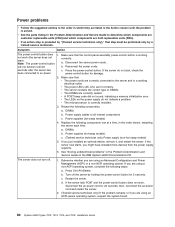
... you are using an ACPI-aware operating system, suspect the system board. 88 System x3400 Types 7973, 7974, 7975, and 7976: Installation Guide v If an action step is preceded by "(Trained service technician only)," that the control-panel assembly power-control button is correctly installed. 3. Reconnect the power cords. Disconnect the server power cords. Turn off . 1. Make sure that...
... you are using an ACPI-aware operating system, suspect the system board. 88 System x3400 Types 7973, 7974, 7975, and 7976: Installation Guide v If an action step is preceded by "(Trained service technician only)," that the control-panel assembly power-control button is correctly installed. 3. Reconnect the power cords. Disconnect the server power cords. Turn off . 1. Make sure that...

Installation Guide
Page 117
... drives 28 simple-swap SATA drives 27 caution statements 4 CD drive activity LED 39 eject button 39 installing 21 problems 80 specifications 5, 6 Class A electronic emission notice 99 © Copyright IBM Corp. 2008 command-line interface commands identify 63 power 63 sel 63 sysinfo 63 for remote management 63 components, major 8 configuration Configuration/Setup Utility...
... drives 28 simple-swap SATA drives 27 caution statements 4 CD drive activity LED 39 eject button 39 installing 21 problems 80 specifications 5, 6 Class A electronic emission notice 99 © Copyright IBM Corp. 2008 command-line interface commands identify 63 power 63 sel 63 sysinfo 63 for remote management 63 components, major 8 configuration Configuration/Setup Utility...
Installation Guide
Page 118
... 19 retaining clips 20 DVD drive activity LED 39 eject button 39 problems 80 Ethernet activity LED 42 connector 42 controller, configuring 65 high performance modes 65 integrated on system board 65 link status LED 42 modes 65 example memory ...memory 84 microprocessor 84 mouse 83 mouse, USB 90 optional devices 87 pointing device 83 pointing device, USB 90 power 88 serial port 89 software 90 USB port 83, 90 G getting help 93 H handling static-sensitive devices...swap SAS drives cabling 28 hot-swap SATA drives cabling 28 104 System x3400 Types 7973, 7974, 7975, and 7976: Installation Guide
... 19 retaining clips 20 DVD drive activity LED 39 eject button 39 problems 80 Ethernet activity LED 42 connector 42 controller, configuring 65 high performance modes 65 integrated on system board 65 link status LED 42 modes 65 example memory ...memory 84 microprocessor 84 mouse 83 mouse, USB 90 optional devices 87 pointing device 83 pointing device, USB 90 power 88 serial port 89 software 90 USB port 83, 90 G getting help 93 H handling static-sensitive devices...swap SAS drives cabling 28 hot-swap SATA drives cabling 28 104 System x3400 Types 7973, 7974, 7975, and 7976: Installation Guide
Installation Guide
Page 119
...IBM Director 65 IBM... problems 82 internal drives, installing 21 K keyboard connector 41 keyboard problems ...power-on 38 system-error 39 M Machine Types 7973 and 7974 features and specifications 5 Machine Types 7975 and 7976 features and specifications 6 major components 8 memory configuration 85 memory (continued) installing 16 problems...problems 84 specifications 5, 6, 7 mirrored mode memory installation sequence 17 modes, Ethernet 65 mouse connector 41 mouse problems... optional device installation guidelines 9 problems 87 static-sensitive 11 options adapters...problems 83, 90 ports Ethernet 42 parallel 41 ...
...IBM Director 65 IBM... problems 82 internal drives, installing 21 K keyboard connector 41 keyboard problems ...power-on 38 system-error 39 M Machine Types 7973 and 7974 features and specifications 5 Machine Types 7975 and 7976 features and specifications 6 major components 8 memory configuration 85 memory (continued) installing 16 problems...problems 84 specifications 5, 6, 7 mirrored mode memory installation sequence 17 modes, Ethernet 65 mouse connector 41 mouse problems... optional device installation guidelines 9 problems 87 static-sensitive 11 options adapters...problems 83, 90 ports Ethernet 42 parallel 41 ...


