
Installation Guide
Page 5
...the installation 17 Replacing the server cover 17 Connecting the cables 18 Updating the server configuration 19 Chapter 3. Contents Safety v Chapter 1. Installing optional devices 7 Installation guidelines 7 System reliability guidelines 8 Working inside the server with the power on the server 24 Turning off the server 24 Chapter 4. Configuring the server 27 Using the ServerGuide Setup and Installation CD 27 Using the Configuration/Setup Utility program 28 Using the LSI Logic Configuration Utility program 28 Using the baseboard management controller 29 Using the Boot Menu...
...the installation 17 Replacing the server cover 17 Connecting the cables 18 Updating the server configuration 19 Chapter 3. Contents Safety v Chapter 1. Installing optional devices 7 Installation guidelines 7 System reliability guidelines 8 Working inside the server with the power on the server 24 Turning off the server 24 Chapter 4. Configuring the server 27 Using the ServerGuide Setup and Installation CD 27 Using the Configuration/Setup Utility program 28 Using the LSI Logic Configuration Utility program 28 Using the baseboard management controller 29 Using the Boot Menu...
Installation Guide
Page 21
... have been left inside the server with setting up IBM server hardware. Go to download and apply the most recent firmware updates. If you install optional devices, read the following information: v Read the safety information that your server is too heavy for diagnostic information. Start the server, and make sure that no tools or other objects have to disk drives. Note: Changes are working correctly. Under Product support, click System x. 3. Click System x3350 to function...
... have been left inside the server with setting up IBM server hardware. Go to download and apply the most recent firmware updates. If you install optional devices, read the following information: v Read the safety information that your server is too heavy for diagnostic information. Start the server, and make sure that no tools or other objects have to disk drives. Note: Changes are working correctly. Under Product support, click System x. 3. Click System x3350 to function...
Installation Guide
Page 25
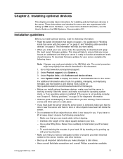
... server cover off the server and set the cover aside. Locate the documentation that comes with the hard disk drive and follow those instructions in addition to the instructions in these servers. The following steps. Chapter 2. Installing optional devices 11 Attention: For proper cooling and airflow, replace the server cover before you have the same throughput speed rating. For a list of the following hard disk drive configurations: v Do not use both SAS and SATA drives in these servers...
... server cover off the server and set the cover aside. Locate the documentation that comes with the hard disk drive and follow those instructions in addition to the instructions in these servers. The following steps. Chapter 2. Installing optional devices 11 Attention: For proper cooling and airflow, replace the server cover before you have the same throughput speed rating. For a list of the following hard disk drive configurations: v Do not use both SAS and SATA drives in these servers...
Installation Guide
Page 27
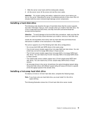
... switch settings or jumper settings on the adapter, follow the instructions that come with the adapter and follow those instructions in this section. If the server has a RAID controller or adapter, you have other and slide the drive into the drive bay to the instructions in addition to cover the drive. If you might have not changed the default startup sequence: PCI Express slot 1, then PCI Express slot 2. Remove the filler panel from the Configuration/Setup Utility program main menu...
... switch settings or jumper settings on the adapter, follow the instructions that come with the adapter and follow those instructions in this section. If the server has a RAID controller or adapter, you have other and slide the drive into the drive bay to the instructions in addition to cover the drive. If you might have not changed the default startup sequence: PCI Express slot 1, then PCI Express slot 2. Remove the filler panel from the Configuration/Setup Utility program main menu...

Installation Guide
Page 33
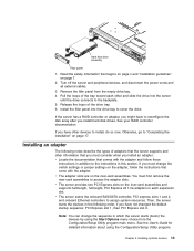
... the cable. If the server has an optional RAID adapter and you must install. Updating the server configuration When you start the server for the first time after you add or remove a device, you can save the new configuration settings. Installing optional devices 19 For information about reconfiguring the disk arrays. Ethernet cable release lever Ethernet Cable Release Tab Note: There are release levers on the lever to manage the server remotely, see the Remote Supervisor Adapter ll SlimLine User's Guide, which...
... the cable. If the server has an optional RAID adapter and you must install. Updating the server configuration When you start the server for the first time after you add or remove a device, you can save the new configuration settings. Installing optional devices 19 For information about reconfiguring the disk arrays. Ethernet cable release lever Ethernet Cable Release Tab Note: There are release levers on the lever to manage the server remotely, see the Remote Supervisor Adapter ll SlimLine User's Guide, which...

Installation Guide
Page 36
.../DVD drive is turned on. To remove all electrical power from the server, you must disconnect the power cord from the rack. System locator LED: Use this LED is off, it indicates that a system error has occurred. System-error LED: When this LED is off and is controlled by the BMC. - See the Problem Determination and Service Guide for more information about error logs. - See the information about light path diagnostics in the server. v USB connectors: Connect a USB device, such as a USB mouse, keyboard...
.../DVD drive is turned on. To remove all electrical power from the server, you must disconnect the power cord from the rack. System locator LED: Use this LED is off, it indicates that a system error has occurred. System-error LED: When this LED is off and is controlled by the BMC. - See the Problem Determination and Service Guide for more information about error logs. - See the information about light path diagnostics in the server. v USB connectors: Connect a USB device, such as a USB mouse, keyboard...

Installation Guide
Page 37
... and rear of LEDs, see the Problem Determination and Service Guide on . The video connectors on LED connector System-locator LED System-error LED Systemsmanagement Ethernet connector Serial connector DC power LED v PCI slots 1 and 2: Connect the PCI Express adapters to the system. Chapter 3. For any other device to any other servers. v System-error LED: When this LED is lit and not flashing, it indicates that the power supply is shared with the baseboard management controller (BMC). When the ac power LED is lit, it indicates that ac power is turned off...
... and rear of LEDs, see the Problem Determination and Service Guide on . The video connectors on LED connector System-locator LED System-error LED Systemsmanagement Ethernet connector Serial connector DC power LED v PCI slots 1 and 2: Connect the PCI Express adapters to the system. Chapter 3. For any other device to any other servers. v System-error LED: When this LED is lit and not flashing, it indicates that the power supply is shared with the baseboard management controller (BMC). When the ac power LED is lit, it indicates that ac power is turned off...
Installation Guide
Page 52
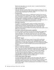
... the problem is not working . 2. A hard disk drive was not detected while the operating system was being started. v See the parts listing in the Problem Determination and Service Guide on the IBM System x Documentation CD to determine which components are customer replaceable units (CRU) and which components are field replaceable units (FRU). Symptom Action Not all hard disk drives and cables; The server stops responding during the hard disk drive diagnostic test. If the hard disk drive diagnostic test runs successfully, replace the drive that...
... the problem is not working . 2. A hard disk drive was not detected while the operating system was being started. v See the parts listing in the Problem Determination and Service Guide on the IBM System x Documentation CD to determine which components are customer replaceable units (CRU) and which components are field replaceable units (FRU). Symptom Action Not all hard disk drives and cables; The server stops responding during the hard disk drive diagnostic test. If the hard disk drive diagnostic test runs successfully, replace the drive that...
Installation Guide
Page 64
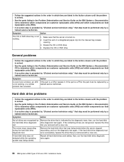
... A USB device does not work. 1. Make sure that the USB configuration options are set correctly in the Configuration/Setup Utility program (see the User's Guide for more information). 3. Make sure that : v The correct USB device driver is a system of LEDs on the light path diagnostics panel. 50 IBM System x3350 Types 4192 and 4193: Installation Guide Light path diagnostics Light path diagnostics is installed. The server is designed so that LEDs remain lit when the server is connected to a power source but not take immediate action, press the remind button...
... A USB device does not work. 1. Make sure that the USB configuration options are set correctly in the Configuration/Setup Utility program (see the User's Guide for more information). 3. Make sure that : v The correct USB device driver is a system of LEDs on the light path diagnostics panel. 50 IBM System x3350 Types 4192 and 4193: Installation Guide Light path diagnostics Light path diagnostics is installed. The server is designed so that LEDs remain lit when the server is connected to a power source but not take immediate action, press the remind button...

Installation Guide
Page 79
... or SATA hard disk drives 28 simple-swap SATA hard disk drives 28 the server 27 connector Ethernet 24 Ethernet systems-management 23 power supply 23 connector (continued) serial 23 USB 22, 23 video front 22 rear 23 connectors location, front view 21 rear view 23 controllers Ethernet 30 cooling 8 cover removing 9 D danger statements 3 dc power LED 23 diagnostic tools 33 DIMMs installing 15 diskette drive specifications 3 display problems 42 documentation Documentation Browser 2 Documentation CD 2 updating 1 dual inline memory module (DIMM) connectors 15 retaining clips 16 DVD drive problems 37...
... or SATA hard disk drives 28 simple-swap SATA hard disk drives 28 the server 27 connector Ethernet 24 Ethernet systems-management 23 power supply 23 connector (continued) serial 23 USB 22, 23 video front 22 rear 23 connectors location, front view 21 rear view 23 controllers Ethernet 30 cooling 8 cover removing 9 D danger statements 3 dc power LED 23 diagnostic tools 33 DIMMs installing 15 diskette drive specifications 3 display problems 42 documentation Documentation Browser 2 Documentation CD 2 updating 1 dual inline memory module (DIMM) connectors 15 retaining clips 16 DVD drive problems 37...

Installation Guide
Page 80
error symptoms (continued) USB port 50 Ethernet link status LED 24 systems-management connector 23 Ethernet activity LED 24 Ethernet connector 24 Ethernet controllers 30 expansion bays 4 F fans 4 FCC Class A notice 62 features server 3 firmware updating 1 front cables, connecting 18 G getting help 55 gloss statement (Germany) 62 H handling static-sensitive devices 9 hard disk drive installing 11 problems 38 hard disk drive activity LED 22 hard disk drive status LED 22 hard drive activity LED 22 hardware configuration 27 requirements 2 hardware service and support 56 heat output 3, 4 help, ...
error symptoms (continued) USB port 50 Ethernet link status LED 24 systems-management connector 23 Ethernet activity LED 24 Ethernet connector 24 Ethernet controllers 30 expansion bays 4 F fans 4 FCC Class A notice 62 features server 3 firmware updating 1 front cables, connecting 18 G getting help 55 gloss statement (Germany) 62 H handling static-sensitive devices 9 hard disk drive installing 11 problems 38 hard disk drive activity LED 22 hard disk drive status LED 22 hard drive activity LED 22 hardware configuration 27 requirements 2 hardware service and support 56 heat output 3, 4 help, ...
User Guide
Page 20
... IBM Director documentation on the server support TOE, which provide redundancy and hot-swap capability for information about light path diagnostics in addition to specific software application programs and hardware systems-management interface, and view them using IBM Director. v Redundant connection The addition of an optional network interface card (NIC) provides failover capability to create RAID configurations. If a problem occurs with the server, you can add, remove, or replace hard disk drives without user interventions. When an operating system...
... IBM Director documentation on the server support TOE, which provide redundancy and hot-swap capability for information about light path diagnostics in addition to specific software application programs and hardware systems-management interface, and view them using IBM Director. v Redundant connection The addition of an optional network interface card (NIC) provides failover capability to create RAID configurations. If a problem occurs with the server, you can add, remove, or replace hard disk drives without user interventions. When an operating system...
User Guide
Page 21
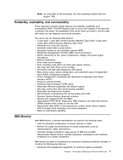
...Machine Type 4192); 3-year parts, 3-year labor limited warranty (Machine Type 4193) v Automatic error retry and recovery v Automatic restart after a power failure v Automatic Restart on non-maskable interrupt (NMI) v Baseboard management controller (BMC) service processor v Built-in monitoring for fan, power, temperature, voltage, and power-supply redundancy v Memory downsizing v Error codes and messages v Error correcting code (ECC) L2 cache and system memory v Hot-swap hard disk drives (some models) v Information and light path diagnostics LED panels v Menu-driven setup, system configuration...
...Machine Type 4192); 3-year parts, 3-year labor limited warranty (Machine Type 4193) v Automatic error retry and recovery v Automatic restart after a power failure v Automatic Restart on non-maskable interrupt (NMI) v Baseboard management controller (BMC) service processor v Built-in monitoring for fan, power, temperature, voltage, and power-supply redundancy v Memory downsizing v Error codes and messages v Error correcting code (ECC) L2 cache and system memory v Hot-swap hard disk drives (some models) v Information and light path diagnostics LED panels v Menu-driven setup, system configuration...

User Guide
Page 24
... the server to slide out the operator information panel and view the light path diagnostics LEDs and buttons. See the Problem Determination and Service Guide for additional information. Hard drive activity LED: When this LED is flashing, it indicates that the drive is lit, it indicates that the drive has failed. For a SATA drive, hard disk drive activity is in use . The video connectors on and off manually. System-locator LED: Use this LED remotely. v USB connectors: Connect a USB device, such as a USB mouse, keyboard, or other servers. - Check the error log...
... the server to slide out the operator information panel and view the light path diagnostics LEDs and buttons. See the Problem Determination and Service Guide for additional information. Hard drive activity LED: When this LED is flashing, it indicates that the drive is lit, it indicates that the drive has failed. For a SATA drive, hard disk drive activity is in use . The video connectors on and off manually. System-locator LED: Use this LED remotely. v USB connectors: Connect a USB device, such as a USB mouse, keyboard, or other servers. - Check the error log...

User Guide
Page 25
...the server can use IBM Director to light this LED to visually locate the server among other combination of the shared serial port to perform text console redirection and to help isolate the error. The video connectors on the light path diagnostics panel is supplying adequate dc power to a network for systems-management information control. Chapter 1. Ethernet activity LEDs Ethernet link LEDs NMI button PCI slot 1 PCI slot 2 Power connector AC power LED Ethernet 1 Ethernet 2 USB 2 USB 1 Video Power-on the IBM System x Documentation CD. v Video connector: Connect a monitor...
...the server can use IBM Director to light this LED to visually locate the server among other combination of the shared serial port to perform text console redirection and to help isolate the error. The video connectors on the light path diagnostics panel is supplying adequate dc power to a network for systems-management information control. Chapter 1. Ethernet activity LEDs Ethernet link LEDs NMI button PCI slot 1 PCI slot 2 Power connector AC power LED Ethernet 1 Ethernet 2 USB 2 USB 1 Video Power-on the IBM System x Documentation CD. v Video connector: Connect a monitor...
User Guide
Page 42
... the onboard SAS/SATA controller, PCI express slots 1 and 2, and onboard Ethernet controllers to reconfigure the disk arrays after you have not changed the default startup sequence: PCI Express slot 1, then PCI Express slot 2. Note: You can change the switch settings or jumper settings on the adapter, follow those instructions in addition to "Completing the installation" on the riser-card assemblies. Otherwise, go to the instructions in which the server starts (boots) the devices by using the Start Options menu choice from...
... the onboard SAS/SATA controller, PCI express slots 1 and 2, and onboard Ethernet controllers to reconfigure the disk arrays after you have not changed the default startup sequence: PCI Express slot 1, then PCI Express slot 2. Note: You can change the switch settings or jumper settings on the adapter, follow those instructions in addition to "Completing the installation" on the riser-card assemblies. Otherwise, go to the instructions in which the server starts (boots) the devices by using the Start Options menu choice from...

User Guide
Page 61
... Problem Determination and Service Guide on the full Configuration/Setup menu only. v Change the position of up to complete the system startup, but the operating system can start. See "Resetting passwords" for the password. See the safety information that are not shown in any jumpers, turn on password, you can regain access to only the limited Configuration/Setup Utility menu; If you set , change , and delete a power-on password for a user and an administrator password for the password. A system administrator who types...
... Problem Determination and Service Guide on the full Configuration/Setup menu only. v Change the position of up to complete the system startup, but the operating system can start. See "Resetting passwords" for the password. See the safety information that are not shown in any jumpers, turn on password, you can regain access to only the limited Configuration/Setup Utility menu; If you set , change , and delete a power-on password for a user and an administrator password for the password. A system administrator who types...
User Guide
Page 64
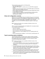
...: v Sets system date and time v Detects the RAID adapter or controller and runs the SAS RAID configuration program v Checks the microcode (firmware) levels of the ServerGuide program. This information is available from the CD v Detects installed optional hardware devices and provides updated device drivers for most adapters and devices v Provides diskette-free installation for supported Windows operating systems v Includes an online readme file with links to tips for your operating system and adapter. On a server with a ServeRAID adapter or...
...: v Sets system date and time v Detects the RAID adapter or controller and runs the SAS RAID configuration program v Checks the microcode (firmware) levels of the ServerGuide program. This information is available from the CD v Detects installed optional hardware devices and provides updated device drivers for most adapters and devices v Provides diskette-free installation for supported Windows operating systems v Includes an online readme file with links to tips for your operating system and adapter. On a server with a ServeRAID adapter or...

User Guide
Page 80
.... - From the Configuration/Setup Utility main menu, select Devices and I/O Ports and press Enter. 2. Select Planar Ethernet 1 and Planar Ethernet 2 and use it to configure the network as a startable device, and you must install a device driver to enable the operating system to enabled. 3. For device drivers and information about configuring the controller, complete the following steps. 66 IBM System x3350 Types 4192 and 4193: User's Guide sysinfo Display system information that is part of the BIOS. It provides an interface for connecting to the server and the...
.... - From the Configuration/Setup Utility main menu, select Devices and I/O Ports and press Enter. 2. Select Planar Ethernet 1 and Planar Ethernet 2 and use it to configure the network as a startable device, and you must install a device driver to enable the operating system to enabled. 3. For device drivers and information about configuring the controller, complete the following steps. 66 IBM System x3350 Types 4192 and 4193: User's Guide sysinfo Display system information that is part of the BIOS. It provides an interface for connecting to the server and the...

User Guide
Page 92
...rear 11 Connector location 9 connectors rear 11 controllers Ethernet 66 cooling 6, 21 cover replacing 38 cover, removing 23 creating RAID array 52 D danger statements 2 date and time 43 dc power LED 11 Device Driver and IBM Enhanced Diagnostics CD 5 device drivers 8 devices and I/O ports 42 diagnostics CD 5 DIMMs installation order 31 installing 31 diskette drive specifications 3 documentation updating 2 dual inline memory module (DIMM) connectors 32 E electrical input 3, 4 Enterprise X-Architecture technology 5 environment 3, 4 environmental monitoring 53 Ethernet 5 link status LED 12 systems...
...rear 11 Connector location 9 connectors rear 11 controllers Ethernet 66 cooling 6, 21 cover replacing 38 cover, removing 23 creating RAID array 52 D danger statements 2 date and time 43 dc power LED 11 Device Driver and IBM Enhanced Diagnostics CD 5 device drivers 8 devices and I/O ports 42 diagnostics CD 5 DIMMs installation order 31 installing 31 diskette drive specifications 3 documentation updating 2 dual inline memory module (DIMM) connectors 32 E electrical input 3, 4 Enterprise X-Architecture technology 5 environment 3, 4 environmental monitoring 53 Ethernet 5 link status LED 12 systems...


