User Guide
Page 5
...CD 4 Hardware and software requirements . . . . . 4 Using the Documentation Browser 4 Notices and statements in a BladeCenter unit 56 © Copyright IBM Corp. 2011 Updating the blade server configuration . . . . 58 Input/output connectors and devices 58 Chapter 4. Configuring ...install the operating system . . . . 74 Downloading installation instructions . . . . . 74 Chapter 6. Contents Safety v Safety statements vi Chapter 1. Power, controls, and indicators 15 Blade server controls and LEDs 15 Turning on the blade server 18 Turning off the blade server 18 Blade server connectors...
...CD 4 Hardware and software requirements . . . . . 4 Using the Documentation Browser 4 Notices and statements in a BladeCenter unit 56 © Copyright IBM Corp. 2011 Updating the blade server configuration . . . . 58 Input/output connectors and devices 58 Chapter 4. Configuring ...install the operating system . . . . 74 Downloading installation instructions . . . . . 74 Chapter 6. Contents Safety v Safety statements vi Chapter 1. Power, controls, and indicators 15 Blade server controls and LEDs 15 Turning on the blade server 18 Turning off the blade server 18 Blade server connectors...

User Guide
Page 9
... vii DANGER Electrical current from connectors. 4. To Connect: 1. Attach power cords to connect or disconnect signal cables. Turn everything OFF. 2. First, remove power cords from devices. v When possible, use only IBM® Part Number 33F8354 or an equivalent type battery recommended by the...installation, maintenance, or reconfiguration of . Turn everything OFF. 2. Turn device ON. v Connect all cables from outlet. 3. Remove all power cords to this product. CAUTION: When replacing the lithium battery, use one hand only to outlet. 5. Attach signal cables to connectors...
... vii DANGER Electrical current from connectors. 4. To Connect: 1. Attach power cords to connect or disconnect signal cables. Turn everything OFF. 2. First, remove power cords from devices. v When possible, use only IBM® Part Number 33F8354 or an equivalent type battery recommended by the...installation, maintenance, or reconfiguration of . Turn everything OFF. 2. Turn device ON. v Connect all cables from outlet. 3. Remove all power cords to this product. CAUTION: When replacing the lithium battery, use one hand only to outlet. 5. Attach signal cables to connectors...
User Guide
Page 11
Hazardous voltage, current, and energy levels are no serviceable parts inside any part that has this label attached. There are present inside these parts, contact a service technician. If you suspect a problem with one of these components. Statement 13 Safety ix Statement 12 CAUTION: The following label attached. Statement 8 CAUTION: Never remove the cover on a power supply or any component that has the following label indicates a hot surface nearby.
Hazardous voltage, current, and energy levels are no serviceable parts inside any part that has this label attached. There are present inside these parts, contact a service technician. If you suspect a problem with one of these components. Statement 13 Safety ix Statement 12 CAUTION: The following label attached. Statement 8 CAUTION: Never remove the cover on a power supply or any component that has the following label indicates a hot surface nearby.
User Guide
Page 12
.... Statement 32 CAUTION: To avoid personal injury, before installing the blade. Removing power supply modules or turning off the server blades does not turn off the electrical current supplied to the device. x BladeCenter HS22 Type 7870, 1936, and 1911: Installation and User's Guide To avoid these hazards, ensure that is provided with your system...
.... Statement 32 CAUTION: To avoid personal injury, before installing the blade. Removing power supply modules or turning off the server blades does not turn off the electrical current supplied to the device. x BladeCenter HS22 Type 7870, 1936, and 1911: Installation and User's Guide To avoid these hazards, ensure that is provided with your system...

User Guide
Page 21
Notes: 1. Features and specifications Use this table to recognize and use USB media drives and devices. The BladeCenter unit uses USB for the blade server to view specific information about the blade server, such as blade server hardware features and the dimensions of the blade server. Introduction 7 Power, cooling, removable-media drives, external ports, and advanced system management are provided by the BladeCenter unit. 2. Chapter 1. The operating system in the blade server must provide USB support for internal communications with these devices.
Notes: 1. Features and specifications Use this table to recognize and use USB media drives and devices. The BladeCenter unit uses USB for the blade server to view specific information about the blade server, such as blade server hardware features and the dimensions of the blade server. Introduction 7 Power, cooling, removable-media drives, external ports, and advanced system management are provided by the BladeCenter unit. 2. Chapter 1. The operating system in the blade server must provide USB support for internal communications with these devices.
User Guide
Page 23
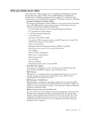
... and device drivers. The IMM operates as , the Integrated Management Module, storage disk drive support, IBM® Director, IBM Enterprise X-Architecture®, microprocessor technology, integrated network support, I/O expansion, large system-memory capacity, light path diagnostics, PCI Express, and power throttling. Local LED control - Chapter 1. Automatic Server Restart (ASR) - Introduction 9 Provides RS-485 interfaces...
... and device drivers. The IMM operates as , the Integrated Management Module, storage disk drive support, IBM® Director, IBM Enterprise X-Architecture®, microprocessor technology, integrated network support, I/O expansion, large system-memory capacity, light path diagnostics, PCI Express, and power throttling. Local LED control - Chapter 1. Automatic Server Restart (ASR) - Introduction 9 Provides RS-485 interfaces...
User Guide
Page 24
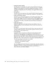
...board. For the most current list of supported DIMMs, see the Advanced-Management-Module documentation or http://www.ibm.com/systems/support/. 10 BladeCenter HS22 Type 7870, 1936, and 1911: Installation and User's Guide With the blade expansion connector you diagnose problems. For ... policy are available: - v PCI Express PCI Express is a serial interface that is inserted into the BladeCenter unit. By enforcing a power policy known as power-domain oversubscription, the BladeCenter unit can add optional I /O expansion The blade server has connectors on LAN® technology. v Integrated...
...board. For the most current list of supported DIMMs, see the Advanced-Management-Module documentation or http://www.ibm.com/systems/support/. 10 BladeCenter HS22 Type 7870, 1936, and 1911: Installation and User's Guide With the blade expansion connector you diagnose problems. For ... policy are available: - v PCI Express PCI Express is a serial interface that is inserted into the BladeCenter unit. By enforcing a power policy known as power-domain oversubscription, the BladeCenter unit can add optional I /O expansion The blade server has connectors on LAN® technology. v Integrated...

User Guide
Page 25
...has the following RAS features: v Customer upgrade of Flash ROM-resident code and diagnostics v Power Policy 24-hour support center v VPD on Memory v Processor presence detect v Advanced Configuration and Power Interface (ACPI) v Automatic server restart (ASR) v Built-in monitoring for temperature, ...Management Module (IMM) v Light path diagnostics feature v Memory parity testing v Registered ECC DDR3 memory v Microprocessor built-in self-test (BIST) during power-on self-test (POST) v Microprocessor serial number access v PCI PMI 2.2 v PCI Express 1.0a v POST v ROM resident diagnostics v Service...
...has the following RAS features: v Customer upgrade of Flash ROM-resident code and diagnostics v Power Policy 24-hour support center v VPD on Memory v Processor presence detect v Advanced Configuration and Power Interface (ACPI) v Automatic server restart (ASR) v Built-in monitoring for temperature, ...Management Module (IMM) v Light path diagnostics feature v Memory parity testing v Registered ECC DDR3 memory v Microprocessor built-in self-test (BIST) during power-on self-test (POST) v Microprocessor serial number access v PCI PMI 2.2 v PCI Express 1.0a v POST v ROM resident diagnostics v Service...

User Guide
Page 29
...documentation on LED: This green LED indicates the power status of the controls and indicators. Power LED Activity LED Location LED Information LED Fault LED Power button NMI button KVM select button/LED Media-tray select button/LED Power-on the IBM® Director CD that there is ready to...The location LED can remotely turn on this information to view power features, turn on and turn off through the Advanced-Management-Module Web interface or through the Advanced Management Module, the BladeCenter unit does not have power permissions assigned to turn on the blade server, or the ...
...documentation on LED: This green LED indicates the power status of the controls and indicators. Power LED Activity LED Location LED Information LED Fault LED Power button NMI button KVM select button/LED Media-tray select button/LED Power-on the IBM® Director CD that there is ready to...The location LED can remotely turn on this information to view power features, turn on and turn off through the Advanced-Management-Module Web interface or through the Advanced Management Module, the BladeCenter unit does not have power permissions assigned to turn on the blade server, or the ...
User Guide
Page 30
... turned off the blade server. It can use the keyboard and mouse, even if the keyboard and mouse have PS/2-style connectors. 16 BladeCenter HS22 Type 7870, 1936, and 1911: Installation and User's Guide If there is lit, it occupies. Fault LED: When this button to switch KVM ... to recognize and use the Advanced-Management-Module Web interface to turn on the IBM® Director CD that a system error has occurred in the Advanced-ManagementModule event log. Local power control is identified by IBM Support. A blade server that information about a system event in the blade server...
... turned off the blade server. It can use the keyboard and mouse, even if the keyboard and mouse have PS/2-style connectors. 16 BladeCenter HS22 Type 7870, 1936, and 1911: Installation and User's Guide If there is lit, it occupies. Fault LED: When this button to switch KVM ... to recognize and use the Advanced-Management-Module Web interface to turn on the IBM® Director CD that a system error has occurred in the Advanced-ManagementModule event log. Local power control is identified by IBM Support. A blade server that information about a system event in the blade server...

User Guide
Page 31
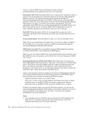
... the error is no response when you press the media-tray select button, you switch the keyboard, video, and mouse to the blade server. Power, controls, and indicators 17 All subsequent switching takes place in the blade server to the blade server. If there is corrected. 2. If you ...that you can take approximately 20 seconds for the blade server to recognize and use the Advanced-Management-Module Web interface to associate the shared BladeCenter unit media tray (removable-media drives) with the storage drive. Note: The operating system in the blade server must provide USB support ...
... the error is no response when you press the media-tray select button, you switch the keyboard, video, and mouse to the blade server. Power, controls, and indicators 17 All subsequent switching takes place in the blade server to the blade server. If there is corrected. 2. If you ...that you can take approximately 20 seconds for the blade server to recognize and use the Advanced-Management-Module Web interface to associate the shared BladeCenter unit media tray (removable-media drives) with the storage drive. Note: The operating system in the blade server must provide USB support ...
User Guide
Page 32
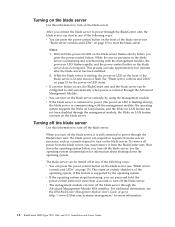
... starts an orderly shutdown of the blade server is still connected to power through the BladeCenter unit. For additional information, see the IBM BladeCenter Management Module User's Guide or go to http://www-03.ibm.com/systems/management/ for more information. 18 BladeCenter HS22 Type 7870, 1936, and 1911: Installation and User's Guide While the service processor in...
... starts an orderly shutdown of the blade server is still connected to power through the BladeCenter unit. For additional information, see the IBM BladeCenter Management Module User's Guide or go to http://www-03.ibm.com/systems/management/ for more information. 18 BladeCenter HS22 Type 7870, 1936, and 1911: Installation and User's Guide While the service processor in...

User Guide
Page 33
... optional devices. Additional information about the error is also lit. Blade server connectors Use this amber LED is corrected. Power, controls, and indicators 19 ! BladeCenter GPU expansion unit LED The following illustration shows the system-board components, including connectors for user-installable optional devices, in... the expansion blade, the fault LED on the blade device on the front of the BladeCenter GPU expansion (BGE) unit. If an error occurs in the blade server. Fault LED Fault LED: When this information to locate...
... optional devices. Additional information about the error is also lit. Blade server connectors Use this amber LED is corrected. Power, controls, and indicators 19 ! BladeCenter GPU expansion unit LED The following illustration shows the system-board components, including connectors for user-installable optional devices, in... the expansion blade, the fault LED on the blade device on the front of the BladeCenter GPU expansion (BGE) unit. If an error occurs in the blade server. Fault LED Fault LED: When this information to locate...
User Guide
Page 37
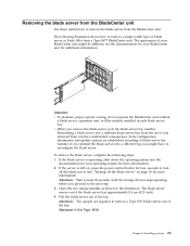
see "Turning off the blade server" on , press the power-control button for additional information. v When you proceed to the next step. 3. Reinstalling a blade server into a different bay, you reinstall the blade server into a different ... blade server out of the blade server bay approximately 0.6 cm (0.25 inch). 4. Attention: Two people are established according to remove the blade server from the BladeCenter unit. if you might be different; The blade server moves out of the bay. Some configuration information and update options are required to reconfigure the...
see "Turning off the blade server" on , press the power-control button for additional information. v When you proceed to the next step. 3. Reinstalling a blade server into a different bay, you reinstall the blade server into a different ... blade server out of the blade server bay approximately 0.6 cm (0.25 inch). 4. Attention: Two people are established according to remove the blade server from the BladeCenter unit. if you might be different; The blade server moves out of the bay. Some configuration information and update options are required to reconfigure the...

User Guide
Page 39
... blade server and expansion units together occupy adjacent blade bays in this document might differ slightly from your blade server, see http://www.ibm.com/servers/eserver/ serverproven/compat/us/. 2. Attention: If a horizontal combination-form-factor (CFFh) expansion card is installed in which you... more expansion units on page 23 for instructions). 3. Installing options 25 Always replace the blade cover before attaching it to power the blade bays in a BladeCenter unit, remove it (see "Removing the blade server cover" on your hardware. To determine the type and number of...
... blade server and expansion units together occupy adjacent blade bays in this document might differ slightly from your blade server, see http://www.ibm.com/servers/eserver/ serverproven/compat/us/. 2. Attention: If a horizontal combination-form-factor (CFFh) expansion card is installed in which you... more expansion units on page 23 for instructions). 3. Installing options 25 Always replace the blade cover before attaching it to power the blade bays in a BladeCenter unit, remove it (see "Removing the blade server cover" on your hardware. To determine the type and number of...

User Guide
Page 49
... expansion-unit riser assembly and install the riser assembly into the expansion unit system board, as shown in the following illustration. 10. Connect the auxiliary power cable (A), as shown in the following illustration. Firmly slide the assemblies together until the tray-release button securely locks the panels. 13. Turn over the...
... expansion-unit riser assembly and install the riser assembly into the expansion unit system board, as shown in the following illustration. 10. Connect the auxiliary power cable (A), as shown in the following illustration. Firmly slide the assemblies together until the tray-release button securely locks the panels. 13. Turn over the...

User Guide
Page 50
...in the illustration above. Removing a GPU adapter from the BladeCenter GPU expansion unit Use this document might differ slightly from the GPU adapter, as shown in the following illustration. 36 BladeCenter HS22 Type 7870, 1936, and 1911: Installation and User's Guide Before ...you begin, read "Safety" on page v and "Installation guidelines" on page 24 for instructions). 3. Disconnect the auxiliary power cable (A) from your hardware. The illustrations in a BladeCenter unit, remove ...
...in the illustration above. Removing a GPU adapter from the BladeCenter GPU expansion unit Use this document might differ slightly from the GPU adapter, as shown in the following illustration. 36 BladeCenter HS22 Type 7870, 1936, and 1911: Installation and User's Guide Before ...you begin, read "Safety" on page v and "Installation guidelines" on page 24 for instructions). 3. Disconnect the auxiliary power cable (A) from your hardware. The illustrations in a BladeCenter unit, remove ...

User Guide
Page 68
... optional devices, you removed one to install other devices (see "Installing an optional expansion unit" on page 25 for additional information. 54 BladeCenter HS22 Type 7870, 1936, and 1911: Installation and User's Guide Reinstall the optional expansion unit, if you might have to run the blade server Setup ... Hazardous energy is present when the blade server is connected to electrical outlets, you must wait until the power-on LED on page 59). Reinstall the blade server into the BladeCenter unit (see "Closing the blade server cover" on page 56). 4. See the documentation that has its...
... optional devices, you removed one to install other devices (see "Installing an optional expansion unit" on page 25 for additional information. 54 BladeCenter HS22 Type 7870, 1936, and 1911: Installation and User's Guide Reinstall the optional expansion unit, if you might have to run the blade server Setup ... Hazardous energy is present when the blade server is connected to electrical outlets, you must wait until the power-on LED on page 59). Reinstall the blade server into the BladeCenter unit (see "Closing the blade server cover" on page 56). 4. See the documentation that has its...
User Guide
Page 70
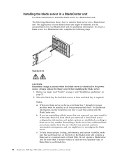
... you might be installed in all four power-module bays. For additional information, see the documentation for your BladeCenter unit might have to install the blade server in a BladeCenter unit. Reinstalling a blade server into a BladeCenter unit. see the Installation and User's Guide that each blade bay. 56 BladeCenter HS22 Type 7870, 1936, and 1911: Installation and User...
... you might be installed in all four power-module bays. For additional information, see the documentation for your BladeCenter unit might have to install the blade server in a BladeCenter unit. Reinstalling a blade server into a BladeCenter unit. see the Installation and User's Guide that each blade bay. 56 BladeCenter HS22 Type 7870, 1936, and 1911: Installation and User...

User Guide
Page 71
... does not respond until it stops. 5. Slide the blade server into the bay. The power-on LED flashes rapidly, and the power-control button on the BladeCenter T unit (BladeCenter T unit only). Optional: Write identifying information on one that comes with the BladeCenter T unit. See "Updating the blade server configuration" on page 58 and Chapter 5, "Installing...
... does not respond until it stops. 5. Slide the blade server into the bay. The power-on LED flashes rapidly, and the power-control button on the BladeCenter T unit (BladeCenter T unit only). Optional: Write identifying information on one that comes with the BladeCenter T unit. See "Updating the blade server configuration" on page 58 and Chapter 5, "Installing...


