Hard Drive Specifications
Page 6
... 6.6 Reset timings 37 6.7 PIO Timings 38 6.7.1 D M A Timings (Single Word 39 6.7.2 D M A Timings (Multiword 40 6.8 Drive Address Setting 41 6.8.1 Default Setting 41 6.9 Addressing of DTNA-2xxxx 2.5 inch H D D ATA Interface Specification 43 7.0 General 45 7.1 Introduction 45 7.2 Terminology 45 8.0 Deviations From Standard 47 9.0 Registers 49 9.1 Alternate Status Register 49 9.2 Command Register 50 9.3 Cylinder High Register 50 9.4 Cylinder Low Register 50 9.5 Data Register 50 9.6 Device Control Register 51 9.7 Drive Address Register 51 9.8 Device/Head Register 51 9.9 Error...
... 6.6 Reset timings 37 6.7 PIO Timings 38 6.7.1 D M A Timings (Single Word 39 6.7.2 D M A Timings (Multiword 40 6.8 Drive Address Setting 41 6.8.1 Default Setting 41 6.9 Addressing of DTNA-2xxxx 2.5 inch H D D ATA Interface Specification 43 7.0 General 45 7.1 Introduction 45 7.2 Terminology 45 8.0 Deviations From Standard 47 9.0 Registers 49 9.1 Alternate Status Register 49 9.2 Command Register 50 9.3 Cylinder High Register 50 9.4 Cylinder Low Register 50 9.5 Data Register 50 9.6 Device Control Register 51 9.7 Drive Address Register 51 9.8 Device/Head Register 51 9.9 Error...
Hard Drive Specifications
Page 17
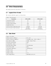
Figure 3. Drive Parameter Descriptions Logical Head Number Logical Sectors/Track Logical Cylinder Number Logical Sector Size Total Customer Usable Data Sectors Total Customer Usable Data Bytes DTNA-21800 16 63 3500 512 3 528 000 1800 MB (1,806,336,000) DTNA-22160 16 63 4200 512 4 233 600 2160 MB (2,167,603,200) 3.2 Data Sheet Figure 4. Data Sheet Media transfer rate [Mb/sec] Interface transfer rate [MB/sec] Data buffer size [ KB] Rotational speed [RPM] Average latency [msec] Recording density...
Figure 3. Drive Parameter Descriptions Logical Head Number Logical Sectors/Track Logical Cylinder Number Logical Sector Size Total Customer Usable Data Sectors Total Customer Usable Data Bytes DTNA-21800 16 63 3500 512 3 528 000 1800 MB (1,806,336,000) DTNA-22160 16 63 4200 512 4 233 600 2160 MB (2,167,603,200) 3.2 Data Sheet Figure 4. Data Sheet Media transfer rate [Mb/sec] Interface transfer rate [MB/sec] Data buffer size [ KB] Rotational speed [RPM] Average latency [msec] Recording density...

Hard Drive Specifications
Page 43
... power up to reset the HDD. These are on the same AT interface cable, to avoid master-master or slave-slave configurations. The data on the bus shall be selected. (SeeFigure 27 on page 42 .) This line is used to Figure 26 on the rising edge of the Command Block Registers (Data, Error{Features when written}, Sector Count, Sector Number, Cylinder Low, Cylinder High, Drive/Head and Status{Command when written} register) can be selected...
... power up to reset the HDD. These are on the same AT interface cable, to avoid master-master or slave-slave configurations. The data on the bus shall be selected. (SeeFigure 27 on page 42 .) This line is used to Figure 26 on the rising edge of the Command Block Registers (Data, Error{Features when written}, Sector Count, Sector Number, Cylinder Low, Cylinder High, Drive/Head and Status{Command when written} register) can be selected...

Hard Drive Specifications
Page 44
... a valid Execute Drive Diagnostics command for drive 1 to the internal logic circuits and " + 5 V MOTOR" is a 3-state line with -DMACK. This signal is available. This signal shall be asserted by an external switch circuit to reduce power consumption to indicate that will be isolated by connecting " + 5 V MOTOR" line into the system power source directly. There are two input pins for + 5 V power supply, " + 5 V LOGIC" and...
... a valid Execute Drive Diagnostics command for drive 1 to the internal logic circuits and " + 5 V MOTOR" is a 3-state line with -DMACK. This signal is available. This signal shall be asserted by an external switch circuit to reduce power consumption to indicate that will be isolated by connecting " + 5 V MOTOR" line into the system power source directly. There are two input pins for + 5 V power supply, " + 5 V LOGIC" and...
Hard Drive Specifications
Page 53
... Vendor Specific Function. The command which is executed first right after power on reset or hard reset when the initial power mode at power on is attached to DTNA-xxxxx. Format Unit Function Protected Area Function 7.2 Terminology Device Host First Command Device indicates DTNA-xxxxx. The interface conforms to the Working Document of Information technology - with certain limitations described in 8.0, " Deviations From Standard" on October 26, 1995. Security Mode Feature Set...
... Vendor Specific Function. The command which is executed first right after power on reset or hard reset when the initial power mode at power on is attached to DTNA-xxxxx. Format Unit Function Protected Area Function 7.2 Terminology Device Host First Command Device indicates DTNA-xxxxx. The interface conforms to the Working Document of Information technology - with certain limitations described in 8.0, " Deviations From Standard" on October 26, 1995. Security Mode Feature Set...

Hard Drive Specifications
Page 73
... lock function is enabled and the User Password is locked on next power on reset or hard reset. Device Unlocked mode The device enables all commands except those which can be used for this mode via a Master Password. High level security When the device lock function is enabled and the User Password is entered by a system user. User Password The User Password should be given or changed by a security unlock or a security erase unit command. Device Locked mode The device disables media access commands after power on . If a password is not set this mode until power...
... lock function is enabled and the User Password is locked on next power on reset or hard reset. Device Unlocked mode The device enables all commands except those which can be used for this mode via a Master Password. High level security When the device lock function is enabled and the User Password is entered by a system user. User Password The User Password should be given or changed by a security unlock or a security erase unit command. Device Locked mode The device disables media access commands after power on . If a password is not set this mode until power...

Hard Drive Specifications
Page 74
... lock function to a new Master Password from default Master Password using the Security Set Password command, without enabling the Device Lock Function. 10.7.4.2 User Password setting When a User Password is set the master password even if only single level password protection is powered on. < Setting password > POR V Set Password with user password. 10.7.4 Operation example 10.7.4.1 Master Password setting The system manufacturer/dealer can unlock the device which is locked with User Password V Normal operation V Power off POR > Device unlocked mode 66 OEM Specifications of DTNA...
... lock function to a new Master Password from default Master Password using the Security Set Password command, without enabling the Device Lock Function. 10.7.4.2 User Password setting When a User Password is set the master password even if only single level password protection is powered on. < Setting password > POR V Set Password with user password. 10.7.4 Operation example 10.7.4.1 Master Password setting The system manufacturer/dealer can unlock the device which is locked with User Password V Normal operation V Power off POR > Device unlocked mode 66 OEM Specifications of DTNA...

Hard Drive Specifications
Page 75
... Unlock mode V Erase Prepare Erase Unit Password Match ? N Y Complete Erase Unit V Lock function Disable V V Media access Non media access command (*1) command (*1) Reject V Complete V V > Normal operation : All commands are available V Freeze Lock command V Enter Device Frozen mode Normal Operation except Set Password, Disable Password, Erase Unit, Unlock commands. (*1) refer to c in Figure 43 on page 69 Figure 41. 10.7.4.3 Operation from POR after User Password is set When Device Lock Function is enabled, the device rejects media access command until an Security Unlock command...
... Unlock mode V Erase Prepare Erase Unit Password Match ? N Y Complete Erase Unit V Lock function Disable V V Media access Non media access command (*1) command (*1) Reject V Complete V V > Normal operation : All commands are available V Freeze Lock command V Enter Device Frozen mode Normal Operation except Set Password, Disable Password, Erase Unit, Unlock commands. (*1) refer to c in Figure 43 on page 69 Figure 41. 10.7.4.3 Operation from POR after User Password is set When Device Lock Function is enabled, the device rejects media access command until an Security Unlock command...

Hard Drive Specifications
Page 77
...Check Power Mode Execute Device Diagnostic Format Track Format Unit Identify Device Identify Device DMA Idle Idle Immediate Initialize Device Parameters Read Buffer Read DMA (w/o retry) Read DMA (w/retry) Read Long (w/o retry) Read Long (w/retry) Read Multiple Read Native Max LBA/CYL Read Sector(s) (w/o retry) Read Sector(s) (w/retry) Read Verify Sector(s) (w/o retry) Read Verify Sector(s) (w/retry) Recalibrate Security Disable Password Security Erase Prepare Security Erase Unit Security Freeze Lock Security Set Password Security Unlock Seek Set Features Set Max LBA/CYL Set Multiple Mode Sleep...
...Check Power Mode Execute Device Diagnostic Format Track Format Unit Identify Device Identify Device DMA Idle Idle Immediate Initialize Device Parameters Read Buffer Read DMA (w/o retry) Read DMA (w/retry) Read Long (w/o retry) Read Long (w/retry) Read Multiple Read Native Max LBA/CYL Read Sector(s) (w/o retry) Read Sector(s) (w/retry) Read Verify Sector(s) (w/o retry) Read Verify Sector(s) (w/retry) Recalibrate Security Disable Password Security Erase Prepare Security Erase Unit Security Freeze Lock Security Set Password Security Unlock Seek Set Features Set Max LBA/CYL Set Multiple Mode Sleep...

Hard Drive Specifications
Page 83
....1 Data In Commands These commands are: Identify Device Read Buffer Read Long Read Multiple Read Sectors SMART Read Attribute Values SMART Read Attribute Thresholds Execution includes the transfer of one sector (or block) of data is available for transfer to the Command register while B S Y = 1 or D R Q = 1 is completed. Interrupts are cleared when the host reads the Status Register, issues a reset, or writes to the Features, Sector Count, Sector Number, Cylinder, and Device/Head Registers. 2. The device sets B S Y = 1 and prepares for data transfer...
....1 Data In Commands These commands are: Identify Device Read Buffer Read Long Read Multiple Read Sectors SMART Read Attribute Values SMART Read Attribute Thresholds Execution includes the transfer of one sector (or block) of data is available for transfer to the Command register while B S Y = 1 or D R Q = 1 is completed. Interrupts are cleared when the host reads the Status Register, issues a reset, or writes to the Features, Sector Count, Sector Number, Cylinder, and Device/Head Registers. 2. The device sets B S Y = 1 and prepares for data transfer...

Hard Drive Specifications
Page 84
... Data Register are : Format Track Security Disable Password Security Erase Unit Security Set Password Security Unlock Write Buffer Write Long Write Multiple 76 OEM Specifications of Device/Head register on issuing the command. The errored location will be available to be corrected and the transfer will then store the error status in response to the host. 4. The device clears the interrupt in the Error Register, and interrupt the host. The device sets D R Q = 0 after the sector has been transferred...
... Data Register are : Format Track Security Disable Password Security Erase Unit Security Set Password Security Unlock Write Buffer Write Long Write Multiple 76 OEM Specifications of Device/Head register on issuing the command. The errored location will be available to be corrected and the transfer will then store the error status in response to the host. 4. The device clears the interrupt in the Error Register, and interrupt the host. The device sets D R Q = 0 after the sector has been transferred...
Hard Drive Specifications
Page 101
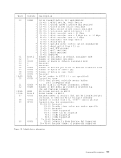
Word 00 01 02 03 04 05 06 07 08 09 10 19 20 21 22 23 26 27 46 47 48 49 50 Content Description 045AH * * * * * Note.1 0 * 0010H 0 * 0 * 003FH 0000H * 0000H * 0000H * XXXX 0003H * 00C0H * 00XXH XXXX Note.2 0010H 0000H 0F00H * 0000H Drive classification, bit assignments: 15(=0): 1=ATAPI device, 0=ATA device 14(=0): 1=format speed tolerance gap required 13(=0): 1=track offset option available 12(=0): 1=data strobe offset option available 11(=0): 1=rotational speed tolerance > 0.5% 10(=1): 1=disk transfer rate > 10 Mbps 9(=0): 1=disk transfer rate > 5 Mbps but
Word 00 01 02 03 04 05 06 07 08 09 10 19 20 21 22 23 26 27 46 47 48 49 50 Content Description 045AH * * * * * Note.1 0 * 0010H 0 * 0 * 003FH 0000H * 0000H * 0000H * XXXX 0003H * 00C0H * 00XXH XXXX Note.2 0010H 0000H 0F00H * 0000H Drive classification, bit assignments: 15(=0): 1=ATAPI device, 0=ATA device 14(=0): 1=format speed tolerance gap required 13(=0): 1=track offset option available 12(=0): 1=data strobe offset option available 11(=0): 1=rotational speed tolerance > 0.5% 10(=1): 1=disk transfer rate > 10 Mbps 9(=0): 1=disk transfer rate > 5 Mbps but
Hard Drive Specifications
Page 102
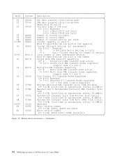
...) ATA 3 X3T10 2008D revision 1 Figure 55. Continued --- 94 OEM Specifications of the capacity Current Multiple setting. bit assignments 15 9(=0) Reserved 8 1= Multiple Sector Setting is Valid 70 xxh = Current setting for number of sectors Total Number of User Addressable Sectors Word 60 specifies the low word of the number Single Word DMA Transfer Capability 15 8 Single word DMA transfer mode active 7 0(=7) Single word DMA transfer modes supported (support mode 0,1 and 2) Multiword DMA Transfer...
...) ATA 3 X3T10 2008D revision 1 Figure 55. Continued --- 94 OEM Specifications of the capacity Current Multiple setting. bit assignments 15 9(=0) Reserved 8 1= Multiple Sector Setting is Valid 70 xxh = Current setting for number of sectors Total Number of User Addressable Sectors Word 60 specifies the low word of the number Single Word DMA Transfer Capability 15 8 Single word DMA transfer mode active 7 0(=7) Single word DMA transfer modes supported (support mode 0,1 and 2) Multiword DMA Transfer...
Hard Drive Specifications
Page 103
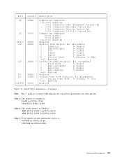
...veder specific. Bit assignments 0 Write Cache 1= Enable 1 Read Look ahead 1= Enable 2 Reverting 1= Enable 3 Auto reassign 1= Enable 4 15 Reserved XXXXH * Reserved 000XH * Initial Power Mode Selection. Note. The model number in 'Content' field indicates the use of user addressable sectors is 'IBM-DTNA-22160' for DTNA-22160, 'IBM-DTNA-21800' for DTNA-21800, Note 3. Identify device information --- Word 82 83 84 127 128 129 130 131 132 255 Content Description 000BH Command set supported 15 4(=0) Reserved 3(=1) 1=supports Power Management Feature Set 2(=0) 1=supports...
...veder specific. Bit assignments 0 Write Cache 1= Enable 1 Read Look ahead 1= Enable 2 Reverting 1= Enable 3 Auto reassign 1= Enable 4 15 Reserved XXXXH * Reserved 000XH * Initial Power Mode Selection. Note. The model number in 'Content' field indicates the use of user addressable sectors is 'IBM-DTNA-22160' for DTNA-22160, 'IBM-DTNA-21800' for DTNA-21800, Note 3. Identify device information --- Word 82 83 84 127 128 129 130 131 132 255 Content Description 000BH Command set supported 15 4(=0) Reserved 3(=1) 1=supports Power Management Feature Set 2(=0) 1=supports...

Hard Drive Specifications
Page 107
... 3.1, " Logical Drive Format" on page 9, and related description is received. Initialize Device Parameters Command (91h) The Initialize Device Parameters command enables the host to avoid invalid number of cylinder beyond FFFFh, which will cause performance degradation of sectors per track, but there is powered off. The device is no sector per cylinder. Words 54-58 in effect until following condition needs to be satisfied to set instead of heads minus...
... 3.1, " Logical Drive Format" on page 9, and related description is received. Initialize Device Parameters Command (91h) The Initialize Device Parameters command enables the host to avoid invalid number of cylinder beyond FFFFh, which will cause performance degradation of sectors per track, but there is powered off. The device is no sector per cylinder. Words 54-58 in effect until following condition needs to be satisfied to set instead of heads minus...
Hard Drive Specifications
Page 115
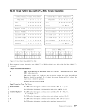
...1 does LBA addressing mode. D = 0 selects the master device and D = 1 selects the slave device. 12.14 Read Native Max LBA/CYL (F8h: Vendor Specific) Command Block Output Registers Register 76543210 Data Feature Sector Count Sector Number Cylinder Low Cylinder High Device/Head 1L1D Command 11111000 Command Block Input Registers Register 76543210 Data Error ...See Below... Read Native Max LBA/CYL (F8h) | This command returns the native max LBA/CYL of the Device/Head Register should be specified. Input Parameters From The Device | Sector Number In LBA mode, this...
...1 does LBA addressing mode. D = 0 selects the master device and D = 1 selects the slave device. 12.14 Read Native Max LBA/CYL (F8h: Vendor Specific) Command Block Output Registers Register 76543210 Data Feature Sector Count Sector Number Cylinder Low Cylinder High Device/Head 1L1D Command 11111000 Command Block Input Registers Register 76543210 Data Error ...See Below... Read Native Max LBA/CYL (F8h) | This command returns the native max LBA/CYL of the Device/Head Register should be specified. Input Parameters From The Device | Sector Number In LBA mode, this...
Hard Drive Specifications
Page 125
.... | DTNA-22160 | DTNA-21800 about 9min.00sec. This command disables the security mode feature (device lock function), however the master password is set. At this command is initialized correctly. And, the defective sector information and the reassigned sector information for both the Master Password and the User Password, and then the device only erases all user data will be initialized to the Security Erase Unit command. The execution time of this time, the initialized sector of data is not verified with write operation. If...
.... | DTNA-22160 | DTNA-21800 about 9min.00sec. This command disables the security mode feature (device lock function), however the master password is set. At this command is initialized correctly. And, the defective sector information and the reassigned sector information for both the Master Password and the User Password, and then the device only erases all user data will be initialized to the Security Erase Unit command. The execution time of this time, the initialized sector of data is not verified with write operation. If...
Hard Drive Specifications
Page 134
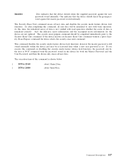
... command sets max | cylinder number = 0, the device returns aborted error to as a default value. Once device receives this command+1)/(16 x 63). So the remainder of DEVICE/HEAD, Cylinder High Cylinder Low and Sector Number | specify the max LBA. In LBA mode,if the command sets the LBA that . | In LBA mode, the Head number of (Set | number by this command, all accesses beyond that LBA/CYL are rejected with setting ABORT bit in a range of | DEVICE/HEAD and Sector Number are ignored. The default value(Max head number = 15, Max sector | number = 63) is used...
... command sets max | cylinder number = 0, the device returns aborted error to as a default value. Once device receives this command+1)/(16 x 63). So the remainder of DEVICE/HEAD, Cylinder High Cylinder Low and Sector Number | specify the max LBA. In LBA mode,if the command sets the LBA that . | In LBA mode, the Head number of (Set | number by this command, all accesses beyond that LBA/CYL are rejected with setting ABORT bit in a range of | DEVICE/HEAD and Sector Number are ignored. The default value(Max head number = 15, Max sector | number = 63) is used...
Hard Drive Specifications
Page 136
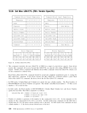
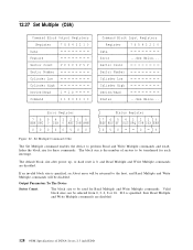
... Parameters To The Device Sector Count. Valid block sizes can be disabled. Set Multiple Command (C6h) The Set Multiple command enables the device to the host, and Read Multiple and Write Multiple commands will be selected from 0, 2, 4, 8 or 16. The block size to be used for Read Multiple and Write Multiple commands. Sector Count Sector Number Cylinder Low Cylinder High Device/Head Status ...See Below... The default block size after power up, or hard reset is specified, then Read Multiple and Write Multiple commands are disabled...
... Parameters To The Device Sector Count. Valid block sizes can be disabled. Set Multiple Command (C6h) The Set Multiple command enables the device to the host, and Read Multiple and Write Multiple commands will be selected from 0, 2, 4, 8 or 16. The block size to be used for Read Multiple and Write Multiple commands. Sector Count Sector Number Cylinder Low Cylinder High Device/Head Status ...See Below... The default block size after power up, or hard reset is specified, then Read Multiple and Write Multiple commands are disabled...
Hard Drive Specifications
Page 174
Function Set 130 Sector Addressing Mode 59 LBA Addressing Mode 59 Logical CHS Addressing Mode 59 Security Disable Password 76, 114 Security Erase Prepare 78, 115 Security Erase Unit 76, 116 Security Freeze Lock 78, 118 Security Mode Feature Set 65 Security Set Password 76, 119 Security Unlock 76, 121 Seek 78, 123 Set Features 78, 124 SET FEATURES Command support Coverage 164 Set Max LBA/CYL 78, 126 Set Multiple 128 Set Multiple Mode 78 Slave 52 Sleep 78, 129 SMART Disable Operations 78 SMART Enable Operations 78 SMART Enable/Disable Attribute Autosave 78 SMART Execute...
Function Set 130 Sector Addressing Mode 59 LBA Addressing Mode 59 Logical CHS Addressing Mode 59 Security Disable Password 76, 114 Security Erase Prepare 78, 115 Security Erase Unit 76, 116 Security Freeze Lock 78, 118 Security Mode Feature Set 65 Security Set Password 76, 119 Security Unlock 76, 121 Seek 78, 123 Set Features 78, 124 SET FEATURES Command support Coverage 164 Set Max LBA/CYL 78, 126 Set Multiple 128 Set Multiple Mode 78 Slave 52 Sleep 78, 129 SMART Disable Operations 78 SMART Enable Operations 78 SMART Enable/Disable Attribute Autosave 78 SMART Execute...


