
Hard Drive Specifications
Page 5
... Capacity 9 3.2 Data Sheet 9 3.3 Cylinder Allocation 10 3.4 Performance Characteristics 10 3.4.1 Command overhead 11 3.4.2 Mechanical Positioning 11 3.4.3 Drive Ready Time 13 3.4.4 Spindle Stop Time 13 3.4.5 Data Transfer Speed 13 3.4.6 Buffering Operation (Lookahead/Write Cache 14 3.4.7 Throughput 15... Plug / Unplug 27 6.1.5 SCSI Bus Electrical Characteristics 28 6.1.6 Auxiliary Connector on 68-pin Model 29 6.2 Option Jumper Block 30 6.2.1 Jumper Signal Description 32 6.2.2 Shipping Default 35 6.3 LED Circuit 36 6.3.1 50-Pin Model 36 6.3.2 68-Pin Model 37 © Copyright...
... Capacity 9 3.2 Data Sheet 9 3.3 Cylinder Allocation 10 3.4 Performance Characteristics 10 3.4.1 Command overhead 11 3.4.2 Mechanical Positioning 11 3.4.3 Drive Ready Time 13 3.4.4 Spindle Stop Time 13 3.4.5 Data Transfer Speed 13 3.4.6 Buffering Operation (Lookahead/Write Cache 14 3.4.7 Throughput 15... Plug / Unplug 27 6.1.5 SCSI Bus Electrical Characteristics 28 6.1.6 Auxiliary Connector on 68-pin Model 29 6.2 Option Jumper Block 30 6.2.1 Jumper Signal Description 32 6.2.2 Shipping Default 35 6.3 LED Circuit 36 6.3.1 50-Pin Model 36 6.3.2 68-Pin Model 37 © Copyright...

Hard Drive Specifications
Page 35
Specification 25 Table of interface signals conform to SFF-8046 as Logical O R with jumper pins on Option Jumper Block. Figure 18. | 6.1.1.5 SCSI Signal Connector (80-pin SE) The pin assignments of Signals Connector Contact Number Signal Name 01 12 Volt Charge 02 12 ...
Specification 25 Table of interface signals conform to SFF-8046 as Logical O R with jumper pins on Option Jumper Block. Figure 18. | 6.1.1.5 SCSI Signal Connector (80-pin SE) The pin assignments of Signals Connector Contact Number Signal Name 01 12 Volt Charge 02 12 ...

Hard Drive Specifications
Page 36
... START SCSI ID (1) SCSI ID (3) | Note: Pin #38,39,40,77,78,79,80 work as Logical O R with SFF-8046 Revision 2.1. | Figure 19. Table of DDRS-3xxxx | 6.1.1.6 SCSI Signal Connector (80-pin LVD) | The 80-pin SCA-2 model uses an AMP connector which is compatible with...
... START SCSI ID (1) SCSI ID (3) | Note: Pin #38,39,40,77,78,79,80 work as Logical O R with SFF-8046 Revision 2.1. | Figure 19. Table of DDRS-3xxxx | 6.1.1.6 SCSI Signal Connector (80-pin LVD) | The 80-pin SCA-2 model uses an AMP connector which is compatible with...

Hard Drive Specifications
Page 37
...-ended transceiver should be 12 meter. System is user responsibility to a maximum of LVD model have active termination feature. It is also driven by drive 5V supply through current limiter and shotky diode, and internal terminator is not changeable. Term.power (#26 pin of 50pin model, #17,18 pins... at both ends of the auxiliary connector on 68 SCSI pin models. The maximum cumulative signal path length between pins 13 and 14 of the jumper block, or connecting pins 9 and 10 of the | bus cable. 6.1.4 Hot Plug / Unplug The 80-pin (SCA-2) model supports Hot Plug/Unplug. The...
...-ended transceiver should be 12 meter. System is user responsibility to a maximum of LVD model have active termination feature. It is also driven by drive 5V supply through current limiter and shotky diode, and internal terminator is not changeable. Term.power (#26 pin of 50pin model, #17,18 pins... at both ends of the auxiliary connector on 68 SCSI pin models. The maximum cumulative signal path length between pins 13 and 14 of the jumper block, or connecting pins 9 and 10 of the | bus cable. 6.1.4 Hot Plug / Unplug The 80-pin (SCA-2) model supports Hot Plug/Unplug. The...

Hard Drive Specifications
Page 39
...) GROUND LED Cathod 12 10 8 6 4 2 (Reserved) (Reserved) (Reserved) | Note: Pin #9 is valid only for SE model. | LVD model has no terminator. The drive conforms SFF-8009 Rev3.0. Pin #8 is for external LED cathod. | If pin #9 is to Option Jumper Block. The setting at Option Jumper Block and the Auxiliary Connector work as -DAS0,1,2,3.
...) GROUND LED Cathod 12 10 8 6 4 2 (Reserved) (Reserved) (Reserved) | Note: Pin #9 is valid only for SE model. | LVD model has no terminator. The drive conforms SFF-8009 Rev3.0. Pin #8 is for external LED cathod. | If pin #9 is to Option Jumper Block. The setting at Option Jumper Block and the Auxiliary Connector work as -DAS0,1,2,3.

Hard Drive Specifications
Page 40
... The 12 positions jumper block shown below is not compatible with previous IBM HDDs such as DPES-xxxxx, DALS-xxxxx. 30 OEM Spec. Some of DDRS-3xxxx These controls work as descrived in 6.1.6, "Auxiliary Connector on 68-pin Model" on page 29. of the above items can be also ...controled through Auxiliary Connector as logical O R between Option Jumper Block and Auxiliary...
... The 12 positions jumper block shown below is not compatible with previous IBM HDDs such as DPES-xxxxx, DALS-xxxxx. 30 OEM Spec. Some of DDRS-3xxxx These controls work as descrived in 6.1.6, "Auxiliary Connector on 68-pin Model" on page 29. of the above items can be also ...controled through Auxiliary Connector as logical O R between Option Jumper Block and Auxiliary...
Hard Drive Specifications
Page 42
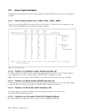
... 10 11 12 13 14 15 Shipping default of 80 pin Shipping default of DDRS-3xxxx Figure 23. If shunt jumper is | not installed, the drive will not spin up unless a START UNIT command is received. | Note: The drive may not spin up while SCSI Bus is disconnected and internal terminator is disabled. ...(SCSI Terminator ON) If a shunt jumper is installed on 50/68-pin drive, the internal terminator on the drive works. 80-pin drive has not internal terminator. | 6.2.1.5 Position 6 on LVD models (Force SCSI Single-End Mode) | If a shunt jumper is installed, the drive is the most significant bit. SCSI ...
... 10 11 12 13 14 15 Shipping default of 80 pin Shipping default of DDRS-3xxxx Figure 23. If shunt jumper is | not installed, the drive will not spin up unless a START UNIT command is received. | Note: The drive may not spin up while SCSI Bus is disconnected and internal terminator is disabled. ...(SCSI Terminator ON) If a shunt jumper is installed on 50/68-pin drive, the internal terminator on the drive works. 80-pin drive has not internal terminator. | 6.2.1.5 Position 6 on LVD models (Force SCSI Single-End Mode) | If a shunt jumper is installed, the drive is the most significant bit. SCSI ...

Hard Drive Specifications
Page 43
... its own SCSI address. Disable Auto Spin Up ,Auto Start Delay & Delay Start Specification 33 6.2.1.6 Disable Unit Attention. (Position 7) Grounding this pin (jumper on off Spin up 6 seconds multiplied | off (80 pin) by SCSI address after POR Figure 24. When both Auto Spin up and Auto Start ...Delayis are enabled, the drive start will be ignored. | Enable Auto Auto Start Spin up Delay Position # > (5) (9) | off (50/68 pin) any | on (80 pin) Delay ...
... its own SCSI address. Disable Auto Spin Up ,Auto Start Delay & Delay Start Specification 33 6.2.1.6 Disable Unit Attention. (Position 7) Grounding this pin (jumper on off Spin up 6 seconds multiplied | off (80 pin) by SCSI address after POR Figure 24. When both Auto Spin up and Auto Start ...Delayis are enabled, the drive start will be ignored. | Enable Auto Auto Start Spin up Delay Position # > (5) (9) | off (50/68 pin) any | on (80 pin) Delay ...

Hard Drive Specifications
Page 44
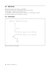
The LED Cathode is provided. 6.2.1.9 Disable SCSI Parity Check (Position 11) Grounding this pin will disable SCSI Parity checking. 6.2.1.10 LED pins (Position 12) The LED pins are used to the current limited + 5 V source provided on Pin #1 of the Option Jumper Block. The LED Anode must be tied to drive an external Light Emitting Diode. LED Circuit 34 OEM Spec. Up to 30 mA of DDRS-3xxxx of sink current capability is then connected to the Pin #2 to complete the circuit. +5V o > < 620 Ohm > / \ o Pin #1 for LED Anode o Pin #2 for LED Cathod /// Figure 25.
The LED Cathode is provided. 6.2.1.9 Disable SCSI Parity Check (Position 11) Grounding this pin will disable SCSI Parity checking. 6.2.1.10 LED pins (Position 12) The LED pins are used to the current limited + 5 V source provided on Pin #1 of the Option Jumper Block. The LED Anode must be tied to drive an external Light Emitting Diode. LED Circuit 34 OEM Spec. Up to 30 mA of DDRS-3xxxx of sink current capability is then connected to the Pin #2 to complete the circuit. +5V o > < 620 Ohm > / \ o Pin #1 for LED Anode o Pin #2 for LED Cathod /// Figure 25.

Hard Drive Specifications
Page 45
.... | Position # : | 12 11 10 9 8 7 6 5 4 3 2 1 | | | oooooooooooo | | oooooooooooo | | | Shunt jumpers are installed at position 2,3,5 and 6 as shipping default of | LVD 68 pin model. Default Jumper Setting of SE 50/68-pin | Shipping Default Setting on LVD 68 pin. | Position # : | 12 11 10 9 8 7 6 5 4 ...3 2 1 | | | oooooooooooo | | oooooooooooo | | | Shunt jumpers are installed at position 2,3 and 5 as shipping...
.... | Position # : | 12 11 10 9 8 7 6 5 4 3 2 1 | | | oooooooooooo | | oooooooooooo | | | Shunt jumpers are installed at position 2,3,5 and 6 as shipping default of | LVD 68 pin model. Default Jumper Setting of SE 50/68-pin | Shipping Default Setting on LVD 68 pin. | Position # : | 12 11 10 9 8 7 6 5 4 ...3 2 1 | | | oooooooooooo | | oooooooooooo | | | Shunt jumpers are installed at position 2,3 and 5 as shipping...
Hard Drive Specifications
Page 46
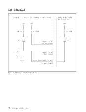
of 50-Pin Model 36 OEM Spec. LED Circuit of DDRS-3xxxx 6.3 LED Circuit Jumper pin #1 and #2 are as shown in 6.3.3, "80-Pin Model" on page 38. The schematics of the the jumper pins, the following pins can be used to drive LED. 68-Pin Model : Auxiliary Connector Pin #8 and #11. 80-Pin Model : SCA-2 Connector Pin #77 as follows. 6.3.1 50-Pin Model DDRS 39130 / DDRS 34560 50 Pin Model +5V o > < 620 Ohm > o Jumper Pin #1 for LED Anode o Jumper Pin #2 for LED Cathod / \ /// Figure 28. Instead of LED circuit on each model are used to drive an external LED.
of 50-Pin Model 36 OEM Spec. LED Circuit of DDRS-3xxxx 6.3 LED Circuit Jumper pin #1 and #2 are as shown in 6.3.3, "80-Pin Model" on page 38. The schematics of the the jumper pins, the following pins can be used to drive LED. 68-Pin Model : Auxiliary Connector Pin #8 and #11. 80-Pin Model : SCA-2 Connector Pin #77 as follows. 6.3.1 50-Pin Model DDRS 39130 / DDRS 34560 50 Pin Model +5V o > < 620 Ohm > o Jumper Pin #1 for LED Anode o Jumper Pin #2 for LED Cathod / \ /// Figure 28. Instead of LED circuit on each model are used to drive an external LED.

Hard Drive Specifications
Page 47
6.3.2 68-Pin Model DDRS 39130 / DDRS 34560 68 Pin Model : : : : 5V : o : Auxiliary : Connector Pin #11 o for LED Anode : : > : < 620 Ohm : > : : Jumper Pin #1 for LED Anode o : : : o / Jumper Pin #2 for LED Cathod \ : : > : < 150 Ohm : > : : Auxiliary : Connector Pin #8 /// o for LED Cathod : : : : Example of 68-Pin Model Specification 37 LED Circuit of Usage : at System Side : : : : : : o : : : : : \/ : \ / LED : : : : : : : : : : : : : : : : : o : : : Figure 29.
6.3.2 68-Pin Model DDRS 39130 / DDRS 34560 68 Pin Model : : : : 5V : o : Auxiliary : Connector Pin #11 o for LED Anode : : > : < 620 Ohm : > : : Jumper Pin #1 for LED Anode o : : : o / Jumper Pin #2 for LED Cathod \ : : > : < 150 Ohm : > : : Auxiliary : Connector Pin #8 /// o for LED Cathod : : : : Example of 68-Pin Model Specification 37 LED Circuit of Usage : at System Side : : : : : : o : : : : : \/ : \ / LED : : : : : : : : : : : : : : : : : o : : : Figure 29.
Hard Drive Specifications
Page 48
of Usage : at System Side : : : +5V : o : : : > : < 150 Ohm : > : : : : \/ : \ / LED : : : : : : : : : : : : : o : : : Figure 30. 6.3.3 80-Pin Model DDRS 39130 / DDRS 34560 80 Pin (SCA 2) Model : : : : +5V +5V : o o : : : > > : 1K Ohm < < 620 Ohm : > > : : : : \/ : LED \ / : Jumper Pin #1 for LED Anode o : : : o / Jumper Pin #2 for LED Cathod \ : : : SCA 2 Connector Pin #77 /// o for LED Cathod : : : Example of DDRS-3xxxx LED Circuit of 80-Pin (SCA-2) Model 38 OEM Spec.
of Usage : at System Side : : : +5V : o : : : > : < 150 Ohm : > : : : : \/ : \ / LED : : : : : : : : : : : : : o : : : Figure 30. 6.3.3 80-Pin Model DDRS 39130 / DDRS 34560 80 Pin (SCA 2) Model : : : : +5V +5V : o o : : : > > : 1K Ohm < < 620 Ohm : > > : : : : \/ : LED \ / : Jumper Pin #1 for LED Anode o : : : o / Jumper Pin #2 for LED Cathod \ : : : SCA 2 Connector Pin #77 /// o for LED Cathod : : : Example of DDRS-3xxxx LED Circuit of 80-Pin (SCA-2) Model 38 OEM Spec.

Hard Drive Specifications
Page 103
...' are recovered under Data Recovery Procedure (DRP) step. MRG (Merge G-List into the Primary Defect List (P-List) during normal operation while the UAI jumper is removed from the drive. QPE (Qualify Post Error) bit allows the Initiator to 1 for compatibility with no effects. If the UAI... jumper is allowed. 7.9.3 Page 0 (Vendor Unique Parameters) BIT 76 5 4 3 2 1 0 BYTE 0 PS RSVD=0 Page Code = 00h BYTE 1 Page Length = 0Eh BYTE 2 QPE UQE Ignore UAI...
...' are recovered under Data Recovery Procedure (DRP) step. MRG (Merge G-List into the Primary Defect List (P-List) during normal operation while the UAI jumper is removed from the drive. QPE (Qualify Post Error) bit allows the Initiator to 1 for compatibility with no effects. If the UAI... jumper is allowed. 7.9.3 Page 0 (Vendor Unique Parameters) BIT 76 5 4 3 2 1 0 BYTE 0 PS RSVD=0 Page Code = 00h BYTE 1 Page Length = 0Eh BYTE 2 QPE UQE Ignore UAI...


