Hard Drive Specifications
Page 6
of DDRS-3xxxx Page Code = 00 74 iv O E M Spec. SCSI Interface Specification 61 7.0 SCSI COMMAND SET 63 7.1 Flag and Link Bits 64 7.2 Abbreviations 65 7.3 Byte ordering conventions 65 7.4 F O R M A T U N I T (04 66 7.4.1 Defect List 66 7.4.2 Defect Descriptor 68 7.5 INQUIRY (12 70 7.6 Inquiry data 71 7.6.1 Inquiry Data Format - EVPD = 0 72 7.6.2 Inquiry Data Format - 6.3.3 80-Pin Model 38 6.4 Environment 39 6.5 Cooling Requirements 40 6.6 DC Power Requirements 41 6.6.1 Start Up Current 42 6.7 Reliability...
of DDRS-3xxxx Page Code = 00 74 iv O E M Spec. SCSI Interface Specification 61 7.0 SCSI COMMAND SET 63 7.1 Flag and Link Bits 64 7.2 Abbreviations 65 7.3 Byte ordering conventions 65 7.4 F O R M A T U N I T (04 66 7.4.1 Defect List 66 7.4.2 Defect Descriptor 68 7.5 INQUIRY (12 70 7.6 Inquiry data 71 7.6.1 Inquiry Data Format - EVPD = 0 72 7.6.2 Inquiry Data Format - 6.3.3 80-Pin Model 38 6.4 Environment 39 6.5 Cooling Requirements 40 6.6 DC Power Requirements 41 6.6.1 Start Up Current 42 6.7 Reliability...
Hard Drive Specifications
Page 11
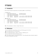
... the specifications of the following IBM 3.5 inch SCSI drives. | DDRS-39130 | − SCSI-3 FAST-20 SE 50-pin (with SCSI terminator) | − SCSI-3 FAST-20 SE 68-pin WIDE (with SCSI terminator) | − SCSI-3 FAST-20 SE 80-pin SCA-2 | − LVD FAST-40 68-pin WIDE (can be used also as SCSI-3 FAST-20 SE) | − LVD FAST-40 80-pin SCA-2 (can be used also as SCSI-3 FAST...
... the specifications of the following IBM 3.5 inch SCSI drives. | DDRS-39130 | − SCSI-3 FAST-20 SE 50-pin (with SCSI terminator) | − SCSI-3 FAST-20 SE 68-pin WIDE (with SCSI terminator) | − SCSI-3 FAST-20 SE 80-pin SCA-2 | − LVD FAST-40 68-pin WIDE (can be used also as SCSI-3 FAST-20 SE) | − LVD FAST-40 80-pin SCA-2 (can be used also as SCSI-3 FAST...

Hard Drive Specifications
Page 13
... transfer ) SCSI-3 SCAM Level-2 support Tagged Command Queuing Multi-initiator support 512 Bytes/sector Interleave factor 1:1 Write Cache Segmented data buffer, 6x64KB or 3x128KB on user choice ECC on the fly Automatic error recovery procedures for read and write commands Self diagnostics on power on and resident diagnostics Automatic Defect Reallocatio 7.5 msec seek time in read operation 7200rpm spindle rotation. Closed loop actuator servo Dedicated head landing zone Automatic actuator lock Informational Exceptions Control Page of IBM...
... transfer ) SCSI-3 SCAM Level-2 support Tagged Command Queuing Multi-initiator support 512 Bytes/sector Interleave factor 1:1 Write Cache Segmented data buffer, 6x64KB or 3x128KB on user choice ECC on the fly Automatic error recovery procedures for read and write commands Self diagnostics on power on and resident diagnostics Automatic Defect Reallocatio 7.5 msec seek time in read operation 7200rpm spindle rotation. Closed loop actuator servo Dedicated head landing zone Automatic actuator lock Informational Exceptions Control Page of IBM...
Hard Drive Specifications
Page 19
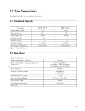
... chapter provides the characteristics of the drive. 3.1 Formatted Capacity Description Label Capacity (MB) Bytes per Sector Sectors per Track Number of heads Number of disks Number of buffer segments Rotational speed [RPM] Recording density [Kbpi] Track density [TPI] Areal density [Mb/sq.in.] Data zone 109 to /from buffer ( Interface transfer rate ) [ Mbyte/sec] | Data buffer size Number of LBAs Total Logical Data Bytes Figure 1. Formatted Capacity DDRS-39130 9130 512 165-264 10 5 17,850...
... chapter provides the characteristics of the drive. 3.1 Formatted Capacity Description Label Capacity (MB) Bytes per Sector Sectors per Track Number of heads Number of disks Number of buffer segments Rotational speed [RPM] Recording density [Kbpi] Track density [TPI] Areal density [Mb/sq.in.] Data zone 109 to /from buffer ( Interface transfer rate ) [ Mbyte/sec] | Data buffer size Number of LBAs Total Logical Data Bytes Figure 1. Formatted Capacity DDRS-39130 9130 512 165-264 10 5 17,850...

Hard Drive Specifications
Page 23
.... Drive Ready Time | Model | DDRS-39130 | DDRS-34560 Typical 15.5 [ sec] 10.5 [ sec] Max. 19.9 [ sec] 19.9 [ sec] Ready Power On The condition in which the drive is derived by: (Number of sectors on before ready, the drive ready time becomes longer than the specified value. Data Transfer Speed Description Disk-Buffer Transfer (Zone 0) (Instantaneous) (Sustained) Disk-Buffer Transfer (Zone 7) (Instantaneous) (Sustained) Buffer-Host 50-pin FAST-20 68-pin / 80-pin FAST...
.... Drive Ready Time | Model | DDRS-39130 | DDRS-34560 Typical 15.5 [ sec] 10.5 [ sec] Max. 19.9 [ sec] 19.9 [ sec] Ready Power On The condition in which the drive is derived by: (Number of sectors on before ready, the drive ready time becomes longer than the specified value. Data Transfer Speed Description Disk-Buffer Transfer (Zone 0) (Instantaneous) (Sustained) Disk-Buffer Transfer (Zone 7) (Instantaneous) (Sustained) Buffer-Host 50-pin FAST-20 68-pin / 80-pin FAST...

Hard Drive Specifications
Page 36
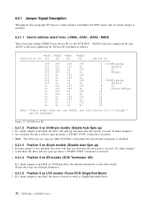
Table of DDRS-3xxxx of Signals | Connector | Contact | Number Signal Name | 01 12 Volt Charge | 02 12 Volt | 03 12 Volt | 04 12 Volt | 05 Reserved | 06 Reserved | 07 -DB(11) | 08 -DB(10) |...) +DB(14) +DB(13) +DB(12) MATED 2 5V Ground 5V Ground ACTIVE LED OUT DELAYED START SCSI ID (1) SCSI ID (3) | Note: Pin #38,39,40,77,78,79,80 work as Logical O R with SFF-8046 Revision 2.1. | Figure 19. | 6.1.1.6 SCSI Signal Connector (80-pin LVD) | The 80-pin SCA-2 model uses an AMP connector which is compatible with jumper pins on Option Jumper Block. 26 OEM Spec.
Table of DDRS-3xxxx of Signals | Connector | Contact | Number Signal Name | 01 12 Volt Charge | 02 12 Volt | 03 12 Volt | 04 12 Volt | 05 Reserved | 06 Reserved | 07 -DB(11) | 08 -DB(10) |...) +DB(14) +DB(13) +DB(12) MATED 2 5V Ground 5V Ground ACTIVE LED OUT DELAYED START SCSI ID (1) SCSI ID (3) | Note: Pin #38,39,40,77,78,79,80 work as Logical O R with SFF-8046 Revision 2.1. | Figure 19. | 6.1.1.6 SCSI Signal Connector (80-pin LVD) | The 80-pin SCA-2 model uses an AMP connector which is compatible with jumper pins on Option Jumper Block. 26 OEM Spec.

Hard Drive Specifications
Page 37
... SCSI pin models. Term.power (#26 pin of 50pin model, #17,18 pins of 68pin model) is provided by drive 5V supply through current limiter and shotky diode, and internal terminator is user responsibility to make sure that all required signals are adequately terminated at both ends of 5 Mbyte transfers per second may extend the cumulative cable length to 4 maximum capacitance (25pF) devices. The 80-pin (SCA-2) model...
... SCSI pin models. Term.power (#26 pin of 50pin model, #17,18 pins of 68pin model) is provided by drive 5V supply through current limiter and shotky diode, and internal terminator is user responsibility to make sure that all required signals are adequately terminated at both ends of 5 Mbyte transfers per second may extend the cumulative cable length to 4 maximum capacitance (25pF) devices. The 80-pin (SCA-2) model...

Hard Drive Specifications
Page 39
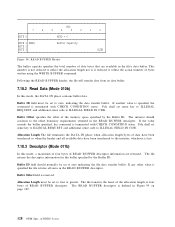
... should be open. The drive conforms SFF-8009 Rev3.0. Tie-down to the ground on 68-pin Model The 68-pin models contain Auxiliary Connector between power connector and 68-pin SCSI connector in addition to the ground is valid only for external LED cathod. | If pin #9 is tied-down to Option Jumper Block. Pin #8 is for SE model. | LVD model has no terminator. The setting at Option Jumper Block...
... should be open. The drive conforms SFF-8009 Rev3.0. Tie-down to the ground on 68-pin Model The 68-pin models contain Auxiliary Connector between power connector and 68-pin SCSI connector in addition to the ground is valid only for external LED cathod. | If pin #9 is tied-down to Option Jumper Block. Pin #8 is for SE model. | LVD model has no terminator. The setting at Option Jumper Block...
Hard Drive Specifications
Page 42
... a START UNIT command is received. | Note: The drive may not spin up while SCSI Bus is disconnected and internal terminator is disabled. | 6.2.1.3 Position 5 on 80-pin models (Disable Auto Spin up) | If shunt jumper is not installed, the drive will not spin up automatically after power on LVD models (Force SCSI Single-End Mode) | If a shunt jumper is installed, the drive is forced to work as follows. Device ID is...
... a START UNIT command is received. | Note: The drive may not spin up while SCSI Bus is disconnected and internal terminator is disabled. | 6.2.1.3 Position 5 on 80-pin models (Disable Auto Spin up) | If shunt jumper is not installed, the drive will not spin up automatically after power on LVD models (Force SCSI Single-End Mode) | If a shunt jumper is installed, the drive is forced to work as follows. Device ID is...

Hard Drive Specifications
Page 103
... queuing is removed from the drive. SCSI COMMAND SET 93 They will be initialized to zero but may however be set to report only those recovered data errors which are not used during Format Unit command. This is set as 'Ignore' are recovered under Data Recovery Procedure (DRP) step. MRG (Merge G-List into the Primary Defect List (P-List) during normal operation while the UAI jumper is...
... queuing is removed from the drive. SCSI COMMAND SET 93 They will be initialized to zero but may however be set to report only those recovered data errors which are not used during Format Unit command. This is set as 'Ignore' are recovered under Data Recovery Procedure (DRP) step. MRG (Merge G-List into the Primary Defect List (P-List) during normal operation while the UAI jumper is...

Hard Drive Specifications
Page 104
... (Ignore Reassigned LBA) bit is active. ADC (Adaptive Cache Enable), when set to zero for ignoring Recovery Time Limit value and for preventing the drive from reassign processing against reassigned LBA when R C bit (Mode Page 1 byte 2 bit 4) is set to control the operation of a file LED driver. − LED Mode = 0000b The CMDAC bit controls the LED. The EADM bit of DDRS-3xxxx Read(6), Read extend(10), Write(6), Write extend(10), untagged...
... (Ignore Reassigned LBA) bit is active. ADC (Adaptive Cache Enable), when set to zero for ignoring Recovery Time Limit value and for preventing the drive from reassign processing against reassigned LBA when R C bit (Mode Page 1 byte 2 bit 4) is set to control the operation of a file LED driver. − LED Mode = 0000b The CMDAC bit controls the LED. The EADM bit of DDRS-3xxxx Read(6), Read extend(10), Write(6), Write extend(10), untagged...

Hard Drive Specifications
Page 123
... disable all information exception operations including the file idle time function which saves the log select counters. TEST bit of one instructs the drive to zero is not used. DEXCPT (Disable Exception Control) bit of zero instructs the drive to disk and so will be lost at the next interval time, (as sense qualifier 5DFFh. The false drive failure is set to generate false drive notifications at the next power cycle. SCSI COMMAND SET...
... disable all information exception operations including the file idle time function which saves the log select counters. TEST bit of one instructs the drive to zero is not used. DEXCPT (Disable Exception Control) bit of zero instructs the drive to disk and so will be lost at the next interval time, (as sense qualifier 5DFFh. The false drive failure is set to generate false drive notifications at the next power cycle. SCSI COMMAND SET...
Hard Drive Specifications
Page 138
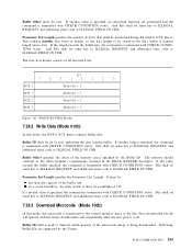
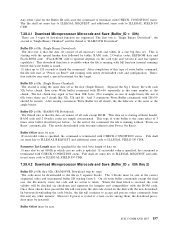
... exceeds the buffer specified, the command is terminated with CHECK CONDITION status. of READ B U F F E R descriptor. 76 BYTE 0 BYTE 1 (MSB) BYTE 2 BYTE 3 BIT 5432 RSVD = 0 Buffer Capacity 10 (LSB) Figure 98. File shall set sense key to ILLEGAL REQUEST and additional sense code to zero indicating the file data transfer buffer. The file returns the descriptor information for the buffer specified by...
... exceeds the buffer specified, the command is terminated with CHECK CONDITION status. of READ B U F F E R descriptor. 76 BYTE 0 BYTE 1 (MSB) BYTE 2 BYTE 3 BIT 5432 RSVD = 0 Buffer Capacity 10 (LSB) Figure 98. File shall set sense key to ILLEGAL REQUEST and additional sense code to zero indicating the file data transfer buffer. The file returns the descriptor information for the buffer specified by...

Hard Drive Specifications
Page 154
... 5 4 3 2 1 0 Command Code = 1Dh PF RSVD =0 SlfTst DevOfl UntOfl Reserved = 0 Parameter List Length (LSB) Reserved = 0 FLAG LINK Figure 112. If the SlfTst bit is executed after power up. If it does not match the expected length of DDRS-3xxxx This includes disk access (seek), R/W channel, and error correction circuitry verification. PF (Page Format) bit set to 0 then a parameter list should be set . Otherwise it 's internal...
... 5 4 3 2 1 0 Command Code = 1Dh PF RSVD =0 SlfTst DevOfl UntOfl Reserved = 0 Parameter List Length (LSB) Reserved = 0 FLAG LINK Figure 112. If the SlfTst bit is executed after power up. If it does not match the expected length of DDRS-3xxxx This includes disk access (seek), R/W channel, and error correction circuitry verification. PF (Page Format) bit set to 0 then a parameter list should be set . Otherwise it 's internal...

Hard Drive Specifications
Page 164
... medium of DDRS-3xxxx This command will cause the entire cache to ILLEGAL FIELD IN CDB. 154 OEM Spec. Additional modes are performed and the command is terminated with the READ B U F F E R command as a diagnostic function for downloading and saving microcode. If another value is specified, no download function are provided for downloading microcode and for testing the file's memory and the SCSI bus integrity. 7.38 WRITE BUFFER...
... medium of DDRS-3xxxx This command will cause the entire cache to ILLEGAL FIELD IN CDB. 154 OEM Spec. Additional modes are performed and the command is terminated with the READ B U F F E R command as a diagnostic function for downloading and saving microcode. If another value is specified, no download function are provided for downloading microcode and for testing the file's memory and the SCSI bus integrity. 7.38 WRITE BUFFER...
Hard Drive Specifications
Page 165
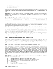
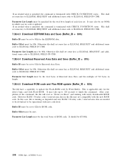
...: SCSI COMMAND SET 155 Buffer Offset specifies the offset of the file. File shall set sense key to ILLEGAL REQUEST and additional sense code to ILLEGAL FIELD IN CDB. 7.38.3 Download Microcode (Mode 100b) In this mode, the DATA OUT phase contains buffer data. If a invalid value is specified, the command is terminated with CHECK CONDITION status. on a sector boundary. Once downloaded the file will operate with...
...: SCSI COMMAND SET 155 Buffer Offset specifies the offset of the file. File shall set sense key to ILLEGAL REQUEST and additional sense code to ILLEGAL FIELD IN CDB. 7.38.3 Download Microcode (Mode 100b) In this mode, the DATA OUT phase contains buffer data. If a invalid value is specified, the command is terminated with CHECK CONDITION status. on a sector boundary. Once downloaded the file will operate with...
Hard Drive Specifications
Page 166
... that the file will accept a command with this mode, a special microcode version will cause the command to ILLEGAL FIELD IN CDB. Note: The Download Microcode mode described in this manner and that the file will be applied to be size of customers for operation. This is for functional upgrade and configuration change by separete data sets) 80h : EEPROM Data 81h : Reserved Area Data 82h : R O M code (only for...
... that the file will accept a command with this mode, a special microcode version will cause the command to ILLEGAL FIELD IN CDB. Note: The Download Microcode mode described in this manner and that the file will be applied to be size of customers for operation. This is for functional upgrade and configuration change by separete data sets) 80h : EEPROM Data 81h : Reserved Area Data 82h : R O M code (only for...
Hard Drive Specifications
Page 167
..., R A M code and 2 Overlay codes are 3 types of 3 times write buffer described just below. The 3 blocks must be specified for this write buffer is running with newly downloaded code and configuration. Buffer ID is 00h. (Single Binary Download) The first one big data set consist of write buffer command, the file will cause the command to ILLEGAL FIELD IN CDB. The newly downloaded code becomes effective after Power On Reset. On...
..., R A M code and 2 Overlay codes are 3 types of 3 times write buffer described just below. The 3 blocks must be specified for this write buffer is running with newly downloaded code and configuration. Buffer ID is 00h. (Single Binary Download) The first one big data set consist of write buffer command, the file will cause the command to ILLEGAL FIELD IN CDB. The newly downloaded code becomes effective after Power On Reset. On...
Hard Drive Specifications
Page 168
... of DDRS-3xxxx In this case, file is running with newly downloaded R O M code. Buffer Offset must be set sense key as degraded and new R A M / Overlay code / reserved area data are needed to be 80h. Buffer Offset must be download to update the Flash-ROM code by Write Buffer. If an invalid value is specified, the command is applicable only for the drive's logic card with Flash-ROM. Parameter List...
... of DDRS-3xxxx In this case, file is running with newly downloaded R O M code. Buffer Offset must be set sense key as degraded and new R A M / Overlay code / reserved area data are needed to be 80h. Buffer Offset must be download to update the Flash-ROM code by Write Buffer. If an invalid value is specified, the command is applicable only for the drive's logic card with Flash-ROM. Parameter List...

Hard Drive Specifications
Page 219
... fail. Hardware Error. Internal logic error. Parameters changed . Unit attention. Data synchronization mark error. (DAM error) Medium error. Degrade Mode. Degrade Mode. Internal target failure. This command is also returned when an unsupported command code is detected while reading the manufacturing defect list or while reading or writing the grown defect list. Logical block address out of the file. Unit attention. Micro code has been changed . Recommend Reassign. Medium error. Log select parameters changed. Configuration sector valid check...
... fail. Hardware Error. Internal logic error. Parameters changed . Unit attention. Data synchronization mark error. (DAM error) Medium error. Degrade Mode. Degrade Mode. Internal target failure. This command is also returned when an unsupported command code is detected while reading the manufacturing defect list or while reading or writing the grown defect list. Logical block address out of the file. Unit attention. Micro code has been changed . Recommend Reassign. Medium error. Log select parameters changed. Configuration sector valid check...


