Hard Drive Specifications
Page 6
ATA Interface Specification 53 7.0 General 55 7.1 Introduction 55 7.2 Terminology 55 8.0 Deviations From Standard 57 9.0 Registers 59 9.1 Alternate Status Register 60 9.2 Command Register 60 9.3 Cylinder High Register 60 9.4 Cylinder Low Register 60 9.5 Data Register 61 9.6 Device Control Register 61 9.7 Drive Address Register 61 9.8 Device/Head Register 62 9.9 Error Register 62 iv O E M Specifications of drive Registers 51 Part 2. 5.5 Vibration and Shock 26 5.5.1 Operating Vibration 26 5.5.2 Non-Operating Vibration 26 5.5.3 Operating Shock 27...
ATA Interface Specification 53 7.0 General 55 7.1 Introduction 55 7.2 Terminology 55 8.0 Deviations From Standard 57 9.0 Registers 59 9.1 Alternate Status Register 60 9.2 Command Register 60 9.3 Cylinder High Register 60 9.4 Cylinder Low Register 60 9.5 Data Register 61 9.6 Device Control Register 61 9.7 Drive Address Register 61 9.8 Device/Head Register 62 9.9 Error Register 62 iv O E M Specifications of drive Registers 51 Part 2. 5.5 Vibration and Shock 26 5.5.1 Operating Vibration 26 5.5.2 Non-Operating Vibration 26 5.5.3 Operating Shock 27...

Hard Drive Specifications
Page 8
....21 Security Erase Unit (F4h 133 12.22 Security Freeze Lock (F5h 135 12.23 Security Set Password (F1h 136 12.24 Security Unlock (F2h 138 12.25 Seek (7xh 140 12.26 Set Features (EFh 141 12.27 Set Max Address (F9h 143 12.28 Set Multiple (C6h 145 12.29 Sleep (E6h/99h 146 12.30 S.M.A.R.T. Function Set (B0h 147 12.30.2 Device Attributes Data Structure...
....21 Security Erase Unit (F4h 133 12.22 Security Freeze Lock (F5h 135 12.23 Security Set Password (F1h 136 12.24 Security Unlock (F2h 138 12.25 Seek (7xh 140 12.26 Set Features (EFh 141 12.27 Set Max Address (F9h 143 12.28 Set Multiple (C6h 145 12.29 Sleep (E6h/99h 146 12.30 S.M.A.R.T. Function Set (B0h 147 12.30.2 Device Attributes Data Structure...
Hard Drive Specifications
Page 17
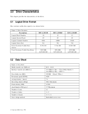
....3 MB/sec Max ( Ultra DMA Mode-2 ) 16.6 MB/sec Max ( PIO-4 ) 420 KB ( Read / Write ) 4200 7.1 286.1 Maximum 19,900 5.7 Maximum 12 1/2 2/ 3/ 4 Embedded sector servo © Copyright IBM Corp. 1998 9 Drive Parameter Descriptions Logical Head Number Logical Sectors/Track Logical Cylinder Number Logical Sector Size Total Customer Usable Data Sectors Total Customer Usable Data Bytes DBCA-203240 16 63 6304 512 6 354 432 3250 MB 3,253,469,184 DBCA-204860 15 63...
....3 MB/sec Max ( Ultra DMA Mode-2 ) 16.6 MB/sec Max ( PIO-4 ) 420 KB ( Read / Write ) 4200 7.1 286.1 Maximum 19,900 5.7 Maximum 12 1/2 2/ 3/ 4 Embedded sector servo © Copyright IBM Corp. 1998 9 Drive Parameter Descriptions Logical Head Number Logical Sectors/Track Logical Cylinder Number Logical Sector Size Total Customer Usable Data Sectors Total Customer Usable Data Bytes DBCA-203240 16 63 6304 512 6 354 432 3250 MB 3,253,469,184 DBCA-204860 15 63...

Hard Drive Specifications
Page 43
... to a register or data register of the Command Block Registers (Data, Error{Features when written}, Sector Count, Sector Number, Cylinder Low, Cylinder High, Drive/Head and Status{Command when written} register) can be selected. (See Figure 37 on page 51.) -CS1 Chip select signal generated from the receipt of the Control Block Registers (Alternate Status{Device Control when written} and Drive Address register) can be selected. (See Figure 37...
... to a register or data register of the Command Block Registers (Data, Error{Features when written}, Sector Count, Sector Number, Cylinder Low, Cylinder High, Drive/Head and Status{Command when written} register) can be selected. (See Figure 37 on page 51.) -CS1 Chip select signal generated from the receipt of the Control Block Registers (Alternate Status{Device Control when written} and Drive Address register) can be selected. (See Figure 37...

Hard Drive Specifications
Page 44
... AT interface cable to avoid drive address 0-0 or 1-1 configuration. 00h. When CSEL is used for + 5 V power supply, " + 5 V Logic" and " + 5 V Motor". The signal level of HSTROBE latch the data from power line shall be asserted by connecting " + 5 V Motor" line into the device. KEY Pin position 20 has no connection pin. It is possible to turn on the interface connector is at the falling edge of data transfer is controlled by...
... AT interface cable to avoid drive address 0-0 or 1-1 configuration. 00h. When CSEL is used for + 5 V power supply, " + 5 V Logic" and " + 5 V Motor". The signal level of HSTROBE latch the data from power line shall be asserted by connecting " + 5 V Motor" line into the device. KEY Pin position 20 has no connection pin. It is possible to turn on the interface connector is at the falling edge of data transfer is controlled by...

Hard Drive Specifications
Page 74
... Set Features command with Feature register = CCh enables the device to revert these parameters to default o o (*3) Number of CHS (set to idle mode. Reset Response Table Note. (*1) (*2) (*3) (*4) (*5) (*6) Execute after the data in Figure 46 on page 67. In other case, the device does not change current mode. According to the initial power mode selection. 66 OEM Specifications of sleep mode, the device goes to 109 minutes. Default value on P O R is set by Initialize Device Parameter) Multiple mode Write cache Read...
... Set Features command with Feature register = CCh enables the device to revert these parameters to default o o (*3) Number of CHS (set to idle mode. Reset Response Table Note. (*1) (*2) (*3) (*4) (*5) (*6) Execute after the data in Figure 46 on page 67. In other case, the device does not change current mode. According to the initial power mode selection. 66 OEM Specifications of sleep mode, the device goes to 109 minutes. Default value on P O R is set by Initialize Device Parameter) Multiple mode Write cache Read...
Hard Drive Specifications
Page 78
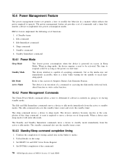
... to reach operating speed. Set DRDY bit and DSC bit in the buffer to respond could be activated. The time to media 2. Confirm the completion of accepting commands, but as the power on reset time. The standby command also sets the standby timer count. 10.4.3 Standby/Sleep command completion timing 1. When a device exits sleep mode it will enter idle mode. Standby command 6. Standby Mode The device interface is capable of writing cached data in...
... to reach operating speed. Set DRDY bit and DSC bit in the buffer to respond could be activated. The time to media 2. Confirm the completion of accepting commands, but as the power on reset time. The standby command also sets the standby timer count. 10.4.3 Standby/Sleep command completion timing 1. When a device exits sleep mode it will enter idle mode. Standby command 6. Standby Mode The device interface is capable of writing cached data in...
Hard Drive Specifications
Page 84
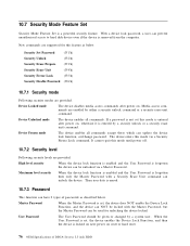
... device lock function is enabled and the User Password is forgotten the device can prevent unauthorized access to hard disk device even if the device is set /change password. When the User Password is removed from the computer. Device Locked mode The device disables media access commands after power on reset or hard reset. 76 OEM Specifications of passwords as below . Media access commands are supported for unlocking the device locked. 10.7 Security Mode Feature Set Security Mode Feature Set is entered by a security unlock or a security erase unit command.
... device lock function is enabled and the User Password is forgotten the device can prevent unauthorized access to hard disk device even if the device is set /change password. When the User Password is removed from the computer. Device Locked mode The device disables media access commands after power on reset or hard reset. 76 OEM Specifications of passwords as below . Media access commands are supported for unlocking the device locked. 10.7 Security Mode Feature Set Security Mode Feature Set is entered by a security unlock or a security erase unit command.

Hard Drive Specifications
Page 85
... the end users, must set the master password even if only single level password protection is required. 10.7.4 Operation example 10.7.4.1 Master Password setting The system manufacturer/dealer can set a new Master Password from default Master Password using the Security Set Password command, without enabling the Device Lock Function. 10.7.4.2 User Password setting When a User Password is set, the device will automatically enter lock mode the next time the device is powered on. < Setting password > POR V Set Password with User Password V Normal operation V Power off POR > Device unlocked mode...
... the end users, must set the master password even if only single level password protection is required. 10.7.4 Operation example 10.7.4.1 Master Password setting The system manufacturer/dealer can set a new Master Password from default Master Password using the Security Set Password command, without enabling the Device Lock Function. 10.7.4.2 User Password setting When a User Password is set, the device will automatically enter lock mode the next time the device is powered on. < Setting password > POR V Set Password with User Password V Normal operation V Power off POR > Device unlocked mode...

Hard Drive Specifications
Page 86
Usual Operation 78 OEM Specifications of DBCA-2xxxxx 2.5 inch H D D 10.7.4.3 Operation from POR after User Password is set When Device Lock Function is enabled, the device rejects media access command until a Security Unlock command is successfully completed. N Y Complete Erase Unit V Lock function Disable V V Media access Non media access command (*1) command (*1) Reject V Complete V V > Normal operation : All commands are available V Freeze Lock command V Enter Device Frozen mode Normal Operation except Set Password, Disable Password, Erase Unit, Unlock commands. (*1) refer to c ...
Usual Operation 78 OEM Specifications of DBCA-2xxxxx 2.5 inch H D D 10.7.4.3 Operation from POR after User Password is set When Device Lock Function is enabled, the device rejects media access command until a Security Unlock command is successfully completed. N Y Complete Erase Unit V Lock function Disable V V Media access Non media access command (*1) command (*1) Reject V Complete V V > Normal operation : All commands are available V Freeze Lock command V Enter Device Frozen mode Normal Operation except Set Password, Disable Password, Erase Unit, Unlock commands. (*1) refer to c ...

Hard Drive Specifications
Page 88
...Command Check Power Mode Execute Device Diagnostic Flush Cache Format Track Format Unit Identify Device Identify Device DMA Idle Idle Immediate Initialize Device Parameters Read Buffer Read DMA (w/o retry) Read DMA (w/retry) Read Long (w/o retry) Read Long (w/retry) Read Multiple Read Native Max Address Read Sector(s) (w/o retry) Read Sector(s) (w/retry) Read Verify Sector(s) (w/o retry) Read Verify Sector(s) (w/retry) Recalibrate Security Disable Password Security Erase Prepare Security Erase Unit Security Freeze Lock Security Set Password Security Unlock Seek Set Features Set Max Address Set...
...Command Check Power Mode Execute Device Diagnostic Flush Cache Format Track Format Unit Identify Device Identify Device DMA Idle Idle Immediate Initialize Device Parameters Read Buffer Read DMA (w/o retry) Read DMA (w/retry) Read Long (w/o retry) Read Long (w/retry) Read Multiple Read Native Max Address Read Sector(s) (w/o retry) Read Sector(s) (w/retry) Read Verify Sector(s) (w/o retry) Read Verify Sector(s) (w/retry) Recalibrate Security Disable Password Security Erase Prepare Security Erase Unit Security Freeze Lock Security Set Password Security Unlock Seek Set Features Set Max Address Set...

Hard Drive Specifications
Page 92
... Reverting to Power on a disk drive this protection is the size of the former protected area. A subsequent Set Max Address command with Abort error status. To allow an alternate bootable operating system to exist in a reserved area on Defaults has been enabled by Set Features command, it is cleared by an Set Max Address command. 10.9.1 Enable/Disable Address Offset Mode Subcommand code 09h Enable Address Offset Mode offsets address Cylinder 0, Head 0, Sector 1, LBA 0, to the...
... Reverting to Power on a disk drive this protection is the size of the former protected area. A subsequent Set Max Address command with Abort error status. To allow an alternate bootable operating system to exist in a reserved area on Defaults has been enabled by Set Features command, it is cleared by an Set Max Address command. 10.9.1 Enable/Disable Address Offset Mode Subcommand code 09h Enable Address Offset Mode offsets address Cylinder 0, Head 0, Sector 1, LBA 0, to the...

Hard Drive Specifications
Page 93
... Set Max Address Command using a non volatile Set Max command. Identify Device data word 86 bit 7 indicates the device is in Address Offset mode. 10.9.3 Exceptions in Address Offset Mode Any commands which access sectors across the original native maximum LBA are rejected with error, even if the access protection is now the reserved area. The former user accessible area is removed by Read Max Address User Accessible Area LBA 0 LBA M Figure 55. General Operation Descriptions 85 Before Enable...
... Set Max Address Command using a non volatile Set Max command. Identify Device data word 86 bit 7 indicates the device is in Address Offset mode. 10.9.3 Exceptions in Address Offset Mode Any commands which access sectors across the original native maximum LBA are rejected with error, even if the access protection is now the reserved area. The former user accessible area is removed by Read Max Address User Accessible Area LBA 0 LBA M Figure 55. General Operation Descriptions 85 Before Enable...

Hard Drive Specifications
Page 100
..., Sector Number, Cylinder, and Device/Head Registers. 2. The host writes the command code to the interrupt, the host reads the Status Register. 6. In response to the Command Register. 3. 11.3 Non-Data Commands These commands are: Check Power Mode Execute Device Diagnostic Flush Cache Format Unit Idle Idle Immediate Initialize Device Parameters Read Native Max Address Read Verify Sectors Recalibrate Security Erase Prepare Security Freeze Lock Seek Set Features Set Max Address Set Multiple Mode Sleep SMART Disable Operations SMART Enable/Disable Attribute Autosave SMART Enable Operations...
..., Sector Number, Cylinder, and Device/Head Registers. 2. The host writes the command code to the interrupt, the host reads the Status Register. 6. In response to the Command Register. 3. 11.3 Non-Data Commands These commands are: Check Power Mode Execute Device Diagnostic Flush Cache Format Unit Idle Idle Immediate Initialize Device Parameters Read Native Max Address Read Verify Sectors Recalibrate Security Erase Prepare Security Freeze Lock Seek Set Features Set Max Address Set Multiple Mode Sleep SMART Disable Operations SMART Enable/Disable Attribute Autosave SMART Enable Operations...

Hard Drive Specifications
Page 115
Word 00 01 02 03 04 05 06 07 08 09 10 19 20 21 22 23 26 27 46 47 48 49 Content Description 045AH * * * * * Note.2 0 * Note.2 0 * 0 * 003FH 0000H * 0000H * 0000H * XXXX 0003H * 0349H * 00XXH * Note.2 Note.2 0010H 0000H * 0F00H * Drive classification, bit assignments: 15(=0): 1=ATAPI device, 0=ATA device 14(=0): 1=format speed tolerance gap required 13(=0): 1=track offset option available 12(=0): 1=data strobe offset option available 11(=0): 1=rotational speed tolerance > 0.5% 10(=1): 1=disk transfer rate > 10 Mbps 9(=0): 1=disk transfer rate > 5 Mbps but
Word 00 01 02 03 04 05 06 07 08 09 10 19 20 21 22 23 26 27 46 47 48 49 Content Description 045AH * * * * * Note.2 0 * Note.2 0 * 0 * 003FH 0000H * 0000H * 0000H * XXXX 0003H * 0349H * 00XXH * Note.2 Note.2 0010H 0000H * 0F00H * Drive classification, bit assignments: 15(=0): 1=ATAPI device, 0=ATA device 14(=0): 1=format speed tolerance gap required 13(=0): 1=track offset option available 12(=0): 1=data strobe offset option available 11(=0): 1=rotational speed tolerance > 0.5% 10(=1): 1=disk transfer rate > 10 Mbps 9(=0): 1=disk transfer rate > 5 Mbps but
Hard Drive Specifications
Page 117
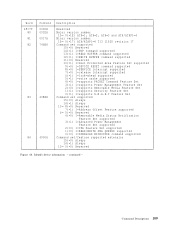
... number 15 0(=17) ATA/ATAPI 4 T13 1153D revision 17 Command set supported 15(=0) Reserved 14(=1) 1=NOP command supported 13(=1) 1=READ BUFFER command supported 12(=1) 1=WRITE BUFFER command supported 11(=0) Reserved 10(=1) 1=Host Protected Area Feature Set supported 9(=0) 1=DEVICE RESET command supported 8(=0) 1=SERVICE interrupt supported 7(=0) 1=release interrupt supported 6(=1) 1=look ahead supported 5(=1) 1=write cache supported 4(=0) 1=supports PACKET Command Feature Set 3(=1) 1=supports Power Management Feature Set 2(=0) 1=supports Removable Media Feature Set 1(=1) 1=supports Security...
... number 15 0(=17) ATA/ATAPI 4 T13 1153D revision 17 Command set supported 15(=0) Reserved 14(=1) 1=NOP command supported 13(=1) 1=READ BUFFER command supported 12(=1) 1=WRITE BUFFER command supported 11(=0) Reserved 10(=1) 1=Host Protected Area Feature Set supported 9(=0) 1=DEVICE RESET command supported 8(=0) 1=SERVICE interrupt supported 7(=0) 1=release interrupt supported 6(=1) 1=look ahead supported 5(=1) 1=write cache supported 4(=0) 1=supports PACKET Command Feature Set 3(=1) 1=supports Power Management Feature Set 2(=0) 1=supports Removable Media Feature Set 1(=1) 1=supports Security...
Hard Drive Specifications
Page 142
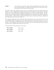
... command disables the security mode feature (device lock function), however the master password is still stored internally within the device and may be completed immediately prior to zero with write operation. Also, the defective sector information and the reassigned sector information for both the Master Password and the User Password, and then the device only erases all user data. The execution time of DBCA-2xxxxx 2.5 inch H D D The Security Erase Unit command erases all user data will be initialized to the Security Erase Unit command. DBCA-206480 DBCA-204860 DBCA...
... command disables the security mode feature (device lock function), however the master password is still stored internally within the device and may be completed immediately prior to zero with write operation. Also, the defective sector information and the reassigned sector information for both the Master Password and the User Password, and then the device only erases all user data. The execution time of DBCA-2xxxxx 2.5 inch H D D The Security Erase Unit command erases all user data will be initialized to the Security Erase Unit command. DBCA-206480 DBCA-204860 DBCA...

Hard Drive Specifications
Page 144
... sets the master password or the user password. This command requests a transfer of a single sector of DBCA-2xxxxx 2.5 inch H D D The data transferred controls the function of this command. 136 OEM Specifications of data from the host including the information specified in Figure 91 on page 137. Sector Count Sector Number Cylinder Low Cylinder High Device/Head Status ...See Below... The security mode feature (device lock function) is enabled by this command, and the device is locked after next power on reset or hard reset. Error Register...
... sets the master password or the user password. This command requests a transfer of a single sector of DBCA-2xxxxx 2.5 inch H D D The data transferred controls the function of this command. 136 OEM Specifications of data from the host including the information specified in Figure 91 on page 137. Sector Count Sector Number Cylinder Low Cylinder High Device/Head Status ...See Below... The security mode feature (device lock function) is enabled by this command, and the device is locked after next power on reset or hard reset. Error Register...

Hard Drive Specifications
Page 153
... error will be disabled. The block size to be selected from 0, 2, 4, 8 or 16. If 0 is 0, and Read Multiple and Write Multiple commands are disabled. The default block size after power up, or hard reset is specified, then Read Multiple and Write Multiple commands are disabled. 12.28 Set Multiple (C6h) Command Block Output Registers Register 76543210 Data Feature Sector Count V V V V V V V V Sector Number Cylinder Low Cylinder High Device/Head 1 1D Command 11000110 Command Block Input Registers Register 76543210 Data Error ...See Below... Error...
... error will be disabled. The block size to be selected from 0, 2, 4, 8 or 16. If 0 is 0, and Read Multiple and Write Multiple commands are disabled. The default block size after power up, or hard reset is specified, then Read Multiple and Write Multiple commands are disabled. 12.28 Set Multiple (C6h) Command Block Output Registers Register 76543210 Data Feature Sector Count V V V V V V V V Sector Number Cylinder Low Cylinder High Device/Head 1 1D Command 11000110 Command Block Input Registers Register 76543210 Data Error ...See Below... Error...

Hard Drive Specifications
Page 188
... 74 S.M.A.R.T. Function Set 147 Sector Addressing Mode 69 LBA Addressing Mode 69 Logical CHS Addressing Mode 69 Security Disable Password 90, 131 Security Erase Prepare 92, 132 Security Erase Unit 90, 133 Security Freeze Lock 92, 135 Security Mode Feature Set 76 Security Set Password 90, 136 Security Unlock 90, 138 Seek 92, 140 Set Features 92, 141 SET FEATURES Command support Coverage 177 Set Max Address 92, 143 Set Multiple 145 Set Multiple Mode 92 Slave 62 Sleep 92, 146 SMART Disable Operations 92 SMART Enable Operations 92 SMART Enable/Disable Attribute Autosave...
... 74 S.M.A.R.T. Function Set 147 Sector Addressing Mode 69 LBA Addressing Mode 69 Logical CHS Addressing Mode 69 Security Disable Password 90, 131 Security Erase Prepare 92, 132 Security Erase Unit 90, 133 Security Freeze Lock 92, 135 Security Mode Feature Set 76 Security Set Password 90, 136 Security Unlock 90, 138 Seek 92, 140 Set Features 92, 141 SET FEATURES Command support Coverage 177 Set Max Address 92, 143 Set Multiple 145 Set Multiple Mode 92 Slave 62 Sleep 92, 146 SMART Disable Operations 92 SMART Enable Operations 92 SMART Enable/Disable Attribute Autosave...


