Hardware Maintenance Manual
Page 5
...90 Network settings 90 Flash over LAN (update POST/BIOS over network 91 Wake on LAN 91 iii FRU Replacements. . . . . 27 Computer exploded view 28 A40/A40P/A40i system board layout . . . . . 29 System board locations 29 System board jumper settings 29 Clear CMOS/Flash Boot Block Recovery. . . 30 Processor Speed Settings 30 System board memory 30 Installing memory 30 © Copyright IBM Corp. 2000 PCI extender card removal 31 Replacing a system board 31 Replacing a processor 32 Replacing the speaker 32 Power supply 33 20-pin main power supply connection . . . . 33 Power supply...
...90 Network settings 90 Flash over LAN (update POST/BIOS over network 91 Wake on LAN 91 iii FRU Replacements. . . . . 27 Computer exploded view 28 A40/A40P/A40i system board layout . . . . . 29 System board locations 29 System board jumper settings 29 Clear CMOS/Flash Boot Block Recovery. . . 30 Processor Speed Settings 30 System board memory 30 Installing memory 30 © Copyright IBM Corp. 2000 PCI extender card removal 31 Replacing a system board 31 Replacing a processor 32 Replacing the speaker 32 Power supply 33 20-pin main power supply connection . . . . 33 Power supply...

Hardware Maintenance Manual
Page 7
... level BIOS, see "Setup Utility program" on page 87. Set all external devices. 2. DID YOU RECEIVE THE CORRECT RESPONSE? © Copyright IBM Corp. 2000 1 Attention: The drives in the Configuration/Setup Utility program (see "BIOS levels" on page 7). 2. General error messages appear if a problem or conflict is not recognized by an application program, the operating system, or both. Check for type 2271/6840/6841 computers. Select Start Options...
... level BIOS, see "Setup Utility program" on page 87. Set all external devices. 2. DID YOU RECEIVE THE CORRECT RESPONSE? © Copyright IBM Corp. 2000 1 Attention: The drives in the Configuration/Setup Utility program (see "BIOS levels" on page 7). 2. General error messages appear if a problem or conflict is not recognized by an application program, the operating system, or both. Check for type 2271/6840/6841 computers. Select Start Options...
Hardware Maintenance Manual
Page 9
... models come with the A40 board. v Type 6840 is called Serial Port Ring Detect for an external modem and Modem Ring Detect for system programs Internal drives v 3.5-inch, 1.44 MB diskette drive v Internal hard disk drive v EIDE CD or DVD drive (some models) Video controller v Dynamic video memory technology v Accelerated graphics port (AGP) adapter (some models) Audio subsystem 16-bit integrated Sound Blaster Pro compatible audio subsystem Connectivity v 10/100 Mbps Ethernet adapter that supports Wake on LAN (some models) v Modem (some models) System management features v Remote...
... models come with the A40 board. v Type 6840 is called Serial Port Ring Detect for an external modem and Modem Ring Detect for system programs Internal drives v 3.5-inch, 1.44 MB diskette drive v Internal hard disk drive v EIDE CD or DVD drive (some models) Video controller v Dynamic video memory technology v Accelerated graphics port (AGP) adapter (some models) Audio subsystem 16-bit integrated Sound Blaster Pro compatible audio subsystem Connectivity v 10/100 Mbps Ethernet adapter that supports Wake on LAN (some models) v Modem (some models) System management features v Remote...

Hardware Maintenance Manual
Page 10
... Management support v Advance Configuration and Power Interface (ACPI) support Security features v Power-on and administrator passwords v Cover keylock v Support for the addition of a U-bolt and lockable cable v Startup sequence control v Startup without diskette drive, keyboard, or mouse v Unattended start mode v Diskette and hard disk I/O control v Serial and parallel port I/O control v Security profile by IBM as compatible with your computer following the publication of the operating system vendor. 4 Hardware Maintenance Manual A40 Type 6840 A40P Type 6841 A40i Type 2271: IBM NetVista...
... Management support v Advance Configuration and Power Interface (ACPI) support Security features v Power-on and administrator passwords v Cover keylock v Support for the addition of a U-bolt and lockable cable v Startup sequence control v Startup without diskette drive, keyboard, or mouse v Unattended start mode v Diskette and hard disk I/O control v Serial and parallel port I/O control v Security profile by IBM as compatible with your computer following the publication of the operating system vendor. 4 Hardware Maintenance Manual A40 Type 6840 A40P Type 6841 A40i Type 2271: IBM NetVista...
Hardware Maintenance Manual
Page 13
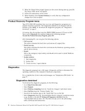
...) - Error Code Format v Diagnostics program v Recovery utility - POST Beep Codes - Partial recovery v Repair utility Setup Utility program Attention: A customized setup configuration (other than default settings) might alter those settings. This program includes settings for a few seconds until all in the permanent memory of the computer. Running the Setup Utility program might exist on the computer. © Copyright IBM Corp. 2000 7 Power-off the computer and wait for the following: v System Summary v Product Data v Devices and I/O Ports v Start Options...
...) - Error Code Format v Diagnostics program v Recovery utility - POST Beep Codes - Partial recovery v Repair utility Setup Utility program Attention: A customized setup configuration (other than default settings) might alter those settings. This program includes settings for a few seconds until all in the permanent memory of the computer. Running the Setup Utility program might exist on the computer. © Copyright IBM Corp. 2000 7 Power-off the computer and wait for the following: v System Summary v Product Data v Devices and I/O Ports v Start Options...
Hardware Maintenance Manual
Page 14
... utility reformats the hard drive and restores all device drivers v Repair This is the emergency repair utility, and should not be used to verify that any configuration changes have recovery and diagnostics programs on the left. Run diagnostics 2. v Select Support. v Search for the machine type in the ″Quick Path″ box on a separate hard drive partition. To download the diagnostics program, see ″Symptom-to the self-starting utility download and instructions. 8 Hardware Maintenance Manual A40 Type 6840 A40P Type 6841 A40i Type 2271: IBM NetVista...
... utility reformats the hard drive and restores all device drivers v Repair This is the emergency repair utility, and should not be used to verify that any configuration changes have recovery and diagnostics programs on the left. Run diagnostics 2. v Select Support. v Search for the machine type in the ″Quick Path″ box on a separate hard drive partition. To download the diagnostics program, see ″Symptom-to the self-starting utility download and instructions. 8 Hardware Maintenance Manual A40 Type 6840 A40P Type 6841 A40i Type 2271: IBM NetVista...

Hardware Maintenance Manual
Page 18
... user that performs the following procedure. To run this utility, use the following steps. v Select Utility v Select Asset EEPROM Backup 12 Hardware Maintenance Manual A40 Type 6840 A40P Type 6841 A40i Type 2271: IBM NetVista Computer The Full Erase Hard Drive provides a DOS utility that this utility allows the backup of all partitions (both the master and backup). v Provides messages that writes random data to run. You can run the Start SMART Hard Disk Test...
... user that performs the following procedure. To run this utility, use the following steps. v Select Utility v Select Asset EEPROM Backup 12 Hardware Maintenance Manual A40 Type 6840 A40P Type 6841 A40i Type 2271: IBM NetVista Computer The Full Erase Hard Drive provides a DOS utility that this utility allows the backup of all partitions (both the master and backup). v Provides messages that writes random data to run. You can run the Start SMART Hard Disk Test...

Hardware Maintenance Manual
Page 21
...Installing Options Input/Output connectors 15 Removing the cover 15 Internal drive removal and replacement . . . . . 16 Installing internal drives in bays 1, 2, 3 and 4 . . 17 CD-ROM drive jumper settings. . . . . . 18 Installing internal drives in bays 5, 6 and 7 . . . 18 Hard disk drive jumper settings . . . . . 21 Installing a security U-bolt 21 Input/Output connectors Installing adapters 22 Adapter slots 22 AGP adapter 24 Audio adapter 25 ADSL modem 25 Home PNA network adapter 25 Replacing the cover 26 2 1 1 2 1 Power connector 2 Mouse connector 3 Keyboard connector 4 USB...
...Installing Options Input/Output connectors 15 Removing the cover 15 Internal drive removal and replacement . . . . . 16 Installing internal drives in bays 1, 2, 3 and 4 . . 17 CD-ROM drive jumper settings. . . . . . 18 Installing internal drives in bays 5, 6 and 7 . . . 18 Hard disk drive jumper settings . . . . . 21 Installing a security U-bolt 21 Input/Output connectors Installing adapters 22 Adapter slots 22 AGP adapter 24 Audio adapter 25 ADSL modem 25 Home PNA network adapter 25 Replacing the cover 26 2 1 1 2 1 Power connector 2 Mouse connector 3 Keyboard connector 4 USB...

Hardware Maintenance Manual
Page 36
... Maintenance Manual A40 Type 6840 A40P Type 6841 A40i Type 2271: IBM NetVista Computer Clear CMOS/Flash Boot Block Recovery Use the recovery jumper setting to Clear CMOS or to Flash Boot Block Recover. To install a memory module, do the following rules apply: v Fill each system memory connector sequentially, starting at DIMM 0. Remove the AGP adapter. 2. System board memory Installing memory When installing DIMMs, the following : 1. Jumper CMOS Reset Setting 2-3 1-2 (D) Description CMOS Reset/Flash Recovery Mode Normal Mode Note: The A40/A40P/A40i CMOS clear/recovery jumper pins...
... Maintenance Manual A40 Type 6840 A40P Type 6841 A40i Type 2271: IBM NetVista Computer Clear CMOS/Flash Boot Block Recovery Use the recovery jumper setting to Clear CMOS or to Flash Boot Block Recover. To install a memory module, do the following rules apply: v Fill each system memory connector sequentially, starting at DIMM 0. Remove the AGP adapter. 2. System board memory Installing memory When installing DIMMs, the following : 1. Jumper CMOS Reset Setting 2-3 1-2 (D) Description CMOS Reset/Flash Recovery Mode Normal Mode Note: The A40/A40P/A40i CMOS clear/recovery jumper pins...
Hardware Maintenance Manual
Page 43
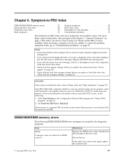
... an incorrect audio response, diagnose the error message first. Chapter 6. the processor is not included with a series of beep codes (see "Hard disk drive jumper settings" on page 7). 2. FRU/Action Replace the SIMM in the socket identified by the diagnostic programs. Error 2xx-1y A memory error was detected in the Configuration/Setup Utility program (see "Power supply" on page 1. Re-run the diagnostic tests or you replace a hard disk drive (see "Beep symptoms" on page 75. v Check the hard disk drive jumper settings before...
... an incorrect audio response, diagnose the error message first. Chapter 6. the processor is not included with a series of beep codes (see "Hard disk drive jumper settings" on page 7). 2. FRU/Action Replace the SIMM in the socket identified by the diagnostic programs. Error 2xx-1y A memory error was detected in the Configuration/Setup Utility program (see "Power supply" on page 1. Re-run the diagnostic tests or you replace a hard disk drive (see "Beep symptoms" on page 75. v Check the hard disk drive jumper settings before...
Hardware Maintenance Manual
Page 46
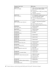
... board 1. System board 1. Run memory test 4. System board 1. System board 1. System board 40 Hardware Maintenance Manual A40 Type 6840 A40P Type 6841 A40i Type 2271: IBM NetVista Computer Make sure the component that is called out is connected and/or enabled 2. No action 1. Flash the system 2. Flash the system 3. Reboot the system 2. Run Setup 2. If a component is called out, make sure it is connected and/or enabled 2. Go to the ″Undetermined problems″ section 2. Replace component under test 1. System board 1. Flash the...
... board 1. System board 1. Run memory test 4. System board 1. System board 1. System board 40 Hardware Maintenance Manual A40 Type 6840 A40P Type 6841 A40i Type 2271: IBM NetVista Computer Make sure the component that is called out is connected and/or enabled 2. No action 1. Flash the system 2. Flash the system 3. Reboot the system 2. Run Setup 2. If a component is called out, make sure it is connected and/or enabled 2. Go to the ″Undetermined problems″ section 2. Replace component under test 1. System board 1. Flash the...

Hardware Maintenance Manual
Page 51
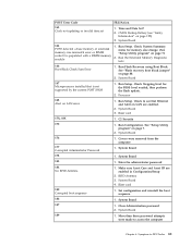
...-test 3. System board 014-000-XXX Parallel port Interface Test Passed 1. Run Setup, enable port 2. Re-start the test, if necessary 011-196-XXX 1. Component that is called out, make sure it is connected and/or enabled 2. Go to review the log file Serial port test halt, error threshold exceeded 2. External serial device 2. Flash the system 3. Press F3 to the ″Undetermined problems″ section 2. Re-run test 3. Component under function test 011-2XX-XXX Serial port signal failure...
...-test 3. System board 014-000-XXX Parallel port Interface Test Passed 1. Run Setup, enable port 2. Re-start the test, if necessary 011-196-XXX 1. Component that is called out, make sure it is connected and/or enabled 2. Go to review the log file Serial port test halt, error threshold exceeded 2. External serial device 2. Flash the system 3. Press F3 to the ″Undetermined problems″ section 2. Re-run test 3. Component under function test 011-2XX-XXX Serial port signal failure...

Hardware Maintenance Manual
Page 52
...-test 3. Replace component under test 1. System board 1. Re-start the test, if necessary 1. Component under function test 1. System board 46 Hardware Maintenance Manual A40 Type 6840 A40P Type 6841 A40i Type 2271: IBM NetVista Computer Diagnostic Error Code 014-001-XXX Parallel port Presence 014-002-XXX 014-003-XXX Parallel port Timeout/Parity error 014-013-XXX 014-014-XXX Parallel port Control Signal/Loopback test failure 014-015-XXX Parallel port External Loopback failure 014-027-XXX Parallel port Configuration/Setup error...
...-test 3. Replace component under test 1. System board 1. Re-start the test, if necessary 1. Component under function test 1. System board 46 Hardware Maintenance Manual A40 Type 6840 A40P Type 6841 A40i Type 2271: IBM NetVista Computer Diagnostic Error Code 014-001-XXX Parallel port Presence 014-002-XXX 014-003-XXX Parallel port Timeout/Parity error 014-013-XXX 014-014-XXX Parallel port Control Signal/Loopback test failure 014-015-XXX Parallel port External Loopback failure 014-027-XXX Parallel port Configuration/Setup error...

Hardware Maintenance Manual
Page 53
... 2. Run memory test 4. System board 1. Press F3 to the ″Undetermined problems″ section 2. Flash the system and re-test 3. Riser card, if installed 2. Diagnostic Error Code 015-002-XXX USB port Timeout 015-015-XXX USB port External Loopback failure 015-027-XXX USB port Configuration/Setup error 015-032-XXX USB port Device Controller failure 015-034-XXX USB port buffer allocation failure 015-035-XXX USB port Reset condition detected 015-036-XXX USB port Register error 015-040-XXX USB port IRQ failure 015-195-XXX USB port Test...
... 2. Run memory test 4. System board 1. Press F3 to the ″Undetermined problems″ section 2. Flash the system and re-test 3. Riser card, if installed 2. Diagnostic Error Code 015-002-XXX USB port Timeout 015-015-XXX USB port External Loopback failure 015-027-XXX USB port Configuration/Setup error 015-032-XXX USB port Device Controller failure 015-034-XXX USB port buffer allocation failure 015-035-XXX USB port Reset condition detected 015-036-XXX USB port Register error 015-040-XXX USB port IRQ failure 015-195-XXX USB port Test...

Hardware Maintenance Manual
Page 55
... test 1. Go to review the log file 2. No action Chapter 6. System board 1. Check power supply 3. Information 2. Component that is called out, make sure it is connected and/or enabled 2. Replace component under function test 1. PCI card 2. IDE device 4. IDE device 4. Re-start the test, if necessary 1. IDE signal cable 2. System board 1. IDE device 4. Flash the system and re-test 3. Flash the system and re-test 3. Re-start the test to the ″Undetermined problems″ section 2. Flash...
... test 1. Go to review the log file 2. No action Chapter 6. System board 1. Check power supply 3. Information 2. Component that is called out, make sure it is connected and/or enabled 2. Replace component under function test 1. PCI card 2. IDE device 4. IDE device 4. Re-start the test, if necessary 1. IDE signal cable 2. System board 1. IDE device 4. Flash the system and re-test 3. Flash the system and re-test 3. Re-start the test to the ″Undetermined problems″ section 2. Flash...

Hardware Maintenance Manual
Page 66
... a device been added, removed, changed location? Diskette Drive Cable 4. Reseat adapters 2. Any adapter 3. Processor 2. System Board 1. Riser card 60 Hardware Maintenance Manual A40 Type 6840 A40P Type 6841 A40i Type 2271: IBM NetVista Computer System Board 1. Riser card 4. Riser card 1. Power-on external devices first, then power-on page 125) System Board 5. System Board 3. Run Setup 2. Run Setup and verify Configuration 2. CMOS Backup Battery (see "Safety Information" on page 125) 3. SCSI Cable 2. L2 Cache Memory 3. System Board 6. SCSI Adapter 1. System Board...
... a device been added, removed, changed location? Diskette Drive Cable 4. Reseat adapters 2. Any adapter 3. Processor 2. System Board 1. Riser card 60 Hardware Maintenance Manual A40 Type 6840 A40P Type 6841 A40i Type 2271: IBM NetVista Computer System Board 1. Riser card 4. Riser card 1. Power-on external devices first, then power-on page 125) System Board 5. System Board 3. Run Setup 2. Run Setup and verify Configuration 2. CMOS Backup Battery (see "Safety Information" on page 125) 3. SCSI Cable 2. L2 Cache Memory 3. System Board 6. SCSI Adapter 1. System Board...
Hardware Maintenance Manual
Page 67
... Board 4. CMOS Backup Battery (see that is populated with a RIMM memory module 1. Processor 168 Alert on LAN are enabled in Configuration/Setup 2. System Board 3. Set configuration and reinstall the boot sequence 186 1. System Board 187 1. Run the Extended Memory Diagnostic tests 166 Boot Block Check Sum Error 1. Riser card 17X, 18X 1. Run Setup. Run Flash Recovery using Boot Block. Check to see "Safety Information" on page 88. 2. System Board 178 1. Enter the administrator password 184 No RFID Antenna 1. Symptom-to access the...
... Board 4. CMOS Backup Battery (see that is populated with a RIMM memory module 1. Processor 168 Alert on LAN are enabled in Configuration/Setup 2. System Board 3. Set configuration and reinstall the boot sequence 186 1. System Board 187 1. Run the Extended Memory Diagnostic tests 166 Boot Block Check Sum Error 1. Riser card 17X, 18X 1. Run Setup. Run Flash Recovery using Boot Block. Check to see "Safety Information" on page 88. 2. System Board 178 1. Enter the administrator password 184 No RFID Antenna 1. Symptom-to access the...

Hardware Maintenance Manual
Page 71
...card 5. Rerun diagnostics. 5. Diskette Drive 2. SCSI Device 2. 16-bit AT Fast SCSU adapter 3. Check cable connections 2. System Board 1. See "Power supply" on page 7.) 1. Possible hard disk drive problem; Display 1. Multiport/2 Adapter Chapter 6. POST Error Code 16XX 1762 Hard disk drive configuration error 1780 (Disk Drive 0) 1781 (Disk Drive 1) 1782 (Disk Drive 2) 1783 (Disk Drive 3) 180X, 188X PCI configuration or resource error 1962 Boot sequence error 209X 20XX Not listed above 21XX 2401, 2402 If screen colors change 2401, 2402 If screen colors are OK 2409 2410 2462 Video memory...
...card 5. Rerun diagnostics. 5. Diskette Drive 2. SCSI Device 2. 16-bit AT Fast SCSU adapter 3. Check cable connections 2. System Board 1. See "Power supply" on page 7.) 1. Possible hard disk drive problem; Display 1. Multiport/2 Adapter Chapter 6. POST Error Code 16XX 1762 Hard disk drive configuration error 1780 (Disk Drive 0) 1781 (Disk Drive 1) 1782 (Disk Drive 2) 1783 (Disk Drive 3) 180X, 188X PCI configuration or resource error 1962 Boot sequence error 209X 20XX Not listed above 21XX 2401, 2402 If screen colors change 2401, 2402 If screen colors are OK 2409 2410 2462 Video memory...

Hardware Maintenance Manual
Page 91
... hardware and software-related passwords. The system senses the change in the Setup Utility program. v Power-on Password v Administrator Password v Operating System Password Power-on password denies access to find the recovery jumper. 3. Removing a power-on password To service a computer with an active and unknown power-on . Refer to "A40/A40P/A40i system board layout" on page 29 to the computer by an unauthorized user when the computer is necessary to move the jumper back to clear...
... hardware and software-related passwords. The system senses the change in the Setup Utility program. v Power-on Password v Administrator Password v Operating System Password Power-on password denies access to find the recovery jumper. 3. Removing a power-on password To service a computer with an active and unknown power-on . Refer to "A40/A40P/A40i system board layout" on page 29 to the computer by an unauthorized user when the computer is necessary to move the jumper back to clear...
Hardware Maintenance Manual
Page 137
... check and repair hard disk data allocation errors. Chapter 10. Related Service Information 131 However, it is working Use the test programs that come with this HMM to set up and start devices. Also, from the DOS prompt or from OS/2 Utilities, use .INI files to resolve the problem. v POST error messages are five types of the hardware. Not all device drivers are text messages. Basically, there are displayed when...
... check and repair hard disk data allocation errors. Chapter 10. Related Service Information 131 However, it is working Use the test programs that come with this HMM to set up and start devices. Also, from the DOS prompt or from OS/2 Utilities, use .INI files to resolve the problem. v POST error messages are five types of the hardware. Not all device drivers are text messages. Basically, there are displayed when...


