
Installation Guide
Page 5
... and Mouse (When Using a Graphics Display 8 Step 12. Connect the Adapter Cables 10 Step 14. Start Your Model 275 15 Step 21. Need Help 3 Step 3. Adjust the Stability Feet 5 Step 8. Check Your Inventory 1 IntelliStation POWER 9114 Model 275 1 Step 2. Install the Rear Acoustical Cover 13 Step 17. Setting Up the System 1 Step 1. Run System Verification...
... and Mouse (When Using a Graphics Display 8 Step 12. Connect the Adapter Cables 10 Step 14. Start Your Model 275 15 Step 21. Need Help 3 Step 3. Adjust the Stability Feet 5 Step 8. Check Your Inventory 1 IntelliStation POWER 9114 Model 275 1 Step 2. Install the Rear Acoustical Cover 13 Step 17. Setting Up the System 1 Step 1. Run System Verification...

Installation Guide
Page 6
... Devices 24 Options and Task List 24 Stopping the System 25 Starting the System 25 Placing the Model 275 into the Service and Operating Position 26 Bezel Door 26 Bezel Door Removal 26 Bezel Door Replacement 26 ...Tray Assembly 35 Removing the Fan Tray Assembly 35 Replacing the Fan Tray Assembly 37 Power Supply 38 Power Supply Removal 38 Power Supply Replacement 40 Installing a Power Supply 41 Media Drives (Diskette, CD-ROM, DVD-ROM, Tape, or Disk ... Service Processor Assembly 57 Replacing the Service Processor Assembly 57 iv IntelliStation POWER 9114 Model 275 Installation Guide
... Devices 24 Options and Task List 24 Stopping the System 25 Starting the System 25 Placing the Model 275 into the Service and Operating Position 26 Bezel Door 26 Bezel Door Removal 26 Bezel Door Replacement 26 ...Tray Assembly 35 Removing the Fan Tray Assembly 35 Replacing the Fan Tray Assembly 37 Power Supply 38 Power Supply Removal 38 Power Supply Replacement 40 Installing a Power Supply 41 Media Drives (Diskette, CD-ROM, DVD-ROM, Tape, or Disk ... Service Processor Assembly 57 Replacing the Service Processor Assembly 57 iv IntelliStation POWER 9114 Model 275 Installation Guide

Installation Guide
Page 10
D01 viii IntelliStation POWER 9114 Model 275 Installation Guide DANGER To prevent electrical shock hazard, disconnect all power cables from the electrical outlet before relocating the system.
D01 viii IntelliStation POWER 9114 Model 275 Installation Guide DANGER To prevent electrical shock hazard, disconnect all power cables from the electrical outlet before relocating the system.

Installation Guide
Page 15
... AIX and pSeries accessibility. v The RS/6000 pSeries Diagnostic Information for the IBM pSeries is available online. v To access the pSeries publications, click Hardware documentation. About This Book This book provides information about your system unit: v The IntelliStation POWER 9114 Model 275 User's Guide, order number SA38-0635, contains information to help users use the...
... AIX and pSeries accessibility. v The RS/6000 pSeries Diagnostic Information for the IBM pSeries is available online. v To access the pSeries publications, click Hardware documentation. About This Book This book provides information about your system unit: v The IntelliStation POWER 9114 Model 275 User's Guide, order number SA38-0635, contains information to help users use the...

Installation Guide
Page 16
... order number SA38-0516, contains information about adapters, devices, and cables for your workstation and to avoid discomfort. xiv IntelliStation POWER 9114 Model 275 Installation Guide v The System Unit Safety Information, order number SA23-2652, contains translations of International Business Machines Corporation in ... and service names may be arranged to suit your installation. Good ergonomic practice is : http://www.us.pc.ibm.com/healthycomputing Trademarks The following terms are trademarks of safety information used in the RS/6000 pSeries Eserver Diagnostic Information...
... order number SA38-0516, contains information about adapters, devices, and cables for your workstation and to avoid discomfort. xiv IntelliStation POWER 9114 Model 275 Installation Guide v The System Unit Safety Information, order number SA23-2652, contains translations of International Business Machines Corporation in ... and service names may be arranged to suit your installation. Good ergonomic practice is : http://www.us.pc.ibm.com/healthycomputing Trademarks The following terms are trademarks of safety information used in the RS/6000 pSeries Eserver Diagnostic Information...

Installation Guide
Page 17
Check Your Inventory IntelliStation POWER 9114 Model 275 h Books, CD-ROM and Other Media h ″About Your Machine″ Document h Power Cables (1 standard, 2 optional) h 9-Pin to 25-Pin Serial Converters (2) (optional) h ASCII Terminal (optional) 1 Setting Up the System To set up your system, follow the procedures in this chapter. Step 1. Chapter 1.
Check Your Inventory IntelliStation POWER 9114 Model 275 h Books, CD-ROM and Other Media h ″About Your Machine″ Document h Power Cables (1 standard, 2 optional) h 9-Pin to 25-Pin Serial Converters (2) (optional) h ASCII Terminal (optional) 1 Setting Up the System To set up your system, follow the procedures in this chapter. Step 1. Chapter 1.

Installation Guide
Page 18
h Display, Cable (optional), and Cable Toroid (optional) h Keyboard (optional), Wrist/Palm Rest (optional) h Mouse (optional) h Power-On Guard hModel 275 2 IntelliStation POWER 9114 Model 275 Installation Guide Inventory table continued from the previous page.
h Display, Cable (optional), and Cable Toroid (optional) h Keyboard (optional), Wrist/Palm Rest (optional) h Mouse (optional) h Power-On Guard hModel 275 2 IntelliStation POWER 9114 Model 275 Installation Guide Inventory table continued from the previous page.

Installation Guide
Page 20
... your workstation, visit the Healthy Computing Web address at the rear of the system unit and 152 mm (6 inches) at : http://www.pc.ibm.com/us/healthycomputing. For more information on the sides of the system unit to allow the system unit to the system unit. v Place the... safely and easily complete the setup procedures. Blocking the air vents can cause overheating, which might result in a stable and sturdy location. 4 IntelliStation POWER 9114 Model 275 Installation Guide The front of the system requires a minimum of 76 mm (3 inches) of the Internal Options Installed? Step 4.
... your workstation, visit the Healthy Computing Web address at the rear of the system unit and 152 mm (6 inches) at : http://www.pc.ibm.com/us/healthycomputing. For more information on the sides of the system unit to allow the system unit to the system unit. v Place the... safely and easily complete the setup procedures. Blocking the air vents can cause overheating, which might result in a stable and sturdy location. 4 IntelliStation POWER 9114 Model 275 Installation Guide The front of the system requires a minimum of 76 mm (3 inches) of the Internal Options Installed? Step 4.

Installation Guide
Page 22
Attach the Display Cable Toroid If the cable for your display does not include a toroid, locate the toroid shipped with your system and follow the installation instructions included with the toroid. 1 Display Cable Toroid 6 IntelliStation POWER 9114 Model 275 Installation Guide Step 9.
Attach the Display Cable Toroid If the cable for your display does not include a toroid, locate the toroid shipped with your system and follow the installation instructions included with the toroid. 1 Display Cable Toroid 6 IntelliStation POWER 9114 Model 275 Installation Guide Step 9.

Installation Guide
Page 24
Step 11. Read the Safety Notices" on the rear of the system unit. 8 IntelliStation POWER 9114 Model 275 Installation Guide As shown in the following illustration, connect the keyboard and mouse to the keyboard documentation for installation instructions. If a wrist or palm rest was included with your keyboard and you want to attach it, refer to the connectors on page 3. Connect the Keyboard and Mouse (When Using a Graphics Display) Note: Before doing this step, read and understand "Step 3.
Step 11. Read the Safety Notices" on the rear of the system unit. 8 IntelliStation POWER 9114 Model 275 Installation Guide As shown in the following illustration, connect the keyboard and mouse to the keyboard documentation for installation instructions. If a wrist or palm rest was included with your keyboard and you want to attach it, refer to the connectors on page 3. Connect the Keyboard and Mouse (When Using a Graphics Display) Note: Before doing this step, read and understand "Step 3.

Installation Guide
Page 26
... applications (interface cable required), ASCII Terminal for AIX Console, and Modems Service Processor menus, HACMP, ASCII Terminal for AIX Console, and Modems HACMP, UPS (uninterruptible power supply), ASCII Terminal for the serial port connectors is as token ring or 8-port EIA-232), connect the cables to serial port S2. If you... 2 (S2) Rear of the System Serial Port 3 (S3) Rear of the System Examples of installed adapters, consult the ″About Your Machine″ document. 10 IntelliStation POWER 9114 Model 275 Installation Guide
... applications (interface cable required), ASCII Terminal for AIX Console, and Modems Service Processor menus, HACMP, ASCII Terminal for AIX Console, and Modems HACMP, UPS (uninterruptible power supply), ASCII Terminal for the serial port connectors is as token ring or 8-port EIA-232), connect the cables to serial port S2. If you... 2 (S2) Rear of the System Serial Port 3 (S3) Rear of the System Examples of installed adapters, consult the ″About Your Machine″ document. 10 IntelliStation POWER 9114 Model 275 Installation Guide

Installation Guide
Page 28
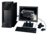
..., and attached devices. Use this power cable with one power supply, connect the power cable to the system drawer. Each power supply needs its own power cable. 2. If your system is equipped with two power supplies. C01 12 IntelliStation POWER 9114 Model 275 Installation Guide Step 15. Notes: 1. A second power receptacle is present when a second (redundant) power supply has been added to...
..., and attached devices. Use this power cable with one power supply, connect the power cable to the system drawer. Each power supply needs its own power cable. 2. If your system is equipped with two power supplies. C01 12 IntelliStation POWER 9114 Model 275 Installation Guide Step 15. Notes: 1. A second power receptacle is present when a second (redundant) power supply has been added to...
Installation Guide
Page 30
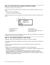
...to "Step 20. The indicators of the following illustration shows the operator panel in standby mode with the software. 14 IntelliStation POWER 9114 Model 275 Installation Guide For information about installing AIX from a Network Installation Management (NIM) server. v OK is Now Set Up.... For other software installation, refer to the system unit. On the IntelliStation POWER 9114 Model 275, the CD-ROM drive is slowly blinking. Connect the Power Cables to Electrical Outlets Connect the power source to the documentation provided with OK visible in the operator panel display...
...to "Step 20. The indicators of the following illustration shows the operator panel in standby mode with the software. 14 IntelliStation POWER 9114 Model 275 Installation Guide For information about installing AIX from a Network Installation Management (NIM) server. v OK is Now Set Up.... For other software installation, refer to the system unit. On the IntelliStation POWER 9114 Model 275, the CD-ROM drive is slowly blinking. Connect the Power Cables to Electrical Outlets Connect the power source to the documentation provided with OK visible in the operator panel display...

Installation Guide
Page 32
...management and end-user documentation. 16 IntelliStation POWER 9114 Model 275 Installation Guide Ensure that the system administrator reads the following information and is available from the IBM pSeries Information Eserver Center at Eserver http://publib16.boulder.ibm.com/pseries/en_US/infocenter/base. Select... AIX Documentation CD contains the base set of the options to test your service representative. Step 22. Hardware Documentation IBM pSeries hardware publications are installing this system and another person is the system administrator, deliver this book to Chapter 2,...
...management and end-user documentation. 16 IntelliStation POWER 9114 Model 275 Installation Guide Ensure that the system administrator reads the following information and is available from the IBM pSeries Information Eserver Center at Eserver http://publib16.boulder.ibm.com/pseries/en_US/infocenter/base. Select... AIX Documentation CD contains the base set of the options to test your service representative. Step 22. Hardware Documentation IBM pSeries hardware publications are installing this system and another person is the system administrator, deliver this book to Chapter 2,...
Installation Guide
Page 34
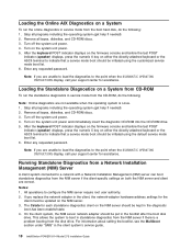
... password. On the client system, the NIM server network adapter should be put in the client system's service guide. 18 IntelliStation POWER 9114 Model 275 Installation Guide Notes: 1. Stop all programs including the operating system (get help if needed ). 2. Turn off the system unit... power. 4. Note: If you are correct. Stop all programs including the operating system (get help if needed ). 2. Loading the Online AIX...
... password. On the client system, the NIM server network adapter should be put in the client system's service guide. 18 IntelliStation POWER 9114 Model 275 Installation Guide Notes: 1. Stop all programs including the operating system (get help if needed ). 2. Turn off the system unit... power. 4. Note: If you are correct. Stop all programs including the operating system (get help if needed ). 2. Loading the Online AIX...
Installation Guide
Page 36
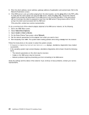
If the ping fails, contact your service representative. 20 IntelliStation POWER 9114 Model 275 Installation Guide Exit completely from SMS. The system starts loading packets while doing a bootp from the client system, use the ping utility in the RIPL ...
If the ping fails, contact your service representative. 20 IntelliStation POWER 9114 Model 275 Installation Guide Exit completely from SMS. The system starts loading packets while doing a bootp from the client system, use the ping utility in the RIPL ...

Installation Guide
Page 38
...Access the System Documentation If you have access to CORE, do the following sources: v Web site: http://techsupport.services.ibm.com/server/mdownload2/download.html From the Web site, follow the instructions for checking your system's firmware level and for the...Documentation Documentation for the operating system, including system-management and end-user documentation. 22 IntelliStation POWER 9114 Model 275 Installation Guide v To view information about the accessibility features of publications for the IBM pSeries is available from this Web site. RS/6000 3. RS/6000 - The ...
...Access the System Documentation If you have access to CORE, do the following sources: v Web site: http://techsupport.services.ibm.com/server/mdownload2/download.html From the Web site, follow the instructions for checking your system's firmware level and for the...Documentation Documentation for the operating system, including system-management and end-user documentation. 22 IntelliStation POWER 9114 Model 275 Installation Guide v To view information about the accessibility features of publications for the IBM pSeries is available from this Web site. RS/6000 3. RS/6000 - The ...

Installation Guide
Page 40
...and disk drives are sensitive to lay the device down while it is out of the antistatic bag, lay it on page 25 24 IntelliStation POWER 9114 Model 275 Installation Guide v Grasp cards and boards by the frame. Options and Task List The following precautions: v If you are wrapped in the... Drives Disk Drive Backplane Disk Drive Bezels and Fillers Hot-Swap System Fans Fan Tray Assembly Media Drives Media Bay Chassis Memory DIMMs Power Supply Service Processor Assembly Starting the System Static-Sensitive Devices Stopping the System Option/Task Name and Page Location "PCI Adapters" on ...
...and disk drives are sensitive to lay the device down while it is out of the antistatic bag, lay it on page 25 24 IntelliStation POWER 9114 Model 275 Installation Guide v Grasp cards and boards by the frame. Options and Task List The following precautions: v If you are wrapped in the... Drives Disk Drive Backplane Disk Drive Bezels and Fillers Hot-Swap System Fans Fan Tray Assembly Media Drives Media Bay Chassis Memory DIMMs Power Supply Service Processor Assembly Starting the System Static-Sensitive Devices Stopping the System Option/Task Name and Page Location "PCI Adapters" on ...

Installation Guide
Page 42
...door forward, out past the bottom of the system. 4. Bezel Door The following : 1. Swing the bezel door away from the bezel. 1 Model 275 2 System Handle Assembly Post Retaining Hole 3 Bezel Door Top Retaining Post 4 Bezel Door 5 Bezel Door Handle 6 Bezel Door Release Tab 7 Bezel ... preceding illustration. 2. Lift the bezel door release tab located at the bottom of the system unit. Close the bezel door. 26 IntelliStation POWER 9114 Model 275 Installation Guide Bezel Door Removal Refer to clear the post. 3. Open the bezel door by grasping the door handle. When finished working...
...door forward, out past the bottom of the system. 4. Bezel Door The following : 1. Swing the bezel door away from the bezel. 1 Model 275 2 System Handle Assembly Post Retaining Hole 3 Bezel Door Top Retaining Post 4 Bezel Door 5 Bezel Door Handle 6 Bezel Door Release Tab 7 Bezel ... preceding illustration. 2. Lift the bezel door release tab located at the bottom of the system unit. Close the bezel door. 26 IntelliStation POWER 9114 Model 275 Installation Guide Bezel Door Removal Refer to clear the post. 3. Open the bezel door by grasping the door handle. When finished working...

Installation Guide
Page 44
Operating the system for thumbscrew locations. 2. Align the service access cover with the cover removed might damage system components. 1 Model 275 2 Front Chassis Ledge 3 Service Access Cover 4 Thumbscrews Service Access Cover Replacement To replace the service access cover, do the following ... replace the cover before turning on the top and bottom of the system drawer. The front edge of the cover. 28 IntelliStation POWER 9114 Model 275 Installation Guide Loosen the two captive thumbscrews located on page vii. After the front of the cover. Covers Before performing the ...
Operating the system for thumbscrew locations. 2. Align the service access cover with the cover removed might damage system components. 1 Model 275 2 Front Chassis Ledge 3 Service Access Cover 4 Thumbscrews Service Access Cover Replacement To replace the service access cover, do the following ... replace the cover before turning on the top and bottom of the system drawer. The front edge of the cover. 28 IntelliStation POWER 9114 Model 275 Installation Guide Loosen the two captive thumbscrews located on page vii. After the front of the cover. Covers Before performing the ...

