
Hardware Maintenance Manual
Page 7
...55 Processor board LEDs 55 Processor board connectors 56 Processor board jumpers 57 Memory board component locations 58 Memory board connectors 58 Memory board LED locations 60 Before you begin 60 Working inside the server with the power on . . . . . 61 Removing the server top cover and bezel 61 Removing the top cover 62 Removing the media-bay bezel 62 Removing the front trim bezel 63 Working with adapters 63 Adapter considerations 64 Installing a hot-plug adapter 64 Installing internal drives 66 Internal drive bays 67 Installing a hot-swap hard disk drive 68 Installing a 5.25...
...55 Processor board LEDs 55 Processor board connectors 56 Processor board jumpers 57 Memory board component locations 58 Memory board connectors 58 Memory board LED locations 60 Before you begin 60 Working inside the server with the power on . . . . . 61 Removing the server top cover and bezel 61 Removing the top cover 62 Removing the media-bay bezel 62 Removing the front trim bezel 63 Working with adapters 63 Adapter considerations 64 Installing a hot-plug adapter 64 Installing internal drives 66 Internal drive bays 67 Installing a hot-swap hard disk drive 68 Installing a 5.25...

Hardware Maintenance Manual
Page 8
...Manager 120 Remote Workstation Control 120 Screen View 120 Security Manager 120 Serial Connection Control 120 Service Configuration Manager 120 Software Inventory 121 System Diagnostics Manager 121 System Information Tool 121 System Monitor 121 System Partition Access 121 System Profile 121 Update Connector Manager 121 Web Manager Configuration 122 FRU information (service only 127 Diagnostic switch card 127 Disconnecting the shuttle 128 Front LED card assembly 128 I/O Legacy board 129 Memory card removal 130 PCI switch card 132 Power backplane assembly 132 Processor/PCI...
...Manager 120 Remote Workstation Control 120 Screen View 120 Security Manager 120 Serial Connection Control 120 Service Configuration Manager 120 Software Inventory 121 System Diagnostics Manager 121 System Information Tool 121 System Monitor 121 System Partition Access 121 System Profile 121 Update Connector Manager 121 Web Manager Configuration 122 FRU information (service only 127 Diagnostic switch card 127 Disconnecting the shuttle 128 Front LED card assembly 128 I/O Legacy board 129 Memory card removal 130 PCI switch card 132 Power backplane assembly 132 Processor/PCI...

Hardware Maintenance Manual
Page 9
... Supported RAID levels 193 Drive state descriptions 202 Acronyms, terms, and definitions 210 Symptom-to-FRU index 215 Beep symptoms 215 No beep symptoms 218 Diagnostic panel LEDs 218 Diagnostic error codes 220 Error symptoms 225 Power supply LED errors 225 POST error codes 226 ServeRAID POST (ISPR) error codes 232 ServeRAID POST (ISPR) error procedures 232 ServeRAID 234 SCSI error codes 236 Temperature error messages 236 Fan error messages 237 Power error messages 237 System shutdown 238 Power...
... Supported RAID levels 193 Drive state descriptions 202 Acronyms, terms, and definitions 210 Symptom-to-FRU index 215 Beep symptoms 215 No beep symptoms 218 Diagnostic panel LEDs 218 Diagnostic error codes 220 Error symptoms 225 Power supply LED errors 225 POST error codes 226 ServeRAID POST (ISPR) error codes 232 ServeRAID POST (ISPR) error procedures 232 ServeRAID 234 SCSI error codes 236 Temperature error messages 236 Fan error messages 237 Power error messages 237 System shutdown 238 Power...

Hardware Maintenance Manual
Page 16
...-plug PCI adapters • Error codes and messages • System error logging • Upgradable BIOS, diagnostics, and code • Automatic restart after a power failure • Parity checking on processors, processor board, I/O board, power supplies, hard disk backplane, power backplane and VRMs. • Information and diagnostic LED panels 6 Hardware Maintenance Manual: Netfinity 7600 - The controller provides full-duplex (FDX) capability, which enables simultaneous transmission and reception of data on the Ethernet local area network (LAN). • Redundant network-interface card...
...-plug PCI adapters • Error codes and messages • System error logging • Upgradable BIOS, diagnostics, and code • Automatic restart after a power failure • Parity checking on processors, processor board, I/O board, power supplies, hard disk backplane, power backplane and VRMs. • Information and diagnostic LED panels 6 Hardware Maintenance Manual: Netfinity 7600 - The controller provides full-duplex (FDX) capability, which enables simultaneous transmission and reception of data on the Ethernet local area network (LAN). • Redundant network-interface card...

Hardware Maintenance Manual
Page 18
... feature is enabled in the Configuration/Setup utility program, the wake-up feature will turn on the server by pressing the Power Control button on , a power failure occurs, and unattended- Watch for the System Power light on the operator information panel to stop blinking. 8 Hardware Maintenance Manual: Netfinity 7600 - During this time the system-management processor is initializing and the Power Control button does not respond. • If the server is supported by your system to stop running. Note: Wait...
... feature is enabled in the Configuration/Setup utility program, the wake-up feature will turn on the server by pressing the Power Control button on , a power failure occurs, and unattended- Watch for the System Power light on the operator information panel to stop blinking. 8 Hardware Maintenance Manual: Netfinity 7600 - During this time the system-management processor is initializing and the Power Control button does not respond. • If the server is supported by your system to stop running. Note: Wait...

Hardware Maintenance Manual
Page 40
... hard disk drives is removed. 1. If the problem persists, replace the VRM. The system temperature has exceeded the maximum rating. 1. Check to operate in PCI slot 1 or 2, or the processor board 1. If the problem persists, see "Temperature checkout" on PCI bus A. Either add a power supply or remove a device from PCI bus B (PCI slots 3-6) and restarting the server after each adapter is removed. Replace the third power supply. 30 Hardware Maintenance Manual: Netfinity 7600 - None LED SMI NMI Cause Action The system error log is installed...
... hard disk drives is removed. 1. If the problem persists, replace the VRM. The system temperature has exceeded the maximum rating. 1. Check to operate in PCI slot 1 or 2, or the processor board 1. If the problem persists, see "Temperature checkout" on PCI bus A. Either add a power supply or remove a device from PCI bus B (PCI slots 3-6) and restarting the server after each adapter is removed. Replace the third power supply. 30 Hardware Maintenance Manual: Netfinity 7600 - None LED SMI NMI Cause Action The system error log is installed...

Hardware Maintenance Manual
Page 45
... PCI device. If the Ethernet Transmit/Receive Activity light is also assigned to another device in the Configuration/Setup Utility program. Ethernet controller troubleshooting chart You can use a crossover cable. Diagnostics 35 These lights indicate whether a problem exists with the hub. - The Ethernet Link Status light illuminates when the Ethernet controller receives a LINK pulse from the World Wide Web. • Run the network diagnostic program. The Ethernet Transmit/Receive Activity light illuminates when the Ethernet controller sends...
... PCI device. If the Ethernet Transmit/Receive Activity light is also assigned to another device in the Configuration/Setup Utility program. Ethernet controller troubleshooting chart You can use a crossover cable. Diagnostics 35 These lights indicate whether a problem exists with the hub. - The Ethernet Link Status light illuminates when the Ethernet controller receives a LINK pulse from the World Wide Web. • Run the network diagnostic program. The Ethernet Transmit/Receive Activity light illuminates when the Ethernet controller sends...

Hardware Maintenance Manual
Page 46
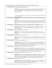
... Ethernet controller stopped working when another device in the Configuration/Setup Utility program. Type 8665 Models 1RY, 2RY Table 2. If necessary, remove any LED parameter settings when you have loaded the network device drivers. • The network might display messages from this workstation. • Run diagnostics on the hub. • If the hub does not support auto-negotiation, manually configure the Ethernet controller to or by this LED can be idle. Check the following device drivers: 36 Hardware Maintenance Manual: Netfinity 7600 - A crossover cable...
... Ethernet controller stopped working when another device in the Configuration/Setup Utility program. Type 8665 Models 1RY, 2RY Table 2. If necessary, remove any LED parameter settings when you have loaded the network device drivers. • The network might display messages from this workstation. • Run diagnostics on the hub. • If the hub does not support auto-negotiation, manually configure the Ethernet controller to or by this LED can be idle. Check the following device drivers: 36 Hardware Maintenance Manual: Netfinity 7600 - A crossover cable...
Hardware Maintenance Manual
Page 48
... bit set . If the problem persists, go to "Starting the diagnostic programs" on page 25 to load a new frame type for the Ethernet controller. Explanation: You tried to run the diagnostic programs. 38 Hardware Maintenance Manual: Netfinity 7600 - Action: None necessary, message is enabled. Action: Verify that your hardware configuration matches the software settings. Explanation: An error occurred while the driver was made in the node address override was set . Restart the server. Table...
... bit set . If the problem persists, go to "Starting the diagnostic programs" on page 25 to load a new frame type for the Ethernet controller. Explanation: You tried to run the diagnostic programs. 38 Hardware Maintenance Manual: Netfinity 7600 - Action: None necessary, message is enabled. Action: Verify that your hardware configuration matches the software settings. Explanation: An error occurred while the driver was made in the node address override was set . Restart the server. Table...

Hardware Maintenance Manual
Page 50
... the Ethernet controller is enabled, run the diagnostic programs. Cannot allocate memory for the adapter during an interrupt. Action: Verify that additional IBM Netfinity 10/100 Fault Tolerant Adapters are present or replace the Ethernet adapter that the Ethernet controller is enabled, run the diagnostic programs. Device failed checksum test! If the problem persists, run the NETCONFIG program to increase the number of Streams memory blocks. Otherwise, run the diagnostic programs. IRQ found for another Ethernet controller •...
... the Ethernet controller is enabled, run the diagnostic programs. Cannot allocate memory for the adapter during an interrupt. Action: Verify that additional IBM Netfinity 10/100 Fault Tolerant Adapters are present or replace the Ethernet adapter that the Ethernet controller is enabled, run the diagnostic programs. Device failed checksum test! If the problem persists, run the NETCONFIG program to increase the number of Streams memory blocks. Otherwise, run the diagnostic programs. IRQ found for another Ethernet controller •...

Hardware Maintenance Manual
Page 55
... System Management Processor clock time, leave the value set passwords or a system owner's name. See"Using passwords" on the Configuration/Setup Utility main menu. System Owner's Name Select this choice to set at its default of 0. • System Security Select this choice to specify a system owner's name, which will display during POST. You can set or change an administrator password. You can use any combination of password protection: - You must replace the I /O Ports...
... System Management Processor clock time, leave the value set passwords or a system owner's name. See"Using passwords" on the Configuration/Setup Utility main menu. System Owner's Name Select this choice to set at its default of 0. • System Security Select this choice to specify a system owner's name, which will display during POST. You can set or change an administrator password. You can use any combination of password protection: - You must replace the I /O Ports...

Hardware Maintenance Manual
Page 59
... Configuration/Setup Utility main menu. Follow the instructions on a SCSI hard disk The following sections provide the instructions needed to change the settings of the menu choices available. Using the SCSISelect utility program SCSISelect is required to start the SCSISelect Utility program. 3. When the > prompt appears, press Ctrl+A. then, press Enter. You can enter either channel A (external) or channel B (internal). 4. Note: If the server has a RAID adapter installed, use the configuration method supplied with the RAID adapter to a limited set...
... Configuration/Setup Utility main menu. Follow the instructions on a SCSI hard disk The following sections provide the instructions needed to change the settings of the menu choices available. Using the SCSISelect utility program SCSISelect is required to start the SCSISelect Utility program. 3. When the > prompt appears, press Ctrl+A. then, press Enter. You can enter either channel A (external) or channel B (internal). 4. Note: If the server has a RAID adapter installed, use the configuration method supplied with the RAID adapter to a limited set...

Hardware Maintenance Manual
Page 86
... can connect the cable-management arm after installing the power supply. 76 Hardware Maintenance Manual: Netfinity 7600 - Carefully close the latches to "Completing the installation" on the server; Center the VRM over the microprocessor connector. If you have either a power supply or filler panel installed for that microprocessor. Type 8665 Models 1RY, 2RY Carefully close the latches. If you suspect a problem with the power supply-installation procedure, review the following label attached. Installing a hot-swap power supply CAUTION: Never remove the cover...
... can connect the cable-management arm after installing the power supply. 76 Hardware Maintenance Manual: Netfinity 7600 - Carefully close the latches to "Completing the installation" on the server; Center the VRM over the microprocessor connector. If you have either a power supply or filler panel installed for that microprocessor. Type 8665 Models 1RY, 2RY Carefully close the latches. If you suspect a problem with the power supply-installation procedure, review the following label attached. Installing a hot-swap power supply CAUTION: Never remove the cover...

Hardware Maintenance Manual
Page 99
... the redundant (secondary) controller. If you can be Category 5 or higher. The Ethernet controller is an optional redundant network interface card (NIC adapter) that the cabling in the server. The switch back to the primary Ethernet controller. Failover for the USB-port connectors on the setup and operating system. Table 16. The following table shows the pin-number assignments for redundant Ethernet The IBM Netfinity 10/100 Fault Tolerant Adapter is a PCI Plug and Play device.
... the redundant (secondary) controller. If you can be Category 5 or higher. The Ethernet controller is an optional redundant network interface card (NIC adapter) that the cabling in the server. The switch back to the primary Ethernet controller. Failover for the USB-port connectors on the setup and operating system. Table 16. The following table shows the pin-number assignments for redundant Ethernet The IBM Netfinity 10/100 Fault Tolerant Adapter is a PCI Plug and Play device.

Hardware Maintenance Manual
Page 110
... is an easy to use resource management and planning tool for Netfinity Manager. Type 8665 Models 1RY, 2RY Use Remote Workstation Control to monitor and manage IBM Advanced System Management processors and adapters. Use this system. 7. Capacity Management is only one installation configuration for network managers and administrators, allowing remote performance monitoring of this server library. • Capacity Manager Click Capacity Management to install the Capacity Management service on this service to monitor or control the screen display of Serial Connection Control.
... is an easy to use resource management and planning tool for Netfinity Manager. Type 8665 Models 1RY, 2RY Use Remote Workstation Control to monitor and manage IBM Advanced System Management processors and adapters. Use this system. 7. Capacity Management is only one installation configuration for network managers and administrators, allowing remote performance monitoring of this server library. • Capacity Manager Click Capacity Management to install the Capacity Management service on this service to monitor or control the screen display of Serial Connection Control.

Hardware Maintenance Manual
Page 111
...; Serial Connection Control • Service Configuration Manager • Service Processor Manager • Service Manager • Software Inventory • System Diagnostics Manager • System Information Tool • System Monitor • System Partition Access (requires System Partition) • Update Connector Manager (available only on systems running Windows NT 4.0 or later) • System Profile • Web Manager Configuration (installed only if the Netfinity Manager Installation with Web Enhancement installation configuration is being installed on client systems using...
...; Serial Connection Control • Service Configuration Manager • Service Processor Manager • Service Manager • Software Inventory • System Diagnostics Manager • System Information Tool • System Monitor • System Partition Access (requires System Partition) • Update Connector Manager (available only on systems running Windows NT 4.0 or later) • System Profile • Web Manager Configuration (installed only if the Netfinity Manager Installation with Web Enhancement installation configuration is being installed on client systems using...

Hardware Maintenance Manual
Page 162
.... In Information mode, you start the ServeRAID Manager program, do the following opens. 152 Hardware Maintenance Manual: Netfinity 7600 - Type 8665 Models 1RY, 2RY In startable-CD mode, you can also change specific ServeRAID controller settings after you can configure your ServeRAID controllers. See "Using Information mode" on the server; One of the ServeRAID Manager program and its capabilities. When this mode is available from the menu and tool bars. Insert the IBM ServeRAID Support CD (or...
.... In Information mode, you start the ServeRAID Manager program, do the following opens. 152 Hardware Maintenance Manual: Netfinity 7600 - Type 8665 Models 1RY, 2RY In startable-CD mode, you can also change specific ServeRAID controller settings after you can configure your ServeRAID controllers. See "Using Information mode" on the server; One of the ServeRAID Manager program and its capabilities. When this mode is available from the menu and tool bars. Insert the IBM ServeRAID Support CD (or...

Hardware Maintenance Manual
Page 238
...If the server does not have the latest level of BIOS installed, 2. Disconnect external cable on page 47.) 2. Type 8665 Models 1RY, 2RY Memory card the diagnostic program again. 4. Run Configuration/Setup, if disabled by user or system, see "Memory 1. Keyboard 2. I /O Legacy board 662 (Diskette drive configuration error) 1. Diskette Drive 3. Run Configuration/Setup utility 2. Disabled DIMM, if not disabled by user 1. Processor/PCI Board 301 (Keyboard or keyboard controller error) 1. Keyboard 602 (Invalid diskette boot record) 1. Run Configuration/Setup and...
...If the server does not have the latest level of BIOS installed, 2. Disconnect external cable on page 47.) 2. Type 8665 Models 1RY, 2RY Memory card the diagnostic program again. 4. Run Configuration/Setup, if disabled by user or system, see "Memory 1. Keyboard 2. I /O Legacy board 662 (Diskette drive configuration error) 1. Diskette Drive 3. Run Configuration/Setup utility 2. Disabled DIMM, if not disabled by user 1. Processor/PCI Board 301 (Keyboard or keyboard controller error) 1. Keyboard 602 (Invalid diskette boot record) 1. Run Configuration/Setup and...

Hardware Maintenance Manual
Page 242
... 3 01298104 processor 4) (Bad update data for more information. 3. Processor 4 I9990301 (Fixed boot sector error) 1. SCSI Backplane 4. operating system installed) I9990650 restored) (AC power has been 1. Use these procedures to the PCI slots. EF10 (Default ISPR) 1. No ISPR Error Present. 1XXX (Microcode Checksum Error) 1. Install two download jumpers parallel to help you solve ServeRAID problems when servicing the computer. For jumper locations, see "Processor board component locations" on page 55. 232 Hardware Maintenance Manual: Netfinity 7600 - Type 8665 Models 1RY...
... 3 01298104 processor 4) (Bad update data for more information. 3. Processor 4 I9990301 (Fixed boot sector error) 1. SCSI Backplane 4. operating system installed) I9990650 restored) (AC power has been 1. Use these procedures to the PCI slots. EF10 (Default ISPR) 1. No ISPR Error Present. 1XXX (Microcode Checksum Error) 1. Install two download jumpers parallel to help you solve ServeRAID problems when servicing the computer. For jumper locations, see "Processor board component locations" on page 55. 232 Hardware Maintenance Manual: Netfinity 7600 - Type 8665 Models 1RY...
Hardware Maintenance Manual
Page 244
... Hardware Maintenance Manual: Netfinity 7600 - Installing and configuring ServeRAID controllers," on page 55 for ISPR indicating that there is eliminated: a. then remove the jumpers. 3. If error persists after step 2, replace the controller or the system board with the jumpers in their default locations. Identify which channel is functioning properly. 3. Check termination of identified channel in step a.. Controller is no ISPR error present.) EFFE (Firmware code corrupted or download jumpers are in place; b. and reboot...
... Hardware Maintenance Manual: Netfinity 7600 - Installing and configuring ServeRAID controllers," on page 55 for ISPR indicating that there is eliminated: a. then remove the jumpers. 3. If error persists after step 2, replace the controller or the system board with the jumpers in their default locations. Identify which channel is functioning properly. 3. Check termination of identified channel in step a.. Controller is no ISPR error present.) EFFE (Firmware code corrupted or download jumpers are in place; b. and reboot...


