Hardware Maintenance Manual
Page 9
... administrator password menu . 27 Defining a system owner's name . . . . . 28 Start options 29 Advanced setup 29 Core chipset control 29 PCI bus control 30 Cache control 30 Memory settings 30 Advanced ISA settings 30 Service Processor IRQ settings . . . . . 30 Plug and Play 31 Error log 31 Configuring PCI features and options . . . . 31 Configuring the Ethernet controller 32 Ethernet controller messages 34 Novell NetWare or IntraNetWare Server ODI driver messages 34 NDIS 2.01 (OS/2) driver messages . . . . . 36 © Copyright IBM Corp. 2000 1 Netfinity 5000 -
... administrator password menu . 27 Defining a system owner's name . . . . . 28 Start options 29 Advanced setup 29 Core chipset control 29 PCI bus control 30 Cache control 30 Memory settings 30 Advanced ISA settings 30 Service Processor IRQ settings . . . . . 30 Plug and Play 31 Error log 31 Configuring PCI features and options . . . . 31 Configuring the Ethernet controller 32 Ethernet controller messages 34 Novell NetWare or IntraNetWare Server ODI driver messages 34 NDIS 2.01 (OS/2) driver messages . . . . . 36 © Copyright IBM Corp. 2000 1 Netfinity 5000 -

Hardware Maintenance Manual
Page 10
... format 54 Verifying the disk media 54 Locations 55 Adapters 56 Adapter considerations 56 Installing or removing adapters 57 Battery 61 Bays 64 Types of cables 65 SCSI devices 66 SCSI IDs 66 Termination requirements 67 Preinstallation steps (all bays 67 Installing or removing drives in bays A and B (removable media 69 Installing or removing a drive in bay C (diskette drive 70 Installing or removing drives in bays 1 through 5 (hard disk drives 72 Changing jumper positions 75 Two-pin jumper blocks 75 Completing...
... format 54 Verifying the disk media 54 Locations 55 Adapters 56 Adapter considerations 56 Installing or removing adapters 57 Battery 61 Bays 64 Types of cables 65 SCSI devices 66 SCSI IDs 66 Termination requirements 67 Preinstallation steps (all bays 67 Installing or removing drives in bays A and B (removable media 69 Installing or removing a drive in bay C (diskette drive 70 Installing or removing drives in bays 1 through 5 (hard disk drives 72 Changing jumper positions 75 Two-pin jumper blocks 75 Completing...

Hardware Maintenance Manual
Page 11
... security cable . . . . 139 Serial port connectors 141 System board illustration 142 System board LEDs 142 System board connectors 143 System board removal/replacement 145 System board switches 147 Bypassing an unknown power-on password 148 Universal serial bus ports 149 Updating the server configuration 150 Video port connector 151 Symptom-to-FRU index 152 Beep symptoms 152 No beep symptoms 155 Diagnostic error codes 156 Error symptoms 159 POST error codes 160 SCSI error codes 165 Undetermined problems 165 Parts listing (Type 8659 167 System 168 Netfinity 5000 - Type 8659...
... security cable . . . . 139 Serial port connectors 141 System board illustration 142 System board LEDs 142 System board connectors 143 System board removal/replacement 145 System board switches 147 Bypassing an unknown power-on password 148 Universal serial bus ports 149 Updating the server configuration 150 Video port connector 151 Symptom-to-FRU index 152 Beep symptoms 152 No beep symptoms 155 Diagnostic error codes 156 Error symptoms 159 POST error codes 160 SCSI error codes 165 Undetermined problems 165 Parts listing (Type 8659 167 System 168 Netfinity 5000 - Type 8659...
Hardware Maintenance Manual
Page 16
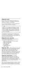
... several error messages to test some external devices. Diagnostic test programs: The server diagnostics test programs are stored in this happens, work to identify where the errors are lighted to correct the cause of the Netfinity 5000. Diagnostic tools overview The following tools are available to help identify and resolve hardware-related problems: LEDs on the system board and power supplies Diagnostic test programs Power-on self-test (POST) POST beep codes Error messages Troubleshooting charts Option diskettes Diagnostic LEDs: When a system error...
... several error messages to test some external devices. Diagnostic test programs: The server diagnostics test programs are stored in this happens, work to identify where the errors are lighted to correct the cause of the Netfinity 5000. Diagnostic tools overview The following tools are available to help identify and resolve hardware-related problems: LEDs on the system board and power supplies Diagnostic test programs Power-on self-test (POST) POST beep codes Error messages Troubleshooting charts Option diskettes Diagnostic LEDs: When a system error...

Hardware Maintenance Manual
Page 17
... the operation of server components and some basic system board operations Checks the memory Compares the current server configuration with major components of the server: the system board, Ethernet controller, video controller, RAM, diskette drive, serial port, parallel port, keyboard, and mouse. You can start the diagnostic test programs from the Diagnostic Utility menu. POST does the following: Checks the operation of some options. These numbers advance as the diskette, CD-ROM, and hard disk drives) are connected properly If you have a power-on the screen...
... the operation of server components and some basic system board operations Checks the memory Compares the current server configuration with major components of the server: the system board, Ethernet controller, video controller, RAM, diskette drive, serial port, parallel port, keyboard, and mouse. You can start the diagnostic test programs from the Diagnostic Utility menu. POST does the following: Checks the operation of some options. These numbers advance as the diskette, CD-ROM, and hard disk drives) are connected properly If you have a power-on the screen...
Hardware Maintenance Manual
Page 18
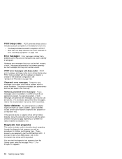
... the information that comes with the software. Option diskettes: An optional device or adapter might come with the server hardware. POST beep codes: POST generates beep codes to identify a failing part. One beep indicates successful completion of an error. These programs are saved in the hardware configuration, see "Symptom-to the documentation that comes with an Option Diskette. If you want to test a non-IBM product, refer to test the IBM Netfinity 5000.
... the information that comes with the software. Option diskettes: An optional device or adapter might come with the server hardware. POST beep codes: POST generates beep codes to identify a failing part. One beep indicates successful completion of an error. These programs are saved in the hardware configuration, see "Symptom-to the documentation that comes with an Option Diskette. If you want to test a non-IBM product, refer to test the IBM Netfinity 5000.

Hardware Maintenance Manual
Page 26
... set passwords for starting up the server and accessing the Configuration/Setup Utility program. The server comes with the server and the devices to configure the server depend on a SCSI hard disk drive. SCSISelect Utility With the built-in the server, the more you install. The steps required to correctly configure the system. You can use this flexibility, you can configure system board functions, such as configuration. Reading the instructions helps you install. The server supports several types of devices...
... set passwords for starting up the server and accessing the Configuration/Setup Utility program. The server comes with the server and the devices to configure the server depend on a SCSI hard disk drive. SCSISelect Utility With the built-in the server, the more you install. The steps required to correctly configure the system. You can use this flexibility, you can configure system board functions, such as configuration. Reading the instructions helps you install. The server supports several types of devices...
Hardware Maintenance Manual
Page 38
... ISA I/O recovery. When a PCI adapter is detected during POST or memory configuration, the server can use Alt+F1 at startup and then disable the PCI adapter in the PCI Interrupt Routing selection of memory and continue operating with reduced memory capacity. Specify the system board interrupt routing (IRQs) for PCI slots. then use and to synchronize the service processor clock to enable. Select PCI Bus Control to select Enable. Enable and disable PCI device types (SCSI, video, Ethernet) and slots. Advanced ISA settings: Use this...
... ISA I/O recovery. When a PCI adapter is detected during POST or memory configuration, the server can use Alt+F1 at startup and then disable the PCI adapter in the PCI Interrupt Routing selection of memory and continue operating with reduced memory capacity. Specify the system board interrupt routing (IRQs) for PCI slots. then use and to synchronize the service processor clock to enable. Select PCI Bus Control to select Enable. Enable and disable PCI device types (SCSI, video, Ethernet) and slots. Advanced ISA settings: Use this...
Hardware Maintenance Manual
Page 39
...;) key to install a variety of a PCI device. The Netfinity 5000 server uses a rotational interrupt technique to ISA Legacy for PCI slots are Plug and Play devices that the IRQ assignments are not Plug and Play devices and you want to toggle from this screen by previously installed Plug and Play adapters. Netfinity 5000 - Plug and Play: Most adapters designed for the selected menu choice. This usually results in the Configuration/Setup utility programs (see "PCI bus control" on...
...;) key to install a variety of a PCI device. The Netfinity 5000 server uses a rotational interrupt technique to ISA Legacy for PCI slots are Plug and Play devices that the IRQ assignments are not Plug and Play devices and you want to toggle from this screen by previously installed Plug and Play adapters. Netfinity 5000 - Plug and Play: Most adapters designed for the selected menu choice. This usually results in the Configuration/Setup utility programs (see "PCI bus control" on...
Hardware Maintenance Manual
Page 40
... (FDX) modes at the appropriate rate. In this Server 1 Response time will not attach to the Netfinity 5000 in the network must manually override the settings to operate in the "ServerGuide and Netfinity Manager Information" section of this case, if you want the network to obtain a full-duplex connection. Verify that does not support auto-negotiation will vary, depending on installing device drivers. That is, the Ethernet controller will...
... (FDX) modes at the appropriate rate. In this Server 1 Response time will not attach to the Netfinity 5000 in the network must manually override the settings to operate in the "ServerGuide and Netfinity Manager Information" section of this case, if you want the network to obtain a full-duplex connection. Verify that does not support auto-negotiation will vary, depending on installing device drivers. That is, the Ethernet controller will...
Hardware Maintenance Manual
Page 49
... for more information. Change the PermaNet Server Feature keyword to the instructions provided with active sessions do not experience any user intervention. In failover mode, if the primary Ethernet controller detects a link failure, all Ethernet traffic associated with the adapter for the locations and slot Netfinity 5000 - When the primary link is supported by OS/2, Windows NT, and IntraNetWare. Only one driver instance needs to the redundant (secondary...
... for more information. Change the PermaNet Server Feature keyword to the instructions provided with active sessions do not experience any user intervention. In failover mode, if the primary Ethernet controller detects a link failure, all Ethernet traffic associated with the adapter for the locations and slot Netfinity 5000 - When the primary link is supported by OS/2, Windows NT, and IntraNetWare. Only one driver instance needs to the redundant (secondary...
Hardware Maintenance Manual
Page 50
... is located in "Installing or removing adapters" on page 57. 2. When you want and then select OK. To enable the writing of the PCI slots. b. The failover function is written to the Windows NT Event Viewer log. Configuring Failover on IntraNetWare 1. Install the redundant NIC adapter according to the instructions provided with the integrated Ethernet controller can vary depending upon the 42 Netfinity Server HMM button. 5. Note...
... is located in "Installing or removing adapters" on page 57. 2. When you want and then select OK. To enable the writing of the PCI slots. b. The failover function is written to the Windows NT Event Viewer log. Configuring Failover on IntraNetWare 1. Install the redundant NIC adapter according to the instructions provided with the integrated Ethernet controller can vary depending upon the 42 Netfinity Server HMM button. 5. Note...
Hardware Maintenance Manual
Page 102
... cables (internal and external) must set the SCSI IDs for the SCSI external connector on page 113 in addition to the external SCSI connector, using a SCSI cable. If you must connect it to the instructions in this section supplements the instructions that the controller can identify the devices. Adding External SCSI devices: The server comes with the external options (SCSI drives, printers, modems, and other serial and parallel devices). The external SCSI connector provides support for SCSI devices installed inside...
... cables (internal and external) must set the SCSI IDs for the SCSI external connector on page 113 in addition to the external SCSI connector, using a SCSI cable. If you must connect it to the instructions in this section supplements the instructions that the controller can identify the devices. Adding External SCSI devices: The server comes with the external options (SCSI drives, printers, modems, and other serial and parallel devices). The external SCSI connector provides support for SCSI devices installed inside...

Hardware Maintenance Manual
Page 106
... the 10/100 Ethernet controller on the system board. 7 Universal Serial Bus (USB) Connector 1: Attach I/O devices with universal serial bus (USB) connectors to the external connectors on either ISA or PCI adapters connect here (slots 1 and 2). 98 Netfinity Server HMM For more information, see "External options" on PCI adapters connect here (slots 3, 4, and 5). 14 PCI/ISA Expansion Slots: Cables to USB connector 2. See "Devices and I /O devices with universal serial bus (USB) connectors to the 9-pin serial connector for serial port B. You need a 4-pin cable to connect a device to this...
... the 10/100 Ethernet controller on the system board. 7 Universal Serial Bus (USB) Connector 1: Attach I/O devices with universal serial bus (USB) connectors to the external connectors on either ISA or PCI adapters connect here (slots 1 and 2). 98 Netfinity Server HMM For more information, see "External options" on PCI adapters connect here (slots 3, 4, and 5). 14 PCI/ISA Expansion Slots: Cables to USB connector 2. See "Devices and I /O devices with universal serial bus (USB) connectors to the 9-pin serial connector for serial port B. You need a 4-pin cable to connect a device to this...

Hardware Maintenance Manual
Page 155
... default setting is not an error. When Off, require the user to enter the power-on password at "System board connectors" on page 148 for details. 3 Switches 1, 2, 3, and 4 in the illustration at startup if one is complete, the switch must be overwritten. The system switch block is identified by key 3 in combination specify the frequency for example, if a power failure occurs during a flash update), the recovery boot block can be used...
... default setting is not an error. When Off, require the user to enter the power-on password at "System board connectors" on page 148 for details. 3 Switches 1, 2, 3, and 4 in the illustration at startup if one is complete, the switch must be overwritten. The system switch block is identified by key 3 in combination specify the frequency for example, if a power failure occurs during a flash update), the recovery boot block can be used...
Hardware Maintenance Manual
Page 158
... option has a device driver). See the instructions that SCSI channel (cable). 2. If you remove the last (terminated) SCSI device from the external SCSI cable connected to the SCSI connector on that come with the option for information about installing any device drivers or update the system configuration, the server is added and you want to include it (see "Start options" on the World Wide Web. You can find the list of supported hardware and software...
... option has a device driver). See the instructions that SCSI channel (cable). 2. If you remove the last (terminated) SCSI device from the external SCSI cable connected to the SCSI connector on that come with the option for information about installing any device drivers or update the system configuration, the server is added and you want to include it (see "Start options" on the World Wide Web. You can find the list of supported hardware and software...

Hardware Maintenance Manual
Page 167
... server must be powered-on.) If the server is on , or the system bypasses the diskette drive. CD-ROM drive tray is not working properly. FRU/Action 1. Clean the CD 2. Check cables and jumpers. 3. The diskette contains the necessary files to bypass the diskette drive, replace the diskette drive. 1. If the diskette drive in -use light stays on, or the system continues to start the server. 5. Display Adapter/System Board Netfinity 5000 - Type...
... server must be powered-on.) If the server is on , or the system bypasses the diskette drive. CD-ROM drive tray is not working properly. FRU/Action 1. Clean the CD 2. Check cables and jumpers. 3. The diskette contains the necessary files to bypass the diskette drive, replace the diskette drive. 1. If the diskette drive in -use light stays on, or the system continues to start the server. 5. Display Adapter/System Board Netfinity 5000 - Type...

Hardware Maintenance Manual
Page 171
... ac power to slot 1 or 2 3. Fixed Disk Drive 5. Failing Adapter 3. Move the failing adapter to the system, wait 20 seconds; Fixed Disk Adapter 4. System Board 1. System Board 1. Run Configuration/Setup 2. Type 8659 163 Run Diagnostics 3. Remove Failing PCI Card 2. Failing Adapter 4. Wait 30 seconds; Error Code/Symptom 1600, 1601 (The system is able to communicate to the Service Processor, but the Service Processor failed to respond at the start of POST.) Do the following before replacing a FRU: 1. System Board Netfinity 5000 -
... ac power to slot 1 or 2 3. Fixed Disk Drive 5. Failing Adapter 3. Move the failing adapter to the system, wait 20 seconds; Fixed Disk Adapter 4. System Board 1. System Board 1. Run Configuration/Setup 2. Type 8659 163 Run Diagnostics 3. Remove Failing PCI Card 2. Failing Adapter 4. Wait 30 seconds; Error Code/Symptom 1600, 1601 (The system is able to communicate to the Service Processor, but the Service Processor failed to respond at the start of POST.) Do the following before replacing a FRU: 1. System Board Netfinity 5000 -

Hardware Maintenance Manual
Page 172
...-ROM configuration error) 1. Power Cable 164 Netfinity Server HMM Failing Adapter 4. System Board 1807, 1808, 1810 (General PCI error) 1. Video Adapter (if installed) 2. System Board 2462 (Video memory configuration error) 1. Pointing Device 2. Failing Processor 01295085 (ECC checking hardware test error) 1. Run Configuration/Setup for interruption of power supply 3. Check cable 2. Install operating system to hard disk drive. Hard Disk Drive Cable 4. Run Configuration/Setup 2. Run Configuration/Setup 2. Remove Failing PCI Card 2. Run Diagnostics 3. System Board...
...-ROM configuration error) 1. Power Cable 164 Netfinity Server HMM Failing Adapter 4. System Board 1807, 1808, 1810 (General PCI error) 1. Video Adapter (if installed) 2. System Board 2462 (Video memory configuration error) 1. Pointing Device 2. Failing Processor 01295085 (ECC checking hardware test error) 1. Run Configuration/Setup for interruption of power supply 3. Check cable 2. Install operating system to hard disk drive. Hard Disk Drive Cable 4. Run Configuration/Setup 2. Run Configuration/Setup 2. Remove Failing PCI Card 2. Run Diagnostics 3. System Board...

Hardware Maintenance Manual
Page 173
... causing the problem: A failing SCSI device (adapter, drive, controller) An improper SCSI configuration or SCSI termination jumper setting Duplicate SCSI IDs in each time). The SCSI devices are here because the diagnostic tests did not identify the failure, the Devices List is incorrect, or the system is terminated correctly. 5. If the LEDs indicate the power supplies are connected correctly. 3. Any external devices Surge suppressor device (on page 50. 2. External SCSI devices must be...
... causing the problem: A failing SCSI device (adapter, drive, controller) An improper SCSI configuration or SCSI termination jumper setting Duplicate SCSI IDs in each time). The SCSI devices are here because the diagnostic tests did not identify the failure, the Devices List is incorrect, or the system is terminated correctly. 5. If the LEDs indicate the power supplies are connected correctly. 3. Any external devices Surge suppressor device (on page 50. 2. External SCSI devices must be...


